EP2157536A2 - Système de surveillance, commande et saisie de données de processus techniques - Google Patents
Système de surveillance, commande et saisie de données de processus techniques Download PDFInfo
- Publication number
- EP2157536A2 EP2157536A2 EP09010313A EP09010313A EP2157536A2 EP 2157536 A2 EP2157536 A2 EP 2157536A2 EP 09010313 A EP09010313 A EP 09010313A EP 09010313 A EP09010313 A EP 09010313A EP 2157536 A2 EP2157536 A2 EP 2157536A2
- Authority
- EP
- European Patent Office
- Prior art keywords
- data
- database
- external
- format
- units
- Prior art date
- Legal status (The legal status is an assumption and is not a legal conclusion. Google has not performed a legal analysis and makes no representation as to the accuracy of the status listed.)
- Ceased
Links
Images







Classifications
-
- G—PHYSICS
- G06—COMPUTING OR CALCULATING; COUNTING
- G06Q—INFORMATION AND COMMUNICATION TECHNOLOGY [ICT] SPECIALLY ADAPTED FOR ADMINISTRATIVE, COMMERCIAL, FINANCIAL, MANAGERIAL OR SUPERVISORY PURPOSES; SYSTEMS OR METHODS SPECIALLY ADAPTED FOR ADMINISTRATIVE, COMMERCIAL, FINANCIAL, MANAGERIAL OR SUPERVISORY PURPOSES, NOT OTHERWISE PROVIDED FOR
- G06Q10/00—Administration; Management
- G06Q10/06—Resources, workflows, human or project management; Enterprise or organisation planning; Enterprise or organisation modelling
Definitions
- the present invention relates to a system for monitoring, control and data acquisition of technical processes, with at least one communication unit as an interface for bidirectional data exchange with external units.
- the present invention equally relates to a method for monitoring, control and data acquisition of technical processes by means of bidirectional data exchange with external units.
- SCADA Supervisory Control and Data Acquisition
- a SCADA system of the type mentioned above is used to monitor the installation of process-related controls and to visualize process data.
- RTU Remote Terminal Unit
- PLC programmable logic controller
- process-related automation serve to optimize the function of process-related automation, in particular to specify or receive manipulated variables and setpoints.
- the data received from the process-related devices for example status information such as, for example, switch positions, are received and then presented in a user-friendly display. This allows the user to intervene in the process in a controlling manner.
- the systems typically implement a database that includes data points.
- a data point contains an input or output value that is monitored and controlled by the system.
- Most data points in the prior art are traded as a combination of timestamped values. A series of data points then allows the historical evaluation.
- a disadvantage of the known systems is that a comprehensive monitoring of the technical process involving all relevant data and a uniform system is usually not possible.
- many data characterizing the process are in commercial databases, for example, SAP.
- data about sold-off quantities of a product can be stored.
- an evaluation of the sold-off product quantities also makes it possible to make a statement about, for example, the level of a container storing this product in the process.
- technical data such as bills of material, order numbers, operating instructions, also conventionally usually stored in separate databases. These quantities are also important for comprehensive monitoring of a technical process.
- Object of the present invention is therefore to propose such a system and such a method.
- this object is achieved in a generic system in that at least one communication unit for communication with at least one external electronic Process database and is formed with at least one communication unit for communication with at least one external technical control units. It is therefore proposed according to the invention that a conventional SCADA system is developed in such a way that it enables data exchange both with, for example, process-oriented programmable logic controllers and with external databases, such as SAP databases, within one and the same system. It is thus achieved according to the invention advantageously a combination of automation technology and other databases.
- the communication unit for addressing each external unit is formed by means of a unique identifier, wherein identifiers for process databases on their primary key and identifiers for control units are designed to refer to a memory address.
- identifiers for process databases on their primary key and identifiers for control units are designed to refer to a memory address.
- a communication channel data base is present in which identifiers for communication with external units are stored. This makes it possible, before starting the actual control and monitoring of a technical process, to prepare the system for the PLC controls actually present in the system to be monitored and for the additional databases to be read. During the control, it is then ensured according to the invention that only actually existing memory areas in controllers and databases are addressed and read out by the system.
- a data structure database is present in which data structures are stored with the system connectable external units.
- the process data which can be read out from a controller, its format and the like can be stored in a desired level of detailing.
- specific status messages within the structure according to the invention can also be assigned to process parameters read out of a PLC.
- in an embodiment of the invention means for verifying data compatibility, in particular with respect to a data format and / or a data width, between elements of the data structure database and elements of the communication channel database intended. If the system implements a relational database, such a compatibility check may be performed, in particular via an integrity check of the unique keys of each table. It settles on this Advantageously achieve a linkage of available communication channels with the appropriate data structures.
- the system according to the invention is further improved if there is a connection database in which desired compatible pairings of elements of the data structure basis and elements of the communication channel database are stored.
- the system can then be configured in advance by preparing the monitoring, control and data acquisition in a suitable manner, so that during the actual monitoring operation, communication can only take place between suitable structures and channels.
- a linking database for storing links between process data from a process database and process data from a technical control unit for the purpose of visualizing said data.
- flow measurement data read from a PLC can be displayed concurrently with sales numbers of that product stored in an SAP database to advantageously provide an overview of production access and sales exit.
- each external unit is addressed by means of a unique identifier, wherein identifiers for process databases from their primary key and identifiers for control units are formed from a memory address.
- a particularly efficient embodiment of the method according to the invention provides that identifiers for the exchange of data with external units before the start of monitoring, control and data acquisition are stored in a communication channel database. According to the invention, it is therefore intended to carry out a preconfiguration of the monitoring system in order to link together only "suitable", ie compatible, signals in monitoring mode with the aid of the communication channel database.
- memory areas on external units are preferably addressed according to a uniform format for all external units, in particular SQL format.
- SQL format in particular also SQL-like formats can be used.
- a unified coupling to evaluation routines is made possible in this way. For example, when configuring evaluation routines, it is not necessary to consider from the outset whether they should receive values from a database or values read from a PLC as an input variable. An evaluation can thus be created and implemented modularly.
- data structures are read out from a data structure database with the system of connectable external units and before each data exchange becomes data compatibility, in particular with regard to a data format and / or a data width, between elements in the data structure database and elements a communication channel data base checked, with a data exchange is performed only between compatible elements.
- the course of the method according to the invention in this embodiment is then analogous to the processes of an electrical jumper distributor. For there are virtually made links between predetermined data structures and associated, ie compatible, communication channels.
- a communication channel can be connected either to an external database or to a process-oriented PLC.
- the method enables a comprehensive evaluation and visualization of a technical process.
- the visualization and evaluation is neither limited to pure process data read by PLC nor to purely commercial data stored in databases. Rather, according to the invention, a comprehensive evaluation of the system taking into account these two, not directly linkable data types according to the prior art.
- FIG. 1 shows a schematic overview of the general architecture of a system according to the invention for monitoring, control and data acquisition according to the invention.
- the system will hereinafter be referred to simply as a monitoring system.
- the monitoring system is generally designated by the reference numeral 1.
- the system limits are indicated in the illustration with a dashed line.
- the monitoring system 1 is connected to a programmable logic controller (PLC) 2, and an external database 3.
- PLC programmable logic controller
- SPS 2 and / or databases 3 can be included in the monitoring system 1 according to the invention.
- the monitoring system 1 is also connected via a Blackberry service 4 for mobile communication with a mobile terminal 16, wherein the mobile terminal 16 is set up as a Blackberry client.
- the PLC 2 is connected via a plant network 5 according to the Profinet standard and a TCP / IP service 6 to a communication server 7 of the monitoring system 1 according to the invention.
- the communication server 7 forms in this way the link between the monitoring system 1 according to the invention and the Automation technology, which is in communication with the PLC 2.
- the communication server 7 can be set up directly next to the automation devices of the technical system. Because the communication server 7 is according to the embodiment of the invention described here autonomous from the other components of the monitoring system 1. In particular, there is no database connection.
- the database 3 may be, for example, an SAP database or Microsoft Access database.
- the database 3 is also connected to the communication server 7 of the monitoring system 1 via a database connection 8 and an SQL server 9.
- the database connections 8, 9 are only to be understood as examples. The person skilled in the art will recognize that other possibilities of data connection to the communication server also exist within the scope of the invention.
- the monitoring system 1 comprises, as further essential components, a trend server 10 and a notification server 11. Both the trend server 10 and the notification server 11 communicate bidirectionally with an internal interface 12 of the communication server 7.
- the trend server 10 is used to manage the measured values configured in a project specifically for the trend server 10. For this purpose, the trend server 10 displays in a predetermined time interval a determined actual value, which was received via the communication server 7 from the database 3 or the PLC 2, in a project database 13. In this case, preconfigured parameters for averaging or for smoothing the measured value read out from the PLC 2 and / or database 3 can be taken into account in the actual value determination.
- the Notification Server 11 manages the digital messages specially configured for the Notification Server 11 in a dedicated project, which were received via the Communication Server from the PLC 2 and / or the database 3.
- the Notification Server is functionally designed to issue a message when certain data events occur.
- a data event in this sense can be, for example, a change in the edge of the measured value in question. Such an edge change is obtained, for example, in the notification server 11 by comparing the old value with the new value.
- the notification server 11 then recognizes a rising or falling edge of a message by a change from 0 to 1 or from 1 to 0.
- the notification server 11 of the monitoring system 1 reads the associated memory area of the PLC 2 and / or database 3 by means of the communication server 7.
- a message 14 generated by the notification server 11 is transmitted within the monitoring system 1 to a device manager service 15.
- the device manager service 15 is responsible for communication with mobile terminals, in particular a BlackBerry server 4.
- the device manager 15 thus acts as a link between the monitoring system 1 according to the invention and the Blackberry terminals 16.
- a data exchange between the device manager 15 and the Blackberry service 4 is carried out in particular via a PUSH service 17. This is done by the Notification server 11 generated messages 14 via the device manager 15 after creation directly to the BlackBerry client 16 transmitted without the Blackberry client 16 must start a request.
- the project manager service 18 essentially serves for Connection to a system database
- the project manager service 18 essentially serves for the configuration and configuration as well as for communication with the project database 13.
- the data are stored which form the project-independent framework of the monitoring system 1 according to the invention. This includes in particular all system parameters, an overview of installed modules and project databases 13, a user / terminal management and the central licensing of all elements. In addition, all accesses and requests from outside are logged in the system database 20.
- the project database 13 contains the data required for a unified bidirectional communication according to the invention with the PLC 2 as well as with the database 3.
- FIG. 2 illustrates the basic data model of a relational database with which it is ensured according to the invention that a uniform integration of external databases 3 as well as external SPS 2 into the monitoring system 1 according to the invention is possible. At the same time, an allocation of compatible data types is ensured.
- relational database is implemented in the project database 13. It comprises a channel type table 21 and a structure database 22. Links of elements in the Channel type table 21 having the structure database 22 to be admitted by the monitoring system 1 according to the invention is stored in a channel connection database 23.
- channel type table 21 serving as a link table
- the available channel types are stored as a combination of data type 24 and data format 25.
- this information is added in a further connection table, called channel database 23.
- the different database and PLC types that can be connected to the monitoring system 1 are defined in a table 101. Which method the monitoring system 1 can communicate with these external devices can be seen from the enumeration 100 and the link in Table 104.
- Table 104 the available drivers of external devices 2, 3 are managed. In order to actually set up an external device 2, 3 in the project, it is created as an element in the structure database 22 and specified via the table 106 with the driver selection 104.
- the channel resources available with respect to the type of device stored in the table 101 are independent of the driver and stored in the link table 105.
- the channel resources result from a combination between channel group according to Table 102, eg inputs, flags, table etc., and channel type according to Table 23.
- channel resources determine the addressable range available with respect to the respective external device 2, 3, resulting in the addressed channel in the table 107. This can be converted in register to the parameter from FIG. 23 in the table 108 to an addressable parameter.
- channel type table 21 available communication channels are stored together with data concerning the channel type and the channel format.
- the possible values for the channel type are related to the channel type table 21 from the channel type database 24 attached via a 1: n link.
- Possible channel formats are related to the channel type table 21 from the channel format database 25 also attached to a 1: n link.
- FIG. 2 (b) By way of example, a possible assignment of the channel type table 21 according to the invention is shown in a table. It can be seen that in the column headed "Type" the possible values are selected from the set of bit, byte, word, double word, data. It can also be seen that in the Format column, one of the values binary, bool, decimal, hexadecimal, character, floating point, cell, table is selected.
- Each of these channel types has a unique index associated with the corresponding overwritten column.
- An index uniquely describes an available, predefined channel type. It can be seen that a channel can thus equally define a communication with an external PLC 2, as well as a communication with an external database 3.
- the administration and addressing within the monitoring system 1 according to the invention is completely identical. In particular, there is no so-called media break, as is the case in the prior art.
- data structures are stored within a given project in a folder hierarchy.
- the data are hierarchically recorded and can be displayed in a visualization in a project tree.
- the state parameters that are possible and to be monitored for a specific plant section of a technical installation are stored hierarchically.
- a structure can refer both to a value read out by the PLC 2 and to a value read from the database 3.
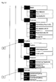
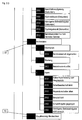
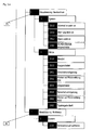
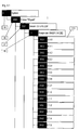
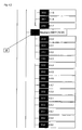
- FIG. 3.1. to 3.5 For example, a project tree 26 for a structure is shown using the example of a drive.
- the Figures 3.1. to 3.5 refer to the same project tree 26 and are arranged one above the other to interpret, the Figure 3.1 , to supreme and the Figure 3.5 , is to be arranged at the bottom.
- Out Figure 3.1 It can be seen that the structure of the drive is classified in the category "technology" 27.
- the project tree 26 contains technology data 28 for an engine_1.
- Hierarchically ordered receive the technology data 28 for the Motor_1 data via inputs 29, outputs 30 (see. Figure 3.2 .), Parameter 31, archive data 32 (cf. Figure 3.3 .), a visualization mode 33 (this is for clarity on the Figure 3.4 , repeated), operation modes 34.
- the inputs 29 of the motor_1 28 include a fault acknowledgment, a lamp test and an emergency stop OK.
- Enable values which are also defined as the input 29 of the motor 28, include commands for power-on enable, power-off enable, operation enable, delayed operation enable, protect enable, individual operation enable, message enable, and lamp enable. Further, input commands as a subset of the inputs 29 include a power-on command and a power-off command.
- a feedback from the main contactor a ready to go OK signal, a repair switch OK signal and a bimetal OK signal.
- the outputs 30 of the motor 28 within the structure 26 of the drive include values for on-delay and off-delay in seconds (see FIG. Figure 3.2 ) as well as a response time, delayed operation release time, jog release time, in seconds, as well as the operating hours until the next service.
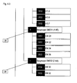
- FIGS 4.1 show by way of example a project tree 35 for linking to the PLC 2.
- the context of Figures 4.1. to 4.3 is analogous to those of Figures 3.1. to 3.5 , to interpret. The figures are thus arranged one above the other.
- the structure 35 of the project tree of the PLC 2 is assigned to the folder category 36 "physics".
- this folder parameters are stored according to this embodiment, which can be read by the PLC 2.
- technology data 37 of an exemplary PLC 2 with the designation "Simatic S7-315-2DP" are stored.
- 38 readable parameters E 0.0 ... E 1.7 or A 4.0 ... A 5.7 or EW20 ... EW 26 or AW 30 ... AW 32 are defined for four different modules.
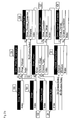
- FIG. 7 is the process of assigning a data channel to a structure according to FIG. 2 (a) and 2 B additionally illustrated graphically.
- this assignment is shown using the example of a technological parameter.
- the main contactor feedback parameter in the peripheral folder of the inputs 29 of the technology data folder 28 is displayed on the Figure 3.2 , connected to a suitable channel.
- the element BIT and from the channel format database 25 the element BOOL is selected as a combination in the channel type table 21 to designate a channel type BIT having the format BOOL.
- This channel has according to FIG. 2 (b) the index 2 within the channel type table 21.
- This channel 2 of the channel type table 21 is now linked in the channel connection table 23 with the parameter "main contactor feedback" of the corresponding structure element of the corresponding structure database 22.
- This means that a message "main contactor feedback" read from an external data system in the Bool format is assigned the corresponding data channel from the channel type table 21.
- a proper assignment and evaluation of the parameter "feedback main contactor" in the monitoring system 1 of the invention is thus ensured.
- FIG. 7b shown as an example within the channel connection table 23, a parameter EW 20 of the module SM331 according to the structure 35 of the Figures 4.1. to 4.3 a word-type channel in decimal format.
- the channel is a word that should be displayed as a decimal number.
- SQL-like languages can also be used.
- Cell stands for the name of the parameter, Format_ID for the combination of type and format, which is the unique one Relationsindex returns Page for the range, group, or table in which the parameter lies, as well as Rule for the rule of how to uniquely address the parameter on the Page.
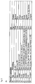
- FIG. 5 Finally, a table is given, which provides information about which types of parameters and formats can be connected to the system and method according to the invention with external devices, according to a preferred embodiment.
- connection parameters on the part of the monitoring system 1 according to the invention relate in the table to the first three columns, that is to say the columns 'data type', 'data format', 'representation'.
- the right two columns, columns 4 and 5, concern the type and format of the respective external device.
- the external device is the PLC 2.
- the index column the unique channel number according to the channel definition table 21 is indicated.
- the data type in column 3, the representation within the monitoring system 1.
- Columns 4 and 5 describe the type and format of the linked PLC parameters.
- FIG. 5 (b) shows the table analogously FIG. 5 (a)
- Deviating from the FIG. 5 (a) shows the table in FIG. 5 (b) the definition in the translation of formats of the monitoring system according to the invention with the database 3.
- Data exchange with the external databases and PLC is bidirectional.
- the system is capable of bidirectional communication with Blackberry mobile clients through the Blackberry service.
- Blackberry client can access both data from external databases as well as the parameters that are read from external PLCs.
Landscapes
- Engineering & Computer Science (AREA)
- Business, Economics & Management (AREA)
- Human Resources & Organizations (AREA)
- Strategic Management (AREA)
- Economics (AREA)
- Entrepreneurship & Innovation (AREA)
- Educational Administration (AREA)
- Game Theory and Decision Science (AREA)
- Development Economics (AREA)
- Marketing (AREA)
- Operations Research (AREA)
- Quality & Reliability (AREA)
- Tourism & Hospitality (AREA)
- Physics & Mathematics (AREA)
- General Business, Economics & Management (AREA)
- General Physics & Mathematics (AREA)
- Theoretical Computer Science (AREA)
- Programmable Controllers (AREA)
- Selective Calling Equipment (AREA)
Applications Claiming Priority (1)
| Application Number | Priority Date | Filing Date | Title |
|---|---|---|---|
| DE102008038968A DE102008038968A1 (de) | 2008-08-13 | 2008-08-13 | System zur Überwachung, Steuerung und Datenerfassung technischer Prozesse |
Publications (2)
| Publication Number | Publication Date |
|---|---|
| EP2157536A2 true EP2157536A2 (fr) | 2010-02-24 |
| EP2157536A3 EP2157536A3 (fr) | 2010-08-11 |
Family
ID=41259699
Family Applications (1)
| Application Number | Title | Priority Date | Filing Date |
|---|---|---|---|
| EP09010313A Ceased EP2157536A3 (fr) | 2008-08-13 | 2009-08-11 | Système de surveillance, commande et saisie de données de processus techniques |
Country Status (3)
| Country | Link |
|---|---|
| US (1) | US20100039952A1 (fr) |
| EP (1) | EP2157536A3 (fr) |
| DE (1) | DE102008038968A1 (fr) |
Cited By (2)
| Publication number | Priority date | Publication date | Assignee | Title |
|---|---|---|---|---|
| EP2557464A1 (fr) * | 2011-08-12 | 2013-02-13 | Siemens Aktiengesellschaft | Procédé destiné au fonctionnement d'un système d'automatisation |
| DE102012200066A1 (de) * | 2012-01-03 | 2013-07-04 | Endress + Hauser Process Solutions Ag | Verfahren und Einrichtung zur Visualisierung von Informationen in einer Prozessanlage |
Families Citing this family (7)
| Publication number | Priority date | Publication date | Assignee | Title |
|---|---|---|---|---|
| GB2471483A (en) * | 2009-06-30 | 2011-01-05 | Nokia Corp | Data type selection based on channel type |
| DE102011000823A1 (de) * | 2011-02-18 | 2012-08-23 | Dewind Europe Gmbh | Wartungsdatenspeicherung von Energieumwandlungsanlagen |
| DE102011056171A1 (de) | 2011-12-08 | 2013-06-13 | Schad Gmbh | Steuerungsvorrichtung für Maschinenanlagen |
| JP6395830B2 (ja) * | 2013-11-12 | 2018-09-26 | アルファ・アセンブリー・ソリューションズ・インコーポレイテッドAlpha Assembly Solutions Inc. | フラックス配合物 |
| DE102019216406B4 (de) * | 2019-10-24 | 2023-07-20 | Robert Bosch Gmbh | Kommunikationssystem zum Überwachen von Prozesseinheiten |
| EP3862824B1 (fr) * | 2020-02-04 | 2023-01-11 | Siemens Aktiengesellschaft | Module d'interface pour la configuration et le paramétrage d'un participant de bus de terrain |
| WO2021166310A1 (fr) * | 2020-02-20 | 2021-08-26 | 株式会社島津製作所 | Dispositif d'évaluation de photoréaction et procédé de calcul du compte de photons |
Citations (1)
| Publication number | Priority date | Publication date | Assignee | Title |
|---|---|---|---|---|
| DE10223725A1 (de) * | 2001-09-17 | 2003-04-03 | Fisher Rosemount Systems Inc | Verschmelzung von Prozeßleistungsüberwachung mit Prozeßausrüstungsüberwachung und -steuerung |
Family Cites Families (28)
| Publication number | Priority date | Publication date | Assignee | Title |
|---|---|---|---|---|
| GB2263989B (en) * | 1992-02-01 | 1995-05-31 | Motorola Israel Ltd | Supervisory control and data acquisition system |
| US5568402A (en) * | 1994-04-11 | 1996-10-22 | Gse Process Solutions, Inc. | Communication server for communicating with a remote device |
| US6122514A (en) * | 1997-01-03 | 2000-09-19 | Cellport Systems, Inc. | Communications channel selection |
| US6157630A (en) * | 1998-01-26 | 2000-12-05 | Motorola, Inc. | Communications system with radio device and server |
| US6148244A (en) * | 1998-04-13 | 2000-11-14 | Intellution, Inc. | Equipment pathing and unit allocation for a process control system |
| US6289339B1 (en) * | 1999-02-19 | 2001-09-11 | Nortel Networks Limited | Method and apparatus for filtering a notification message from a database |
| US6700590B1 (en) * | 1999-11-01 | 2004-03-02 | Indx Software Corporation | System and method for retrieving and presenting data using class-based component and view model |
| US20020029097A1 (en) * | 2000-04-07 | 2002-03-07 | Pionzio Dino J. | Wind farm control system |
| US20020022969A1 (en) * | 2000-07-07 | 2002-02-21 | Berg Marc Van Den | Remote automated customer support for manufacturing equipment |
| US6643555B1 (en) * | 2000-10-10 | 2003-11-04 | Schneider Automation Inc. | Method and apparatus for generating an application for an automation control system |
| US6950851B2 (en) * | 2001-04-05 | 2005-09-27 | Osburn Iii Douglas C | System and method for communication for a supervisory control and data acquisition (SCADA) system |
| US7035877B2 (en) * | 2001-12-28 | 2006-04-25 | Kimberly-Clark Worldwide, Inc. | Quality management and intelligent manufacturing with labels and smart tags in event-based product manufacturing |
| US20030149608A1 (en) * | 2002-02-06 | 2003-08-07 | Kall Jonathan J. | Suite of configurable supply chain infrastructure modules for deploying collaborative e-manufacturing solutions |
| DE10223428A1 (de) * | 2002-05-25 | 2004-01-08 | Abb Patent Gmbh | System und Verfahren zur ereignis- und bedarfsgesteuerten Überwachung und Steuerung technischer Anlagen |
| DE10235794A1 (de) * | 2002-08-05 | 2004-03-04 | Siemens Ag | System und Verfahren zur zustandsorientierten Instandhaltung |
| GB0228807D0 (en) * | 2002-12-11 | 2003-01-15 | Koninkl Philips Electronics Nv | Opportunistic location tracking |
| US7895191B2 (en) * | 2003-04-09 | 2011-02-22 | International Business Machines Corporation | Improving performance of database queries |
| US7685127B2 (en) * | 2003-06-04 | 2010-03-23 | Sap Ag | Database access system, method of accessing a database, and method of designing a database access system |
| US6799080B1 (en) * | 2003-06-12 | 2004-09-28 | The Boc Group, Inc. | Configurable PLC and SCADA-based control system |
| DE10343251A1 (de) * | 2003-09-17 | 2005-05-12 | Siemens Ag | HMI System mit einem mobilen Bedien- und Beobachtungsgerät für sicherheitsrelevante Bedienungen an einer technischen Anlage |
| US7392104B1 (en) * | 2003-09-24 | 2008-06-24 | Rockwell Automation Technologies, Inc. | Material reservation distribution system and method |
| US7013203B2 (en) * | 2003-10-22 | 2006-03-14 | General Electric Company | Wind turbine system control |
| US7840607B2 (en) * | 2004-08-06 | 2010-11-23 | Siemens Aktiengesellschaft | Data mart generation and use in association with an operations intelligence platform |
| US7840594B2 (en) * | 2005-01-24 | 2010-11-23 | Indusoft, Inc. | Method and system for communicating between an embedded device and relational databases |
| US20060218116A1 (en) * | 2005-03-28 | 2006-09-28 | O'hearn James E | Pass-through interface queries to populate a class-based model |
| US20070233655A1 (en) * | 2006-04-03 | 2007-10-04 | National Instruments Corporation | Graphical program representation of queries |
| DE102007026176A1 (de) * | 2007-01-04 | 2008-07-17 | Dewind Ltd. | SCADA-Einheit |
| US7890357B2 (en) * | 2007-11-20 | 2011-02-15 | Hartford Fire Insurance Company | System and method for identifying and evaluating nanomaterial-related risk |
-
2008
- 2008-08-13 DE DE102008038968A patent/DE102008038968A1/de not_active Withdrawn
-
2009
- 2009-08-11 EP EP09010313A patent/EP2157536A3/fr not_active Ceased
- 2009-08-13 US US12/540,535 patent/US20100039952A1/en not_active Abandoned
Patent Citations (1)
| Publication number | Priority date | Publication date | Assignee | Title |
|---|---|---|---|---|
| DE10223725A1 (de) * | 2001-09-17 | 2003-04-03 | Fisher Rosemount Systems Inc | Verschmelzung von Prozeßleistungsüberwachung mit Prozeßausrüstungsüberwachung und -steuerung |
Non-Patent Citations (2)
| Title |
|---|
| "Analyse, Design und Realisierung eines webbasierten SCADA Systems mit OPC XML-DA Schnittstelle zu mehreren Soft-SPS Systemen", 20050901, 1 September 2005 (2005-09-01), pages 1 - 53, XP007918362, Retrieved from the Internet <URL:http://astro.uni-wuppertal.de/html/Theses/Barkhausen-diplom.pdf> * |
| "Data Access Custom Interface Standard", OPC DATA ACCESS CUSTOM INTERFACE SPECIFICATION 2.04,, no. Version 2.05A, 28 June 2002 (2002-06-28), pages 1 - 194, XP007918359, Retrieved from the Internet <URL:http://read.pudn.com/downloads137/doc/585853/OPCDASpecification.pdf> * |
Cited By (4)
| Publication number | Priority date | Publication date | Assignee | Title |
|---|---|---|---|---|
| EP2557464A1 (fr) * | 2011-08-12 | 2013-02-13 | Siemens Aktiengesellschaft | Procédé destiné au fonctionnement d'un système d'automatisation |
| US9563181B2 (en) | 2011-08-12 | 2017-02-07 | Siemens Aktiengesellschaft | Method for operating an automation system |
| DE102012200066A1 (de) * | 2012-01-03 | 2013-07-04 | Endress + Hauser Process Solutions Ag | Verfahren und Einrichtung zur Visualisierung von Informationen in einer Prozessanlage |
| DE102012200066B4 (de) * | 2012-01-03 | 2020-09-03 | Endress + Hauser Process Solutions Ag | Verfahren und Einrichtung zur Visualisierung von Informationen in einer Prozessanlage |
Also Published As
| Publication number | Publication date |
|---|---|
| US20100039952A1 (en) | 2010-02-18 |
| DE102008038968A1 (de) | 2010-02-18 |
| EP2157536A3 (fr) | 2010-08-11 |
Similar Documents
| Publication | Publication Date | Title |
|---|---|---|
| EP2157536A2 (fr) | Système de surveillance, commande et saisie de données de processus techniques | |
| EP1096348B1 (fr) | Intégration d'un appareil de commande sur site dans un système de commande d'une installation | |
| DE102009045386A1 (de) | Verfahren zum Betreiben eines Feldbus-Interface | |
| DE102007026678A1 (de) | Verfahren zum Austausch eines defekten Feldgerätes gegen ein neues Feldgerät in einem über digitalen Feldbus kommunizierenden System, insbesondere Automatisierungssystem | |
| DE112004000223T5 (de) | Schnittstellenmodul zur Verwendung mit einem Modbus-Gerätenetz und Fieldbus-Gerätenetz | |
| DE102019107401A1 (de) | Systeme und verfahren zur verwaltung von warnungen im zusammenhang mit geräten eines prozesssteuerungssystems | |
| WO2013139569A1 (fr) | Procédé de paramétrage d'un appareil de terrain | |
| EP3699704B1 (fr) | Système et procédé de vérification des exigences du système des systèmes cyber-physiques | |
| DE102010063164A1 (de) | Verfahren zum Integrieren von mindestens einem Feldgerät in ein Netzwerk der Automatisierungstechnik | |
| DE19614748C2 (de) | Fehlerdiagnose-Verfahren | |
| EP3637205A1 (fr) | Déclenchement de l'image sur une station client de l'opérateur | |
| EP2520991A1 (fr) | Procédé d'accès commandé au comportement d'un sous-module | |
| DE102008038501A1 (de) | Verfahren zum Bestimmen einer statischen Datenstruktur eines Feldgerätes | |
| DE10208530A1 (de) | Betriebseinheit, Peripheriegerät und Verfahren zum Betrieb eines Peripheriegeräts | |
| EP2713301A1 (fr) | Procédé et système de liaison d'une commande pour une machine sur un système informatique placé en amont | |
| DE4413836A1 (de) | System zum Anschluß von nicht netzwerkfähigen technischen Maschinen an ein komplexes Netzwerk | |
| DE10131944A1 (de) | Verfahren zur Verarbeitung von Daten | |
| EP4213469A1 (fr) | Procédé d'établissement de communication réseau en utilisant opc ua | |
| EP1814002A1 (fr) | Saisie de données dans un système d'automatisation distribué | |
| EP4176579B1 (fr) | Procédé de fonctionnement d'un système d'automatisation d'une machine ou d'une installation | |
| EP3652595B1 (fr) | Procédé et système pour surveiller une installation de la technologie d'automatisation | |
| DE102016119744A1 (de) | Verfahren und System zum Verhindern eines unerwünschten Zugriffs auf ein Feldgerät | |
| EP1454201B1 (fr) | Systeme d'ingenierie et systeme d'automatisation | |
| DE102016122051A1 (de) | Verfahren und System zum Ermitteln von Diagnoseinformationen von zumindest einem Feldgerät der Prozessautomatisierung | |
| DE102010027963A1 (de) | Verfahren zum Betreiben eines Feldgerätes der Prozessautomatisierungstechnik |
Legal Events
| Date | Code | Title | Description |
|---|---|---|---|
| PUAI | Public reference made under article 153(3) epc to a published international application that has entered the european phase |
Free format text: ORIGINAL CODE: 0009012 |
|
| AK | Designated contracting states |
Kind code of ref document: A2 Designated state(s): AT BE BG CH CY CZ DE DK EE ES FI FR GB GR HR HU IE IS IT LI LT LU LV MC MK MT NL NO PL PT RO SE SI SK SM TR |
|
| AX | Request for extension of the european patent |
Extension state: AL BA RS |
|
| PUAL | Search report despatched |
Free format text: ORIGINAL CODE: 0009013 |
|
| AK | Designated contracting states |
Kind code of ref document: A3 Designated state(s): AT BE BG CH CY CZ DE DK EE ES FI FR GB GR HR HU IE IS IT LI LT LU LV MC MK MT NL NO PL PT RO SE SI SK SM TR |
|
| AX | Request for extension of the european patent |
Extension state: AL BA RS |
|
| RIC1 | Information provided on ipc code assigned before grant |
Ipc: G05B 19/05 20060101ALI20100708BHEP Ipc: G06Q 10/00 20060101AFI20091116BHEP |
|
| 17P | Request for examination filed |
Effective date: 20110211 |
|
| 17Q | First examination report despatched |
Effective date: 20110503 |
|
| RAP1 | Party data changed (applicant data changed or rights of an application transferred) |
Owner name: SCHAD GMBH |
|
| STAA | Information on the status of an ep patent application or granted ep patent |
Free format text: STATUS: THE APPLICATION HAS BEEN REFUSED |
|
| 18R | Application refused |
Effective date: 20130314 |