EP2157665A1 - UWB-Antenne und Detektionsvorrichtung für Transportmittel - Google Patents
UWB-Antenne und Detektionsvorrichtung für Transportmittel Download PDFInfo
- Publication number
- EP2157665A1 EP2157665A1 EP20090158876 EP09158876A EP2157665A1 EP 2157665 A1 EP2157665 A1 EP 2157665A1 EP 20090158876 EP20090158876 EP 20090158876 EP 09158876 A EP09158876 A EP 09158876A EP 2157665 A1 EP2157665 A1 EP 2157665A1
- Authority
- EP
- European Patent Office
- Prior art keywords
- uwb
- uwb antenna
- antenna
- horizontal
- dielectric substrate
- Prior art date
- Legal status (The legal status is an assumption and is not a legal conclusion. Google has not performed a legal analysis and makes no representation as to the accuracy of the status listed.)
- Ceased
Links
- 238000001514 detection method Methods 0.000 title description 2
- 239000000758 substrate Substances 0.000 claims abstract description 21
- 238000000034 method Methods 0.000 claims description 5
- 238000012544 monitoring process Methods 0.000 description 3
- 238000007796 conventional method Methods 0.000 description 2
- 238000013461 design Methods 0.000 description 2
- 238000005259 measurement Methods 0.000 description 2
- 208000010125 myocardial infarction Diseases 0.000 description 2
- 230000005855 radiation Effects 0.000 description 2
- 206010039203 Road traffic accident Diseases 0.000 description 1
- 230000001066 destructive effect Effects 0.000 description 1
- 238000004519 manufacturing process Methods 0.000 description 1
- 210000000056 organ Anatomy 0.000 description 1
- 238000011160 research Methods 0.000 description 1
- 230000000241 respiratory effect Effects 0.000 description 1
Images




Classifications
-
- H—ELECTRICITY
- H01—ELECTRIC ELEMENTS
- H01Q—ANTENNAS, i.e. RADIO AERIALS
- H01Q1/00—Details of, or arrangements associated with, antennas
- H01Q1/27—Adaptation for use in or on movable bodies
- H01Q1/32—Adaptation for use in or on road or rail vehicles
- H01Q1/325—Adaptation for use in or on road or rail vehicles characterised by the location of the antenna on the vehicle
- H01Q1/3291—Adaptation for use in or on road or rail vehicles characterised by the location of the antenna on the vehicle mounted in or on other locations inside the vehicle or vehicle body
-
- A—HUMAN NECESSITIES
- A61—MEDICAL OR VETERINARY SCIENCE; HYGIENE
- A61B—DIAGNOSIS; SURGERY; IDENTIFICATION
- A61B5/00—Measuring for diagnostic purposes; Identification of persons
- A61B5/02—Detecting, measuring or recording for evaluating the cardiovascular system, e.g. pulse, heart rate, blood pressure or blood flow
- A61B5/0205—Simultaneously evaluating both cardiovascular conditions and different types of body conditions, e.g. heart and respiratory condition
-
- A—HUMAN NECESSITIES
- A61—MEDICAL OR VETERINARY SCIENCE; HYGIENE
- A61B—DIAGNOSIS; SURGERY; IDENTIFICATION
- A61B5/00—Measuring for diagnostic purposes; Identification of persons
- A61B5/05—Detecting, measuring or recording for diagnosis by means of electric currents or magnetic fields; Measuring using microwaves or radio waves
- A61B5/0507—Detecting, measuring or recording for diagnosis by means of electric currents or magnetic fields; Measuring using microwaves or radio waves using microwaves or terahertz waves
-
- A—HUMAN NECESSITIES
- A61—MEDICAL OR VETERINARY SCIENCE; HYGIENE
- A61B—DIAGNOSIS; SURGERY; IDENTIFICATION
- A61B5/00—Measuring for diagnostic purposes; Identification of persons
- A61B5/68—Arrangements of detecting, measuring or recording means, e.g. sensors, in relation to patient
- A61B5/6887—Arrangements of detecting, measuring or recording means, e.g. sensors, in relation to patient mounted on external non-worn devices, e.g. non-medical devices
- A61B5/6893—Cars
-
- G—PHYSICS
- G01—MEASURING; TESTING
- G01S—RADIO DIRECTION-FINDING; RADIO NAVIGATION; DETERMINING DISTANCE OR VELOCITY BY USE OF RADIO WAVES; LOCATING OR PRESENCE-DETECTING BY USE OF THE REFLECTION OR RERADIATION OF RADIO WAVES; ANALOGOUS ARRANGEMENTS USING OTHER WAVES
- G01S13/00—Systems using the reflection or reradiation of radio waves, e.g. radar systems; Analogous systems using reflection or reradiation of waves whose nature or wavelength is irrelevant or unspecified
- G01S13/02—Systems using reflection of radio waves, e.g. primary radar systems; Analogous systems
- G01S13/0209—Systems with very large relative bandwidth, i.e. larger than 10 %, e.g. baseband, pulse, carrier-free, ultrawideband
-
- G—PHYSICS
- G01—MEASURING; TESTING
- G01S—RADIO DIRECTION-FINDING; RADIO NAVIGATION; DETERMINING DISTANCE OR VELOCITY BY USE OF RADIO WAVES; LOCATING OR PRESENCE-DETECTING BY USE OF THE REFLECTION OR RERADIATION OF RADIO WAVES; ANALOGOUS ARRANGEMENTS USING OTHER WAVES
- G01S13/00—Systems using the reflection or reradiation of radio waves, e.g. radar systems; Analogous systems using reflection or reradiation of waves whose nature or wavelength is irrelevant or unspecified
- G01S13/88—Radar or analogous systems specially adapted for specific applications
-
- H—ELECTRICITY
- H01—ELECTRIC ELEMENTS
- H01Q—ANTENNAS, i.e. RADIO AERIALS
- H01Q5/00—Arrangements for simultaneous operation of antennas on two or more different wavebands, e.g. dual-band or multi-band arrangements
- H01Q5/20—Arrangements for simultaneous operation of antennas on two or more different wavebands, e.g. dual-band or multi-band arrangements characterised by the operating wavebands
- H01Q5/25—Ultra-wideband [UWB] systems, e.g. multiple resonance systems; Pulse systems
-
- A—HUMAN NECESSITIES
- A61—MEDICAL OR VETERINARY SCIENCE; HYGIENE
- A61B—DIAGNOSIS; SURGERY; IDENTIFICATION
- A61B2503/00—Evaluating a particular growth phase or type of persons or animals
- A61B2503/20—Workers
- A61B2503/22—Motor vehicles operators, e.g. drivers, pilots, captains
-
- A—HUMAN NECESSITIES
- A61—MEDICAL OR VETERINARY SCIENCE; HYGIENE
- A61B—DIAGNOSIS; SURGERY; IDENTIFICATION
- A61B2562/00—Details of sensors; Constructional details of sensor housings or probes; Accessories for sensors
- A61B2562/02—Details of sensors specially adapted for in-vivo measurements
- A61B2562/0228—Microwave sensors
Definitions
- the present invention relates to an antenna, and more particularly, to an ultra-wide band (UWB) antenna and detection apparatus for transportation means.
- UWB ultra-wide band
- U.S. patent No. 6,462,701 "System And Method For Controlling Air Bag Deployment Systems” discloses a method and system for controlling air bag deployment systems based on the presence, position, size and weight of a person in an automobile.
- the system comprising a radar transceiver and a CPU, can control the deployment of an air bag system by detecting a driver's physiological parameters according to the radar signals transmitted to and received from the driver.
- the UWB antenna according to some embodiments is installed in a driver's seat or a dashboard to detect a driver's respiratory and heartbeat signals without contacting the driver.
- the UWB antenna for transportation means comprises a metallic screen, a dielectric substrate and a rectangular printed metallic patch.
- the dielectric substrate is disposed on the metallic screen.
- the rectangular printed metallic patch is disposed on the dielectric substrate with a horizontal trench gap and two vertical trench gaps thereon.
- the horizontal gauging is substantially parallel to the long side of the metallic patch.
- the vertical trench gaps respectively extend upward from each end of the horizontal trench gap to form two resonance contours.
- the UWB-based detecting apparatus for transportation means comprises a UWB antenna and a receiver.
- the UWB antenna is configured to emit UWB signals.
- the receiver is configured to receive the UWB signals reflected from a body such as human or life being.
- FIG. 1 shows a schematic view of a UWB antenna for transportation means according to some exemplary embodiments.
- the UWB antenna 100 is installed in a driver's seat or a dashboard for emitting a UWB signal, and comprises a metallic screen 110, a dielectric substrate 120 and a printed metallic patch 130, wherein the metallic screen 110, the dielectric substrate 120 and the printed metallic patch 130 are all rectangular.
- the area of the metallic screen 110 is larger than that of the dielectric substrate 120.
- the area of the dielectric substrate 120 is larger than that of the printed metallic patch 130.
- the dielectric substrate 120 is disposed on the metallic screen 110.
- the printed metallic patch 130 is disposed on the dielectric substrate 120.
- the printed metallic patch 130 comprises a horizontal trench gap and two vertical trench gaps, wherein the horizontal trench gap is substantially parallel to the long side of the printed metallic patch 130, and the vertical trench gaps respectively extend upward from each end of the horizontal trench gap to form two resonance contours.
- the structural parameters of the UWB antenna 100 can be adjusted to achieve the same resonance frequency for the two resonance contours.
- the horizontal length of the metallic screen 110 is between 50 and 70 millimeters.
- the vertical height of the metallic screen 110 is between 45 and 65 millimeters.
- the horizontal length of the dielectric substrate 120 is between 40 and 60 millimeters.
- the vertical height of the dielectric substrate 120 is between 35 and 55 millimeters.
- the widths of the vertical trench gaps and the horizontal trench gap are substantially the same. That is, the widths of the vertical trench gaps and the horizontal trench gap are between 1.5 and 2 millimeters.
- the length of the horizontal trench gap is between 10 and 14 millimeters.
- the lengths of the vertical trench gaps are between 8 and 12 millimeters.
- FIG. 2 shows a schematic view of the UWB antenna 100 emitting a UWB signal toward a human body.
- the electronic wave emitted from the UWB antenna 100 covers an ellipse-shaped area, wherein the size of the ellipse-shaped area is in direct ratio to the distance between the UWB antenna 100 and the human body.
- the major axis of the ellipse is 74.6 centimeters
- the minor axis of the ellipse is 50.4 centimeters.
- the emitted UWB signal exhibits vertical angle and a horizontal angle, wherein the horizontal angle is between 40 and 70 degrees, the vertical angle is between 50 and 80 degrees, and the horizontal angle exhibits an angular bias of between 1 and 10 degrees relative to a vertical axis.
- the horizontal angle is between 50 and 60 degrees
- the vertical angle is between 60 and 70 degrees
- the horizontal angle exhibits an angular bias of between 2 and 5 degrees relative to a vertical axis.
- FIG. 3A shows the relationship between the frequency and the gain of the UWB antenna 100.
- FIG. 3B shows the relationship between the frequency and the voltage standing wave ratio (VSWR) of the UWB antenna 100.
- the optimum operating frequency of the UWB antenna 100 is between 5.2 and 7.4 GHz. Accordingly, the fractional bandwidth of the UWB antenna 100 is about 35%.
- the gain corresponding to most frequencies between 5 and 7 GHz is greater than 8dB.
- the VSWR corresponding to most frequencies between 5 and 7 GHz is lesser than 2. Therefore, as shown in FIG.
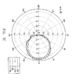
- FIG. 3C shows radiation patterns of the UWB antenna 100 corresponding to different frequencies. As shown in FIG. 3C , the beamwidth of the UWB antenna 100 is relatively wide, and the angles of the beamwidth in both the E-plane and H-plane are between 60 and 70 degrees.
- FIG. 4 shows a schematic view of a UWB-based detecting apparatus for transportation means according to some exemplary embodiments.
- the UWB-based detecting apparatus 400 comprises the UWB antenna 100 and a transceiver 410.
- the UWB-based detecting apparatus 400 is installed at the back of a driver's seat 500, and the transceiver 410 is installed under the driver's seat 500.
- the driver's position is within the range covered by the UWB signal emitted from the UWB antenna 100 and UWB antenna 100 also receives UWB signal reflected from the driver.
- the transceiver 410 analyzes the UWB signal from the UWB antenna 100.
- the driver's physiological status is determined based on the phase difference of the detecting electronic wave reflected from the driver's organs and an electronic wave.
- FIG. 5 shows a schematic view of another UWB-based detecting apparatus for transportation means according to some exemplary embodiments, wherein the UWB antenna 100 is installed in a dashboard.
- the UWB antenna for transportation means emits UWB electronic waves. Therefore, by applying the UWB antenna according to some embodiments, the frequency density of the dispersed power is lowered, which not only alleviates the destructive effect upon human bodies caused by dispersed electronic waves, but also reduces the interference between the emitted UWB electronic waves and the electronic waves emitted from other electronic devices to a negligible degree. In addition, from a practical point of view, the application of UWB electronic waves reduces power consumption, and the manufacturing cost is lowered due to the smaller size of the UWB antenna.
- the cut plane of the UWB electronic waves emitted from the UWB antenna according to some embodiments exhibits an elliptical shape, which can easily cover a driver's body, including the heart area of the driver. Therefore, measurement accuracy of the UWB antenna according to some embodiments is relatively high.
Landscapes
- Health & Medical Sciences (AREA)
- Engineering & Computer Science (AREA)
- Life Sciences & Earth Sciences (AREA)
- Remote Sensing (AREA)
- Radar, Positioning & Navigation (AREA)
- Physics & Mathematics (AREA)
- Surgery (AREA)
- Pathology (AREA)
- Biomedical Technology (AREA)
- Heart & Thoracic Surgery (AREA)
- Medical Informatics (AREA)
- Molecular Biology (AREA)
- Biophysics (AREA)
- Animal Behavior & Ethology (AREA)
- General Health & Medical Sciences (AREA)
- Public Health (AREA)
- Veterinary Medicine (AREA)
- Cardiology (AREA)
- Physiology (AREA)
- Computer Networks & Wireless Communication (AREA)
- General Physics & Mathematics (AREA)
- Pulmonology (AREA)
- Radiology & Medical Imaging (AREA)
- Nuclear Medicine, Radiotherapy & Molecular Imaging (AREA)
- Electromagnetism (AREA)
- Waveguide Aerials (AREA)
- Details Of Aerials (AREA)
Applications Claiming Priority (1)
| Application Number | Priority Date | Filing Date | Title |
|---|---|---|---|
| TW97132026A TWI374573B (en) | 2008-08-22 | 2008-08-22 | Uwb antenna and detection apparatus for transportation means |
Publications (1)
| Publication Number | Publication Date |
|---|---|
| EP2157665A1 true EP2157665A1 (de) | 2010-02-24 |
Family
ID=40810038
Family Applications (1)
| Application Number | Title | Priority Date | Filing Date |
|---|---|---|---|
| EP20090158876 Ceased EP2157665A1 (de) | 2008-08-22 | 2009-04-27 | UWB-Antenne und Detektionsvorrichtung für Transportmittel |
Country Status (3)
| Country | Link |
|---|---|
| US (1) | US20100045546A1 (de) |
| EP (1) | EP2157665A1 (de) |
| TW (1) | TWI374573B (de) |
Cited By (4)
| Publication number | Priority date | Publication date | Assignee | Title |
|---|---|---|---|---|
| EP2680367A3 (de) * | 2012-06-25 | 2014-04-16 | Acer Incorporated | Elektronische Vorrichtung mit Antenne |
| EP2886051A1 (de) * | 2013-12-18 | 2015-06-24 | Hyundai Motor Company | Herzschlagmessvorrichtung, Herzschlagmessverfahren und Fahrerüberwachungssystem |
| WO2019105958A1 (de) * | 2017-12-01 | 2019-06-06 | Ilmsens Gmbh | Anordnung zur überwachung von vitalitätsdaten eines fahrzeugführers |
| DE102020209650A1 (de) | 2020-07-30 | 2022-02-03 | Volkswagen Aktiengesellschaft | Verfahren zum Erfassen von Personen und/oder Objekten im Innenraum eines Kraftfahrzeugs und Kraftfahrzeug |
Families Citing this family (4)
| Publication number | Priority date | Publication date | Assignee | Title |
|---|---|---|---|---|
| PL226423B1 (pl) * | 2012-12-21 | 2017-07-31 | Bumar Elektronika Spółka Akcyjna | Układ pomiarowy sondy |
| US9983300B2 (en) * | 2014-10-17 | 2018-05-29 | Qualcomm Incorporated | Systems, methods, and apparatus for living object protection in wireless power transfer applications |
| CN105024164A (zh) * | 2015-06-29 | 2015-11-04 | 蔡桂钧 | 一种基于u形槽和l型寄生条带的超宽带天线 |
| JP2020120262A (ja) * | 2019-01-23 | 2020-08-06 | ソニーセミコンダクタソリューションズ株式会社 | アンテナおよびミリ波センサ |
Citations (9)
| Publication number | Priority date | Publication date | Assignee | Title |
|---|---|---|---|---|
| US5400041A (en) * | 1991-07-26 | 1995-03-21 | Strickland; Peter C. | Radiating element incorporating impedance transformation capabilities |
| EP0989628A1 (de) * | 1998-09-14 | 2000-03-29 | Ace Technology | Streifenantenne mit gebogener Grundplatte |
| US6195048B1 (en) * | 1997-12-01 | 2001-02-27 | Kabushiki Kaisha Toshiba | Multifrequency inverted F-type antenna |
| WO2001094157A1 (en) * | 2000-06-06 | 2001-12-13 | Automotive Systems Laboratory, Inc. | Occupant detection system |
| US6462701B1 (en) | 2000-11-21 | 2002-10-08 | Time Domain Corporation | System and method for controlling air bag deployment systems |
| WO2004088354A1 (de) * | 2003-03-31 | 2004-10-14 | Siemens Aktiengesellschaft | Kompakter mikrowellen-abstandsensor mit geringer leistungsaufnahme durch leistungsmessung an einem stimulierten empfangsoszillator |
| DE102005020847A1 (de) * | 2005-05-02 | 2006-11-09 | Carsten Dr. Koch | Vorrichtung zur berührungslosen Positionsbestimmung von Körperteilen von Lebewesen im Kraftfahrzeug |
| US20070055164A1 (en) | 2005-09-02 | 2007-03-08 | Industrial Technology Research Institute | Physiological status monitoring system and method |
| US20070096446A1 (en) * | 1995-06-07 | 2007-05-03 | Automotive Technologies International, Inc. | Airbag Deployment Control Based on Contact with Occupant |
Family Cites Families (7)
| Publication number | Priority date | Publication date | Assignee | Title |
|---|---|---|---|---|
| US4771291A (en) * | 1985-08-30 | 1988-09-13 | The United States Of America As Represented By The Secretary Of The Air Force | Dual frequency microstrip antenna |
| US4766440A (en) * | 1986-12-11 | 1988-08-23 | The United States Of America As Represented By The Secretary Of The Navy | Triple frequency U-slot microstrip antenna |
| CA2117223A1 (en) * | 1993-06-25 | 1994-12-26 | Peter Mailandt | Microstrip patch antenna array |
| US5573012A (en) * | 1994-08-09 | 1996-11-12 | The Regents Of The University Of California | Body monitoring and imaging apparatus and method |
| US5940037A (en) * | 1997-04-29 | 1999-08-17 | The Whitaker Corporation | Stacked patch antenna with frequency band isolation |
| US6774853B2 (en) * | 2002-11-07 | 2004-08-10 | Accton Technology Corporation | Dual-band planar monopole antenna with a U-shaped slot |
| US20070066904A1 (en) * | 2005-09-13 | 2007-03-22 | Wiesmann William P | Device and method for a noninvasive cardiac monitor |
-
2008
- 2008-08-22 TW TW97132026A patent/TWI374573B/zh active
-
2009
- 2009-04-27 EP EP20090158876 patent/EP2157665A1/de not_active Ceased
- 2009-08-17 US US12/542,159 patent/US20100045546A1/en not_active Abandoned
Patent Citations (9)
| Publication number | Priority date | Publication date | Assignee | Title |
|---|---|---|---|---|
| US5400041A (en) * | 1991-07-26 | 1995-03-21 | Strickland; Peter C. | Radiating element incorporating impedance transformation capabilities |
| US20070096446A1 (en) * | 1995-06-07 | 2007-05-03 | Automotive Technologies International, Inc. | Airbag Deployment Control Based on Contact with Occupant |
| US6195048B1 (en) * | 1997-12-01 | 2001-02-27 | Kabushiki Kaisha Toshiba | Multifrequency inverted F-type antenna |
| EP0989628A1 (de) * | 1998-09-14 | 2000-03-29 | Ace Technology | Streifenantenne mit gebogener Grundplatte |
| WO2001094157A1 (en) * | 2000-06-06 | 2001-12-13 | Automotive Systems Laboratory, Inc. | Occupant detection system |
| US6462701B1 (en) | 2000-11-21 | 2002-10-08 | Time Domain Corporation | System and method for controlling air bag deployment systems |
| WO2004088354A1 (de) * | 2003-03-31 | 2004-10-14 | Siemens Aktiengesellschaft | Kompakter mikrowellen-abstandsensor mit geringer leistungsaufnahme durch leistungsmessung an einem stimulierten empfangsoszillator |
| DE102005020847A1 (de) * | 2005-05-02 | 2006-11-09 | Carsten Dr. Koch | Vorrichtung zur berührungslosen Positionsbestimmung von Körperteilen von Lebewesen im Kraftfahrzeug |
| US20070055164A1 (en) | 2005-09-02 | 2007-03-08 | Industrial Technology Research Institute | Physiological status monitoring system and method |
Cited By (7)
| Publication number | Priority date | Publication date | Assignee | Title |
|---|---|---|---|---|
| EP2680367A3 (de) * | 2012-06-25 | 2014-04-16 | Acer Incorporated | Elektronische Vorrichtung mit Antenne |
| US8988894B2 (en) | 2012-06-25 | 2015-03-24 | Acer Incorporated | Electronic device |
| EP2886051A1 (de) * | 2013-12-18 | 2015-06-24 | Hyundai Motor Company | Herzschlagmessvorrichtung, Herzschlagmessverfahren und Fahrerüberwachungssystem |
| WO2019105958A1 (de) * | 2017-12-01 | 2019-06-06 | Ilmsens Gmbh | Anordnung zur überwachung von vitalitätsdaten eines fahrzeugführers |
| DE102020209650A1 (de) | 2020-07-30 | 2022-02-03 | Volkswagen Aktiengesellschaft | Verfahren zum Erfassen von Personen und/oder Objekten im Innenraum eines Kraftfahrzeugs und Kraftfahrzeug |
| EP3968050A1 (de) | 2020-07-30 | 2022-03-16 | Volkswagen Ag | Verfahren zum erfassen von personen und/oder objekten im innenraum eines kraftfahrzeugs und kraftfahrzeug |
| US12061250B2 (en) | 2020-07-30 | 2024-08-13 | Volkswagen Aktiengesellschaft | Method for detecting people and/or objects in the interior of a motor vehicle and motor vehicle |
Also Published As
| Publication number | Publication date |
|---|---|
| TW201010179A (en) | 2010-03-01 |
| TWI374573B (en) | 2012-10-11 |
| US20100045546A1 (en) | 2010-02-25 |
Similar Documents
| Publication | Publication Date | Title |
|---|---|---|
| EP2157665A1 (de) | UWB-Antenne und Detektionsvorrichtung für Transportmittel | |
| CN106164698B (zh) | 雷达模块、输送设备以及物体识别方法 | |
| JP6007449B2 (ja) | 自動車用レーダシステムおよびその使用方法 | |
| CN1280141C (zh) | 通过无线电链路获取动态物理过程数据的方法和设备 | |
| EP1548458A2 (de) | In einem Kraftfahrzeug eingebautes Radar | |
| JP4817282B2 (ja) | 電磁信号を送受信するためのセンサ | |
| EP1617234A1 (de) | Fahrzeugradar | |
| EP2584647A3 (de) | Kommunikationsvorrichtung und Antennenstruktur dafür | |
| CN115360501A (zh) | 一种用于77GHz汽车雷达的宽波束天线 | |
| JPH1079616A (ja) | 車載用レーダアンテナ | |
| JP5659587B2 (ja) | レーダ装置、路側器及び車載装置 | |
| WO2022113766A1 (ja) | 電子機器、電子機器の制御方法、及びプログラム | |
| WO1997028459A1 (en) | Vehicle with millimeter-wave radar | |
| US20200072960A1 (en) | Radar device and detection method of target position of radar device | |
| JP2017203736A (ja) | 電波センサおよび検知プログラム | |
| JP2008011385A (ja) | アンテナ装置 | |
| JPH06168400A (ja) | 自動車用レーダ | |
| JP2009047633A (ja) | レーダ装置 | |
| JP5396052B2 (ja) | レーダ送受信機 | |
| JP7678691B2 (ja) | 電子機器 | |
| CN101673876A (zh) | 车用超宽带天线和其检测装置 | |
| WO2019065442A1 (ja) | レーダー装置及び物標検出方法 | |
| TWM406550U (en) | A wireless transmission radar apparatus for car driving in reverse | |
| JP4115477B2 (ja) | アンテナ装置 | |
| JP2021092585A (ja) | 電波センサおよび検知プログラム |
Legal Events
| Date | Code | Title | Description |
|---|---|---|---|
| PUAI | Public reference made under article 153(3) epc to a published international application that has entered the european phase |
Free format text: ORIGINAL CODE: 0009012 |
|
| AK | Designated contracting states |
Kind code of ref document: A1 Designated state(s): AT BE BG CH CY CZ DE DK EE ES FI FR GB GR HR HU IE IS IT LI LT LU LV MC MK MT NL NO PL PT RO SE SI SK TR |
|
| AX | Request for extension of the european patent |
Extension state: AL BA RS |
|
| 17P | Request for examination filed |
Effective date: 20100823 |
|
| 17Q | First examination report despatched |
Effective date: 20110401 |
|
| STAA | Information on the status of an ep patent application or granted ep patent |
Free format text: STATUS: THE APPLICATION HAS BEEN REFUSED |
|
| 18R | Application refused |
Effective date: 20150428 |