EP2157734B1 - Procédé et appareil pour identifier des éléments d'un réseau ayant une grande importance pour l'intégrité du réseau - Google Patents
Procédé et appareil pour identifier des éléments d'un réseau ayant une grande importance pour l'intégrité du réseau Download PDFInfo
- Publication number
- EP2157734B1 EP2157734B1 EP09172247A EP09172247A EP2157734B1 EP 2157734 B1 EP2157734 B1 EP 2157734B1 EP 09172247 A EP09172247 A EP 09172247A EP 09172247 A EP09172247 A EP 09172247A EP 2157734 B1 EP2157734 B1 EP 2157734B1
- Authority
- EP
- European Patent Office
- Prior art keywords
- nodes
- proteins
- data
- network
- identifying
- Prior art date
- Legal status (The legal status is an assumption and is not a legal conclusion. Google has not performed a legal analysis and makes no representation as to the accuracy of the status listed.)
- Expired - Lifetime
Links
Images




Classifications
-
- H—ELECTRICITY
- H04—ELECTRIC COMMUNICATION TECHNIQUE
- H04Q—SELECTING
- H04Q3/00—Selecting arrangements
- H04Q3/0016—Arrangements providing connection between exchanges
- H04Q3/0062—Provisions for network management
- H04Q3/0083—Network planning or design; Modelling of planned or existing networks
-
- G—PHYSICS
- G16—INFORMATION AND COMMUNICATION TECHNOLOGY [ICT] SPECIALLY ADAPTED FOR SPECIFIC APPLICATION FIELDS
- G16B—BIOINFORMATICS, i.e. INFORMATION AND COMMUNICATION TECHNOLOGY [ICT] SPECIALLY ADAPTED FOR GENETIC OR PROTEIN-RELATED DATA PROCESSING IN COMPUTATIONAL MOLECULAR BIOLOGY
- G16B5/00—ICT specially adapted for modelling or simulations in systems biology, e.g. gene-regulatory networks, protein interaction networks or metabolic networks
-
- H—ELECTRICITY
- H04—ELECTRIC COMMUNICATION TECHNIQUE
- H04L—TRANSMISSION OF DIGITAL INFORMATION, e.g. TELEGRAPHIC COMMUNICATION
- H04L41/00—Arrangements for maintenance, administration or management of data switching networks, e.g. of packet switching networks
- H04L41/12—Discovery or management of network topologies
-
- H—ELECTRICITY
- H04—ELECTRIC COMMUNICATION TECHNIQUE
- H04L—TRANSMISSION OF DIGITAL INFORMATION, e.g. TELEGRAPHIC COMMUNICATION
- H04L45/00—Routing or path finding of packets in data switching networks
- H04L45/02—Topology update or discovery
- H04L45/04—Interdomain routing, e.g. hierarchical routing
-
- H—ELECTRICITY
- H04—ELECTRIC COMMUNICATION TECHNIQUE
- H04L—TRANSMISSION OF DIGITAL INFORMATION, e.g. TELEGRAPHIC COMMUNICATION
- H04L45/00—Routing or path finding of packets in data switching networks
- H04L45/12—Shortest path evaluation
-
- H—ELECTRICITY
- H04—ELECTRIC COMMUNICATION TECHNIQUE
- H04L—TRANSMISSION OF DIGITAL INFORMATION, e.g. TELEGRAPHIC COMMUNICATION
- H04L45/00—Routing or path finding of packets in data switching networks
- H04L45/46—Cluster building
-
- H—ELECTRICITY
- H04—ELECTRIC COMMUNICATION TECHNIQUE
- H04L—TRANSMISSION OF DIGITAL INFORMATION, e.g. TELEGRAPHIC COMMUNICATION
- H04L43/00—Arrangements for monitoring or testing data switching networks
- H04L43/16—Threshold monitoring
Definitions
- the present invention relates to methods of analysing networks of interconnected components to identify components of a network which are of high importance for maintaining the network's integrity.
- the invention also relates to apparatus for carrying out such methods.
- networks comprising nodes interconnected by links.
- networks are social interactions where the nodes might be individuals and the links interactions between those individuals, the Internet where nodes are computers and the links are communication links between computers, and proteome data where nodes indicate proteins and links indicate exchanges of metabolites or interactions between the proteins.
- a computer implemented method of identifying target proteins for targeting by drug therapies comprising: obtaining proteome data for an organism to be targeted; storing said proteome data as network data within a computer said network data comprising data defining a plurality of nodes and a plurality of links between said nodes, wherein said nodes are associated with proteins and said links are indicative of protein interactions; processing the stored network data utilizing the computer to determine for each node in the network defined by the stored network data the number of links associated with each node; ordering the nodes in the network defined by stored network data on the basis of the number of links associated with a node; identifying as hub nodes, a set of nodes in the ordered list associated with the greatest numbers of links; and identifying as proteins for targeting by drug therapies, proteins associated with the identified hub nodes.
- an information processing apparatus for identifying target proteins for targeting by drug therapies comprising: a data store configured to store proteome data for an organism to be targeted as network data defining a plurality of nodes and a plurality of links between said nodes wherein said nodes are associated with proteins and said links are indicative of protein interactions; a processing unit operable to process network data stored in said data store to determine for each of the nodes of the network defined by the stored network data, the number of links associated with each node; order the nodes in the network defined by stored network data on the basis of the number of links associated with each node; and identify as hub nodes, a set of nodes in the ordered list associated with the greatest numbers of links; and an output unit operable to output data identifying one or more target proteins for targeting by drug therapies proteins corresponding to the identified hub nodes.
- Figure 1 is a schematic illustration of an embodiment of the present invention.
- data representing a network 1 in the form of nodes (shown as dots in Figure 1 ) interconnected by links (shown as lines in Figure 1 ) is input into a computer 2.
- the data defining a network 1 in this embodiment is taken to be data defining a proteome. That is to say in this embodiment the nodes are indicative of proteins within an organism and the links identify which proteins interact with one another.
- the computer 2 processes the data representing the network to identify within the network a series of nodes and links which are of particular importance for the structural integrity of the network.
- processed data is illustrated by network 3 where the identified nodes of importance for structural integrity of the network are illustrated by circles highlighting some of the nodes.
- a link in the network is highlighted as a critical link by a wavy line in the output data 3.
- the nodes and links identified as being of importance to the structural integrity of the network 1 by the processing of the computer 2 are established in a number of different ways.
- the computer 2 can then output a report 4 identifying the critical nodes and links.
- this report will identify potential drug targets for disrupting the functioning of the organism the proteome 1 represents.
- the computer 2 store data identifying the critical proteins which are utilised and conserved in a host organism, as will be described the potential targets identified by the computer can be filtered so that the report 4 suggests target proteins of the organism represented by the proteome 1 which are not conserved or utilised by a host organism and hence are more likely not to cause side effects in a host. Additionally, the computer 2 can be arranged to include in the report 4 details of agents which are known to attack the functions of the identified critical proteins.
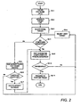
- proteome data 1 for a target organism is acquired utilising conventional techniques.
- This proteome data 1 will identify the proteins present within an organism and also the interactions between those proteins. Identification of the proteins can be achieved using conventional techniques such as mass spectrometry and chromatography etc. Whether different proteins interact can then be established using laboratory techniques such as by manipulating proteins so as to be represented in yeast and seeing whether generated proteins interact.
- data for the proteome has been acquired it is then entered into the computer 2 and stored.
- the computer 2 then (S2-2) processes the input data in the manner described above so as to generate target data which is output in the form of a report 4.
- This report will identify lists of potential targets which by virtue of the analysis of the network topology of the stored proteome data 1 will highlight potential targets for intervention.
- An initial target identified by the report 4 is then selected (S2-3) and checking the report 4 it is determined (S2-4) whether or not any agents are known to react with the identified protein.
- affinity tests can then be run (S2-5) against an expression of the identified protein or proteins to attempt to identify (S2-6) possible compounds that interact with the target. If it is determined that a compound suitable for interacting with the identified target can be found, this data is then added (S2-7) to a compound affinity database for future reference. Alternatively if no such compounds can be found, the next target (S2-8) from the report 4 can be selected for analysis.
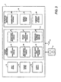
- Figure 3 is a schematic block diagram of the memory of the computer of Figure 1
- the computer 2 is programmed to operate in accordance with programming instructions input for example as data stored in a data storage medium such as a disc 5 and/or as a signal 6 input into the computer 2 for example from a remote database by transmission over a communications network (not shown) such as the Internet.
- a communications network not shown
- the programming instructions comprise instructions to cause the memory of the computer 2 to become configured to process input data defining nodes and links in a network.
- the input data is then processed to generate data identifying critical nodes and links within the network.
- the identified critical nodes and links will then provide information about potential drug targets.
- the memory of the computer 2 When programmed by the programming instructions, the memory of the computer 2 effectively becomes configured into a number of functional units for performing processing operations. Examples of such functional units are shown in Figure 3 .
- the units illustrated in Figure 3 are however, notional and are shown for illustration purposes only to assist understanding; they do not necessarily represent exact units and connections into which the processor, memory etc of the computer 2 become configured.
- an input store 10 is provided for storing data defining network data.
- this network data comprises data identifying proteins in an organism and known interactions between those proteins.
- a target identifier 12 is provided which is arranged to process the network data stored within the input store 10 to identify critical proteins and protein interactions having high importance for the integrity of the proteome. Data identifying the critical proteins is then stored within a target store 14. When the target identifier 12 has stored within the target store 14 data identifying critical proteins, the data within the target store 14 is then filtered utilising a filtration module 16 to identify critical proteins and proteins which are conserved within a host organism.
- an output module 18 utilises the filtered data within the target store 14 and a compound affinity database 20 containing data identifying compounds known to react with proteins to generate and output a report 4 which could be displayed on a screen (not shown) or printed on a printer (not shown) listing the identified critical proteins together with suggested compounds for therapies based on drug targets identified by the target identifier 12.
- the target identifier 12 comprises six sub modules 22-29 each arranged to identify a different type of structure within network data which is indicative of particular components in the network being of high importance for the structural integrity of the network.
- the sub modules comprise a hub identification module 22 which is arranged to identify proteins which interact with large numbers of other proteins; a sub network identification module 24 for identifying connections between sub networks; a bottleneck identification module 26 and a critical path identification module 27 for identifying nodes and links within the network data in the input store 10 which cannot be easily bypassed and hence are of importance for the integrity of the network; a second order node identification module 28 for identifying nodes representing proteins directly interacting with nodes identified by the hub identification module 22, sub network identification module 24 and bottleneck identification module 26; and a structural integrity analysis module 29 for identifying groups of nodes which together significantly affect the structural integrity of the network represented by the data within the input store 10.
- a hub identification module 22 which is arranged to identify proteins which interact with large numbers of other proteins
- a sub network identification module 24 for identifying connections between sub networks
- a bottleneck identification module 26 and a critical path identification module 27 for identifying nodes and links within the network data in the input store 10 which cannot be easily bypassed and hence are of importance for the integrity of
- the targets are filtered by a filtration module 16.
- the filtration module 16 comprises a conservation database 30 and a critical protein store 32.
- the conservation database 30 is arranged to store data identifying similar proteins which are conserved between different organisms.
- data is stored identifying that a particular protein in an organism is substantially a homolog of another protein in a host such as a human.
- the critical protein store 32 is a database storing data identifying critical proteins for the activity of a host.
- the stored targets are likely to be proteins and metabolites which will disrupt the activity of the organism identified by the proteome data and the input store 10 by virtue of the manner of the processing by the target identifier 12.
- targets may be useful for enabling general disinfectants to be identified, if a suitable drug is to be developed it must not only be effective against a target organism, but also must not have excessive side effects.
- the filtration module 16 stores in the conservation database 30 data for identifying which proteins have similar proteins in the host organism. Where a potential target protein is identified which is not present in any form in a host organism it is more likely that a therapy disrupting that particular protein will have limited side effects. If it is not possible to identify a protein which is not conserved as a potential target, at the very least it is desirable to ensure that the targets chosen for further research are unlikely to disrupt the critical systems of a host. By storing data in a critical protein store 32 identifying the critical proteins for a host the list of potential targets can be appropriately filtered to highlight the most promising potential therapies.
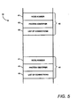
- Figure 5 is a schematic illustration of data stored within the input store 10.
- the data stored within the input store 10 is stored in the form of a number of node records 40 each comprising a node number 41, a protein identifier 42 and a list of connections 43.
- One of these records 40 is stored for each of the proteins within the proteome being analysed.
- the list of connections 43 is a list of node numbers 41 of the node records 40 of the proteins with which the protein identified by the protein identifier 42 for the record 40 is known to interact with.
- Such data can be obtained for a proteome for a particular organism or cell utilising conventional laboratory techniques.
- the protein identifier 42 will be replaced with a different identifier of a network component and the list of connections 42 would be a list of node numbers 41 of components within the network an identified component interacts with.
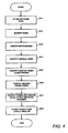
- the.target identifier 12 invokes the hub identification module 22 to identify (S4-2) hub nodes within the network.
- Figure 6 is a schematic illustration of a portion of a network.
- nodes are represented by circles and links between nodes are indicated by lines connecting the circles.
- some nodes such as the node highlighted by a larger circle interact with significantly more nodes than average.
- nodes represent proteins
- proteins such well connected nodes are often indicative of proteins critical to the functioning of an organism. By identifying such nodes, potential drug targets can therefore be found.
- the hub identification module 22 when the hub identification module 22 is invoked, the hub identification module 22 initially determines for each of the node records 40 within the input store 10 the number of entries in the list of connections 43 for each record 40. A list of node numbers is then ordered according to the number of entries in the list of connections 43 in the records 40 identified by the node numbers 41.
- node numbers 41 of nodes which have the greatest numbers of connections and hence are indicative of hubs within the network can be identified.
- Data identifying the node numbers of nodes with the greatest number of connections is then stored in the target store 14.
- the hub identification module 22 in this embodiment is arranged to store within the target store 14 the node numbers identifying the twenty nodes having the greatest number of entries in their list of connections 43.
- the target identifier proceeds to identify potential drug targets in a number of other ways which will now be described in outline.
- the target identifier 12 then (S4-3) invokes the bottleneck identification module 26 to identify within the network represented by data stored within the input store 10 further portions of a network which are important for the structural integrity of that network.
- the bottleneck identification module 26 is arranged to identify nodes in the network which cannot be easily bypassed.
- An example of such a node within a network is illustrated in the exemplary network of Figure 7 where all the paths from the nodes shown as dots in the network of Figure 7 pass through a single node highlighted by a circle. If communication through the node highlighted by the circle is disrupted this then has a significant impact on the integrity of the rest of the network as many nodes will no longer be able to communicate with one another.
- the critical path identification module 27 is then invoked and attempts to identify (S4-4) individual links within the network which are difficult to bypass.
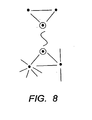
- Figure 8 is a schematic illustration of a portion of a network where a critical link between two nodes is highlighted.
- the highlighted nodes are surrounded by larger circles and the highlighted link is illustrated by a wavy line.
- the sub network identification module 24 is then invoked which then proceeds to identify (S4-5) nodes and links involved in connecting sub networks.
- Figure 9 is a schematic illustration of a network divided into two sub networks.
- the term sub network is taken to mean portions of a network comprising nodes that are more connected to one another than other nodes in the rest of the network.
- the left and right hand sections of the illustrated network 35,36 are examples of sub networks whereas the nodes in the centre of the illustrations 37 are an illustrative example of a bridge between two sub networks. That is to say the nodes shown as highlighted provide a connection between the two sub networks 35,36.
- sub networks When network data is representative of for example a proteome, the existence of sub networks normally identify a series of proteins and protein interactions responsible for different functions within the organism. Thus for example one sub network might involve proteins responsible for controlling cell division, whereas another sub network might identify proteins responsible for controlling energy generation.
- the target store 14 stores data identifying hub nodes, nodes that are difficult to route around and nodes involved in links between sub networks.
- Each of the sets of nodes will have been identified utilising the node and link data defining a network topology stored in the input store 10.
- nodes that are important for network integrity are those nodes that are connected to these identified hubs, nodes that are difficult to avoid and links between sub networks. This is because these nodes interact with nodes of importance and hence if the functioning of these connected nodes is disrupted, the functioning of the other identified nodes of importance may also be effected.
- node 53 is shown as being connected to nodes 50, 51 and 52, all of which can be identified as being of potential importance by virtue of analysis of the network topology. Given the large number of links node 53 has to nodes identifiable as important, enables node 53 to be identified as a potential target for effecting the structural integrity of the network.
- the target identifier 12 invokes the second order node identification module 28.
- the second order node identification module 28 determines for each of the nodes in the network the number of nodes for which identifying data has been stored in the target store 14 which are contained in the list of connections 43 in each of the node records 40. This data is stored for each of the nodes and the second order node identification module 28 then identifies the top twenty nodes connected to the greatest number of other nodes of importance. Thus in this way the second order node identification module 28 is able to identify those nodes which are directly linked to a number of other nodes of importance.
- the target store 14 will have stored within it data identifying the node numbers of all of the nodes identified by the hub identification module 22, sub network identification module 24, bottleneck identification 26, critical path identification module 27 and second order node identification module 28.
- this data identifies individual nodes of importance for maintaining the structural integrity of the network identified by data stored within the input store 10
- the target store 14 will have stored data identifying hub nodes, nodes involved in connections between sub networks, nodes which are difficult to route around, links that are difficult to route around or are involved in connections between sub networks and groups of nodes which together significantly effect the structural integrity of the network defined by the network data stored within the input store 10.
- the output module 18 is invoked (S4-8) which processes the data stored within the target store 14 utilising the filtration module 16 and the compound affinity database 20 to generate a report 4 as will now be described.
- each of the nodes identified by data within the target store 14 is checked against the conservation database 30 and the critical protein store 32 to determine whether the node number identified by data stored within the target store corresponds to the node number 41 of a node record 40 identifying a protein 42 corresponding to a protein stored within the conservation database 30 or the critical protein store 32.
- the output module 28 is able to classify each of the items of data stored within the target store 14 as either relating to critical proteins identified by data within the critical protein store 32, proteins corresponding to proteins identified by the conservation database 30 or neither of these.
- the output module 18 then generates and outputs a report 4 which identifies the proteins corresponding to the node numbers stored within the target store 14 where the proteins which are determined not to appear in either of the conservation database 30 or the critical protein store 32 are listed separately from those which are determined to appear in the conservation database 30 or the critical protein store 32.
- Figure 11 is a schematic illustration of a report 100 generated by the output module 18.
- the report 100 comprises three lists 102, 104, 105 where the first list 102 identifies proteins identified by data stored in the target store 14 for which no corresponding entries are stored within the conservation database 30 or critical protein store 32; a second list 104 which identifies proteins identified by data stored within the target store 14 where any of the nodes or nodes within the groups of nodes are identified by data within the conservation database 30 but not the critical protein store 32; and a third list 105 which identifies the remaining proteins identified by data in the target store 14.
- each of these lists identify for the corresponding list within the report 100 any compounds known to react with proteins identified in the list as identified by data within the compound affinity database 20.
- the output module 18 is able to generate a report where possible target proteins are identified based on an analysis of the topology of network data input into the input store 10.
- a filtration module 16 is described as including a critical protein store 32 identifying critical proteins for the functioning of a host organism.
- the data entered into the critical protein store could be obtained through conventional sources. Alternatively the system described could be utilised to identify critical proteins.
- proteome data for the host organism could be entered into the input store.
- the target identifier 12 would then proceed to identify hubs, nodes and links involved in connection between sub networks, nodes and links that are difficult to route around and second order nodes and groups of nodes which effect the structure integrity of the network represented in the host organism proteome.
- proteome data corresponding to a proteome could be input into the input store 10.
- the computer 2 would then be able to identify additional targets to complement the activity of the known compound or compounds.
- complementary targets for therapy could then be identified.
- the embodiments of the invention described with reference to the drawings comprise computer apparatus and processes performed in computer apparatus, the invention also extends to computer programs, particularly computer programs on or in a carrier, adapted for putting the invention into practice.
- the program may be in the form of source or object code or in any other form suitable for use in the implementation of the processes according to the invention.
- the carrier be any entity or device capable of carrying the program.
- the carrier may comprise a storage medium, such as a ROM, for example a CD ROM or a semiconductor ROM, or a magnetic recording medium, for example a floppy disc or hard disk.
- a storage medium such as a ROM, for example a CD ROM or a semiconductor ROM, or a magnetic recording medium, for example a floppy disc or hard disk.
- the carrier may be a transmissible carrier such as an electrical or optical signal which may be conveyed via electrical or optical cable or by radio or other means.
- the carrier When a program is embodied in a signal which may be conveyed directly by a cable or other device or means, the carrier may be constituted by such cable or other device or means.
- the carrier may be an integrated circuit in which the program is embedded, the integrated circuit being adapted for performing, or for use in the performance of, the relevant processes.
Landscapes
- Engineering & Computer Science (AREA)
- Computer Networks & Wireless Communication (AREA)
- Signal Processing (AREA)
- Physics & Mathematics (AREA)
- Health & Medical Sciences (AREA)
- Life Sciences & Earth Sciences (AREA)
- Bioinformatics & Cheminformatics (AREA)
- Bioinformatics & Computational Biology (AREA)
- Medical Informatics (AREA)
- Physiology (AREA)
- Biophysics (AREA)
- Biotechnology (AREA)
- Evolutionary Biology (AREA)
- General Health & Medical Sciences (AREA)
- Molecular Biology (AREA)
- Spectroscopy & Molecular Physics (AREA)
- Theoretical Computer Science (AREA)
- Management, Administration, Business Operations System, And Electronic Commerce (AREA)
- Data Exchanges In Wide-Area Networks (AREA)
- Computer And Data Communications (AREA)
- Automatic Analysis And Handling Materials Therefor (AREA)
- Information Retrieval, Db Structures And Fs Structures Therefor (AREA)
- Investigating Or Analysing Biological Materials (AREA)
Claims (9)
- Procédé mis en oeuvre par ordinateur pour l'identification de protéines cibles pour ciblage par des thérapies médicamenteuses comprenant les étapes consistant à :obtenir (s2-1) des données de protéome pour un organisme à cibler;stocker (s4-1) lesdites données de protéome sous la forme de données de réseau (40) dans un ordinateur (2), lesdites données de réseau (40) comprenant des données définissant une pluralité de noeuds et une pluralité de liaisons entre lesdits noeuds, lesdits noeuds étant associés à des protéines et lesdites liaisons étant indicatives d'interactions de protéines ;traiter (s4-3) les données de réseau stockées (40) en utilisant l'ordinateur (2) pour déterminer, pour chaque noeud du réseau défini par les données de réseau stockées (40), le nombre de liaisons associées à chaque noeud ;ordonner les noeuds au sein du réseau défini par les données de réseau stockées (40), sur la base du nombre de liaisons associées à un noeud ;identifier en tant que noeuds pivots un jeu de noeuds dans la liste ordonnée associés au plus grand nombre de liaisons ; etidentifier en tant que protéines pour ciblage par des thérapies médicamenteuses, des protéines associées aux noeuds pivots identifiés.
- Procédé selon la revendication 1, comprenant en outre :la fourniture d'une base de données (32) identifiant des protéines critiques pour l'activité d'un organisme hôte ; etl'identification en tant que protéines pour ciblage par des thérapies médicamenteuses, de protéines associées aux noeuds pivots identifiés qui ne correspondent pas aux protéines identifiées par des données dans la base de données (32) identifiant des protéines critiques pour l'activité d'un organisme hôte.
- Procédé selon la revendication 1 ou la revendication 2, comprenant en outre :la fourniture d'une base de données de conservation (30) identifiant des protéines dans un organisme hôte qui sont des homologues de protéines dans un organisme destiné à être ciblé ; etl'identification, en tant que protéines pour ciblage par des thérapies médicamenteuses, de protéines associées aux noeuds pivots identifiés autres que des protéines identifiées par des données dans la base de données de conservation (30).
- Procédé selon l'une quelconque des revendications 1 à 3, comprenant en outre les étapes consistant à :obtenir (s2-1) des données de protéome pour un organisme hôte ;stocker (s4-1) lesdites données de protéome sous la forme de données de réseau (40) dans un ordinateur (2), lesdites données de réseau (40) comprenant des données définissant une pluralité de noeuds et une pluralité de liaisons entre lesdits noeuds, lesdits noeuds étant associés à des protéines et lesdites liaisons étant indicatives d'interactions de protéines ;traiter (s4-3) les données de réseau stockées pour l'organisme hôte (40) en utilisant l'ordinateur (2) pour déterminer, pour chaque noeud du réseau défini par les données de réseau stockées (40), le nombre de liaisons associées à chaque noeud ;ordonner les noeuds au sein du réseau défini par les données de réseau stockées pour l'organisme hôte (40), sur la base du nombre de liaisons associées à un noeud ;identifier en tant que noeuds pivots un jeu de noeuds dans la liste ordonnée associés au plus grand nombre de liaisons ; etidentifier comme protéines pour ciblage par des thérapies médicamenteuses, les protéines associées au noeuds pivots identifiés dans le protéome d'un organisme destiné à être ciblé qui ne sont pas des protéines associées au noeuds pivots identifiés dans le protéome de l'organisme hôte.
- Un procédé de fabrication d'un médicament thérapeutique comprenant :l'identification d'une ou plusieurs protéines cibles pour ciblage par des thérapies médicamenteuses par la mise en oeuvre d'un procédé (s2-2) selon l'une quelconque des revendications précédentes ;l'identification (s2-6) d'un ou de plusieurs composés qui réagissent avec le ou les protéines cibles identifiées ; etla fabrication d'un médicament qui contient des composés identifiés comme réagissant avec les protéines cibles identifiées.
- Un support lisible par ordinateur stockant des instructions interprétables par ordinateur qui, lors de leur exécution par un ordinateur programmable, provoquent la réalisation du procédé selon l'une quelconque des revendications 1 à 4 par l'ordinateur.
- Un dispositif de traitement de l'information (2) pour l'identification de protéines cibles pour ciblage par des thérapies médicamenteuses, comprenant :une mémoire de données (10) configurée pour stocker des données de protéome pour un organisme destiné à être ciblé sous forme de données de réseau (40) définissant une pluralité de noeuds et une pluralité de liaisons entre lesdits noeuds dans lequel lesdits noeuds sont associés à des protéines et lesdits liaisons sont indicatives d'interactions de protéines ;une unité de traitement (22) pouvant fonctionner pour traiter les données de réseau stockées (40) dans ladite mémoire de données (10) pour déterminer, pour chacun parmi les noeuds du réseau définis par les données de réseau stockées (40), le nombre de liaisons associées à chaque noeud ; pour ordonner les noeuds au sein du réseau défini par les données de réseau stockées (40) sur la base du nombre de liaisons associées à chaque noeud ; et pour identifier comme noeuds pivots, un jeu de noeuds dans la liste ordonnée associés aux plus grands nombres de liaisons ; etune unité de sortie pouvant fonctionner pour sortir des données identifiant une ou plusieurs protéines cibles pour ciblage par des thérapies médicamenteuses, les protéines correspondant aux noeuds pivots identifiés.
- Dispositif de traitement d'informations (2) selon la revendication 7, comprenant en outre :une base de données (32) stockant des données identifiant des protéines critiques pour l'activité d'un hôte ;dans lequel l'unité de sortie peut fonctionner afin de sortir en tant que données identifiant une ou plusieurs protéines cibles, les protéines associées aux noeud pivots identifiés par l'unité de traitement (22) qui ne correspond pas aux protéines identifiées par les données dans la base de données (32).
- Dispositif de traitement de l'information (2) selon la revendication 7, comprenant en outre :une base de données de conservation (30) identifiant les protéines d'un organisme hôte qui sont les homologues de protéines dans un organisme à cibler ;dans lequel l'unité de sortie peut fonctionner afin de sortir en tant que données identifiant une ou plusieurs protéines cibles, les protéines associées aux noeuds pivots identifiés par l'unité de traitement (22) qui ne sont pas des protéines identifiées par les données dans la base de données de conservation (30).
Priority Applications (1)
| Application Number | Priority Date | Filing Date | Title |
|---|---|---|---|
| EP10164987.9A EP2363980B1 (fr) | 2002-10-29 | 2003-10-29 | Procédé et appareil pour identifier des éléments d'un réseau ayant une grande importance pour l'intégrité du réseau |
Applications Claiming Priority (4)
| Application Number | Priority Date | Filing Date | Title |
|---|---|---|---|
| GBGB0225109.8A GB0225109D0 (en) | 2002-10-29 | 2002-10-29 | Method of and apparatus for identifying components of a network having high importance for network integrity |
| EP03769681A EP1556819B1 (fr) | 2002-10-29 | 2003-10-29 | Procede et appareil pour identifier des elements d'un reseau ayant une grande importance pour l'integrite du reseau |
| EP08157898A EP1968237B1 (fr) | 2002-10-29 | 2003-10-29 | Procédé et appareil pour identifier des éléments d'un réseau ayant une grande importance pour l'integrité du réseau |
| EP08167881A EP2028792B1 (fr) | 2002-10-29 | 2003-10-29 | Procede et appareil pour identifier des elements d'un reseau ayant une grande importance pour l'integrite du reseau |
Related Parent Applications (4)
| Application Number | Title | Priority Date | Filing Date |
|---|---|---|---|
| EP08167881 Previously-Filed-Application | 2003-10-29 | ||
| EP03769681.2 Division | 2003-10-29 | ||
| EP08157898.1 Division | 2008-06-09 | ||
| EP08167881.5 Division | 2008-10-29 |
Related Child Applications (1)
| Application Number | Title | Priority Date | Filing Date |
|---|---|---|---|
| EP10164987.9 Division-Into | 2010-06-04 |
Publications (3)
| Publication Number | Publication Date |
|---|---|
| EP2157734A2 EP2157734A2 (fr) | 2010-02-24 |
| EP2157734A3 EP2157734A3 (fr) | 2010-05-05 |
| EP2157734B1 true EP2157734B1 (fr) | 2011-12-28 |
Family
ID=9946756
Family Applications (6)
| Application Number | Title | Priority Date | Filing Date |
|---|---|---|---|
| EP03769681A Expired - Lifetime EP1556819B1 (fr) | 2002-10-29 | 2003-10-29 | Procede et appareil pour identifier des elements d'un reseau ayant une grande importance pour l'integrite du reseau |
| EP08167881A Expired - Lifetime EP2028792B1 (fr) | 2002-10-29 | 2003-10-29 | Procede et appareil pour identifier des elements d'un reseau ayant une grande importance pour l'integrite du reseau |
| EP10164987.9A Expired - Lifetime EP2363980B1 (fr) | 2002-10-29 | 2003-10-29 | Procédé et appareil pour identifier des éléments d'un réseau ayant une grande importance pour l'intégrité du réseau |
| EP09172247A Expired - Lifetime EP2157734B1 (fr) | 2002-10-29 | 2003-10-29 | Procédé et appareil pour identifier des éléments d'un réseau ayant une grande importance pour l'intégrité du réseau |
| EP08157898A Expired - Lifetime EP1968237B1 (fr) | 2002-10-29 | 2003-10-29 | Procédé et appareil pour identifier des éléments d'un réseau ayant une grande importance pour l'integrité du réseau |
| EP09172242A Expired - Lifetime EP2154824B1 (fr) | 2002-10-29 | 2003-10-29 | Procédé et appareil pour identifier des éléments d'un réseau ayant une grande importance pour l'intégrité du réseau |
Family Applications Before (3)
| Application Number | Title | Priority Date | Filing Date |
|---|---|---|---|
| EP03769681A Expired - Lifetime EP1556819B1 (fr) | 2002-10-29 | 2003-10-29 | Procede et appareil pour identifier des elements d'un reseau ayant une grande importance pour l'integrite du reseau |
| EP08167881A Expired - Lifetime EP2028792B1 (fr) | 2002-10-29 | 2003-10-29 | Procede et appareil pour identifier des elements d'un reseau ayant une grande importance pour l'integrite du reseau |
| EP10164987.9A Expired - Lifetime EP2363980B1 (fr) | 2002-10-29 | 2003-10-29 | Procédé et appareil pour identifier des éléments d'un réseau ayant une grande importance pour l'intégrité du réseau |
Family Applications After (2)
| Application Number | Title | Priority Date | Filing Date |
|---|---|---|---|
| EP08157898A Expired - Lifetime EP1968237B1 (fr) | 2002-10-29 | 2003-10-29 | Procédé et appareil pour identifier des éléments d'un réseau ayant une grande importance pour l'integrité du réseau |
| EP09172242A Expired - Lifetime EP2154824B1 (fr) | 2002-10-29 | 2003-10-29 | Procédé et appareil pour identifier des éléments d'un réseau ayant une grande importance pour l'intégrité du réseau |
Country Status (6)
| Country | Link |
|---|---|
| EP (6) | EP1556819B1 (fr) |
| AT (4) | ATE551798T1 (fr) |
| AU (1) | AU2003278374A1 (fr) |
| DE (1) | DE60324956D1 (fr) |
| GB (3) | GB0225109D0 (fr) |
| WO (1) | WO2004040497A2 (fr) |
Families Citing this family (3)
| Publication number | Priority date | Publication date | Assignee | Title |
|---|---|---|---|---|
| EP2169568A1 (fr) | 2008-09-17 | 2010-03-31 | OGS Search Limited | Procédé et appareil pour générer un index classé de pages Web |
| US8363570B2 (en) | 2010-01-30 | 2013-01-29 | International Business Machines Corporation | Systems and methods for finding star structures as communities in networks |
| WO2017091822A1 (fr) | 2015-11-25 | 2017-06-01 | Fliri Anton Franz Joseph | Procédés et descripteurs pour comparer des flux d'informations induites par un objet dans une pluralité de réseaux d'interaction |
Family Cites Families (21)
| Publication number | Priority date | Publication date | Assignee | Title |
|---|---|---|---|---|
| US5276789A (en) * | 1990-05-14 | 1994-01-04 | Hewlett-Packard Co. | Graphic display of network topology |
| US5307484A (en) * | 1991-03-06 | 1994-04-26 | Chrysler Corporation | Relational data base repository system for managing functional and physical data structures of nodes and links of multiple computer networks |
| EP0637153B1 (fr) * | 1993-07-30 | 2001-10-31 | International Business Machines Corporation | Méthode et appareil de décomposition automatique d'une topologie de réseau en topologie principale et sous aire |
| US5596703A (en) * | 1993-10-22 | 1997-01-21 | Lucent Technologies Inc. | Graphical display of relationships |
| US5748844A (en) * | 1994-11-03 | 1998-05-05 | Mitsubishi Electric Information Technology Center America, Inc. | Graph partitioning system |
| EP0887749B1 (fr) * | 1997-06-26 | 2008-05-14 | Fraunhofer-Gesellschaft zur Förderung der angewandten Forschung e.V. | Méthode pour découvrir des groupes d'objets qui ont une caractéristique selectionnnable dans une population d'objets |
| US6774899B1 (en) * | 1997-09-18 | 2004-08-10 | Mitsubishi Electric Research Laboratories, Inc. | Drawing graphs using user selectable visual oragnization features and/or other user controlled constraints |
| US6038390A (en) * | 1997-10-21 | 2000-03-14 | Mci Communications Corporation | Method of selecting spans for fiber cut simulations |
| US6437804B1 (en) * | 1997-10-23 | 2002-08-20 | Aprisma Management Technologies, Inc | Method for automatic partitioning of node-weighted, edge-constrained graphs |
| US6065063A (en) | 1998-01-29 | 2000-05-16 | International Business Machines Corp. | Deadlock avoidance method in a computer network |
| US6132969A (en) * | 1998-06-19 | 2000-10-17 | Rosetta Inpharmatics, Inc. | Methods for testing biological network models |
| US6229791B1 (en) | 1998-07-06 | 2001-05-08 | International Business Machines Corporation | Method and system for providing partitioning of partially switched networks |
| US6453241B1 (en) * | 1998-12-23 | 2002-09-17 | Rosetta Inpharmatics, Inc. | Method and system for analyzing biological response signal data |
| AU3482200A (en) * | 1999-02-02 | 2000-08-25 | Bernhard Palsson | Methods for identifying drug targets based on genomic sequence data |
| EP1085693B1 (fr) * | 1999-09-13 | 2009-07-29 | International Business Machines Corporation | Outil pour la visualisation de réseaux |
| EP1158447A1 (fr) * | 2000-05-26 | 2001-11-28 | GMD- Forschungszentrum Informationstechnik GmbH | Procédé d'évaluation d'états de systèmes biologiques |
| WO2001080151A2 (fr) * | 2000-04-14 | 2001-10-25 | Hybrigenics S.A. | Procede de construction, de representation ou d'affichage de cartes d'interactions entre proteines et outil de traitement de donnees dans lequel ledit procede est utilise |
| US6452903B1 (en) | 2000-05-31 | 2002-09-17 | Fujitsu Network Communications, Inc. | Network switch supporting rate-based and credit-based flow control mechanisms on a link-by-link basis |
| FI20001314L (fi) * | 2000-05-31 | 2001-12-01 | Nokia Networks Oy | Telekommunikaatioverkon jaottelu |
| FI20001415L (fi) | 2000-06-14 | 2001-12-15 | Nokia Corp | Reititys tietoliikenneverkossa |
| WO2002011048A2 (fr) * | 2000-07-31 | 2002-02-07 | Agilix Corporation | Visualisation et manipulation de relations biomoleculaires a l'aide d'operateurs graphiques |
-
2002
- 2002-10-29 GB GBGB0225109.8A patent/GB0225109D0/en not_active Ceased
-
2003
- 2003-10-29 GB GB0508596A patent/GB2411268B/en not_active Expired - Fee Related
- 2003-10-29 GB GB0622273A patent/GB2429314A/en not_active Withdrawn
- 2003-10-29 AU AU2003278374A patent/AU2003278374A1/en not_active Abandoned
- 2003-10-29 EP EP03769681A patent/EP1556819B1/fr not_active Expired - Lifetime
- 2003-10-29 AT AT08157898T patent/ATE551798T1/de active
- 2003-10-29 EP EP08167881A patent/EP2028792B1/fr not_active Expired - Lifetime
- 2003-10-29 EP EP10164987.9A patent/EP2363980B1/fr not_active Expired - Lifetime
- 2003-10-29 WO PCT/GB2003/004678 patent/WO2004040497A2/fr not_active Ceased
- 2003-10-29 AT AT09172242T patent/ATE545238T1/de active
- 2003-10-29 AT AT03769681T patent/ATE415666T1/de not_active IP Right Cessation
- 2003-10-29 EP EP09172247A patent/EP2157734B1/fr not_active Expired - Lifetime
- 2003-10-29 EP EP08157898A patent/EP1968237B1/fr not_active Expired - Lifetime
- 2003-10-29 EP EP09172242A patent/EP2154824B1/fr not_active Expired - Lifetime
- 2003-10-29 DE DE60324956T patent/DE60324956D1/de not_active Expired - Lifetime
- 2003-10-29 AT AT09172247T patent/ATE539516T1/de active
Also Published As
| Publication number | Publication date |
|---|---|
| GB2411268A (en) | 2005-08-24 |
| WO2004040497A3 (fr) | 2004-07-29 |
| GB0225109D0 (en) | 2002-12-11 |
| EP1968237A2 (fr) | 2008-09-10 |
| ATE539516T1 (de) | 2012-01-15 |
| AU2003278374A1 (en) | 2004-05-25 |
| EP1968237A3 (fr) | 2008-12-24 |
| EP2157734A3 (fr) | 2010-05-05 |
| EP1968237B1 (fr) | 2012-03-28 |
| GB2429314A (en) | 2007-02-21 |
| EP2154824A1 (fr) | 2010-02-17 |
| ATE545238T1 (de) | 2012-02-15 |
| GB0508596D0 (en) | 2005-06-01 |
| EP1556819A2 (fr) | 2005-07-27 |
| EP2028792A1 (fr) | 2009-02-25 |
| DE60324956D1 (de) | 2009-01-08 |
| GB0622273D0 (en) | 2006-12-20 |
| EP2363980A1 (fr) | 2011-09-07 |
| EP2363980B1 (fr) | 2013-06-12 |
| EP2154824B1 (fr) | 2012-02-08 |
| GB2411268B (en) | 2008-04-16 |
| EP2157734A2 (fr) | 2010-02-24 |
| ATE551798T1 (de) | 2012-04-15 |
| EP1556819B1 (fr) | 2008-11-26 |
| EP2028792B1 (fr) | 2012-08-08 |
| WO2004040497A2 (fr) | 2004-05-13 |
| AU2003278374A8 (en) | 2004-05-25 |
| ATE415666T1 (de) | 2008-12-15 |
Similar Documents
| Publication | Publication Date | Title |
|---|---|---|
| US7466663B2 (en) | Method and apparatus for identifying components of a network having high importance for network integrity | |
| JP2021502625A (ja) | セキュリティ異常を判定するコンピュータ実装方法、コンピュータ・システム、システム、およびコンピュータ・プログラム | |
| CN111382174A (zh) | 多方数据联合查询方法、装置、服务器和存储介质 | |
| CN109376142A (zh) | 数据迁移方法及终端设备 | |
| EP2157734B1 (fr) | Procédé et appareil pour identifier des éléments d'un réseau ayant une grande importance pour l'intégrité du réseau | |
| Kruger et al. | State matching and multiple references in adaptive active automata learning | |
| WO2008078293A1 (fr) | Procédé mis en oeuvre par ordinateur, programme d'ordinateur et système destiné à analyser des enregistrements de données | |
| Tapolcai et al. | Link fault localization using bi-directional M-trails in all-optical mesh networks | |
| EP3493063A1 (fr) | Système et procédé de surveillance | |
| Khoumsi et al. | A formal approach to verify completeness and detect anomalies in firewall security policies | |
| Zahra et al. | A machine learning-based framework for enhancing data security in Cloud of Things | |
| Trifonov et al. | Applying the experience of artificial intelligence methods for information systems cyber protection at industrial control systems | |
| Tapolcai et al. | Signaling free localization of node failures in all-optical networks | |
| Harhalakis et al. | Structured representation of rule-based specifications in CIM using updated Petri nets | |
| Chevreux et al. | Automatic assembly and editing of genomic data | |
| Bourcerie et al. | Algebraically structured colored Petri nets to model sequential processes | |
| US20220329618A1 (en) | Analysis system, method, and program | |
| Janardhanan et al. | Leveraging Minimal Path Sets for Reliability Block Diagram Evaluation | |
| Kalafatidis et al. | C-Shield: A Holistic Solution for Secure End-to-End Kubernetes Multi-Cluster Management and Online Threat Mitigation using LLMs | |
| CN118474015B (zh) | 一种支持自定义路由规则的网关架构方法、装置及存储介质 | |
| Okamoto et al. | Design of virtual-labo-system for metabolic engineering: Development of biochemical engineering system analyzing tool-kit (BEST KIT) | |
| Maruyama et al. | A mechanism for automatically and dynamically changing software components | |
| Ecarot et al. | Learning health systems: An anonymous network routing protocol | |
| Servi | Traversing a Network of Physical Nodes to Attack Functional Components of a Mission Dependency Network | |
| KR20250060617A (ko) | 컨테이너 기반 자동화된 네트워크 보안 정책 생성 방법 및 장치 |
Legal Events
| Date | Code | Title | Description |
|---|---|---|---|
| PUAI | Public reference made under article 153(3) epc to a published international application that has entered the european phase |
Free format text: ORIGINAL CODE: 0009012 |
|
| 17P | Request for examination filed |
Effective date: 20091005 |
|
| AC | Divisional application: reference to earlier application |
Ref document number: 1556819 Country of ref document: EP Kind code of ref document: P Ref document number: 1968237 Country of ref document: EP Kind code of ref document: P Ref document number: 2028792 Country of ref document: EP Kind code of ref document: P |
|
| AK | Designated contracting states |
Kind code of ref document: A2 Designated state(s): AT BE BG CH CY CZ DE DK EE ES FI FR GB GR HU IE IT LI LU MC NL PT RO SE SI SK TR |
|
| PUAL | Search report despatched |
Free format text: ORIGINAL CODE: 0009013 |
|
| AK | Designated contracting states |
Kind code of ref document: A3 Designated state(s): AT BE BG CH CY CZ DE DK EE ES FI FR GB GR HU IE IT LI LU MC NL PT RO SE SI SK TR |
|
| RAP1 | Party data changed (applicant data changed or rights of an application transferred) |
Owner name: E-THERAPEUTICS PLC |
|
| 17Q | First examination report despatched |
Effective date: 20100708 |
|
| GRAP | Despatch of communication of intention to grant a patent |
Free format text: ORIGINAL CODE: EPIDOSNIGR1 |
|
| RIC1 | Information provided on ipc code assigned before grant |
Ipc: H04L 12/24 20060101AFI20110511BHEP Ipc: G06F 17/50 20060101ALI20110511BHEP |
|
| GRAS | Grant fee paid |
Free format text: ORIGINAL CODE: EPIDOSNIGR3 |
|
| GRAA | (expected) grant |
Free format text: ORIGINAL CODE: 0009210 |
|
| AC | Divisional application: reference to earlier application |
Ref document number: 2028792 Country of ref document: EP Kind code of ref document: P Ref document number: 1556819 Country of ref document: EP Kind code of ref document: P Ref document number: 1968237 Country of ref document: EP Kind code of ref document: P |
|
| AK | Designated contracting states |
Kind code of ref document: B1 Designated state(s): AT BE BG CH CY CZ DE DK EE ES FI FR GB GR HU IE IT LI LU MC NL PT RO SE SI SK TR |
|
| REG | Reference to a national code |
Ref country code: GB Ref legal event code: FG4D |
|
| REG | Reference to a national code |
Ref country code: CH Ref legal event code: EP |
|
| REG | Reference to a national code |
Ref country code: AT Ref legal event code: REF Ref document number: 539516 Country of ref document: AT Kind code of ref document: T Effective date: 20120115 |
|
| REG | Reference to a national code |
Ref country code: IE Ref legal event code: FG4D |
|
| REG | Reference to a national code |
Ref country code: DE Ref legal event code: R096 Ref document number: 60339580 Country of ref document: DE Effective date: 20120308 |
|
| REG | Reference to a national code |
Ref country code: NL Ref legal event code: VDEP Effective date: 20111228 |
|
| PG25 | Lapsed in a contracting state [announced via postgrant information from national office to epo] |
Ref country code: SI Free format text: LAPSE BECAUSE OF FAILURE TO SUBMIT A TRANSLATION OF THE DESCRIPTION OR TO PAY THE FEE WITHIN THE PRESCRIBED TIME-LIMIT Effective date: 20111228 Ref country code: SE Free format text: LAPSE BECAUSE OF FAILURE TO SUBMIT A TRANSLATION OF THE DESCRIPTION OR TO PAY THE FEE WITHIN THE PRESCRIBED TIME-LIMIT Effective date: 20111228 Ref country code: GR Free format text: LAPSE BECAUSE OF FAILURE TO SUBMIT A TRANSLATION OF THE DESCRIPTION OR TO PAY THE FEE WITHIN THE PRESCRIBED TIME-LIMIT Effective date: 20120329 |
|
| PG25 | Lapsed in a contracting state [announced via postgrant information from national office to epo] |
Ref country code: BE Free format text: LAPSE BECAUSE OF FAILURE TO SUBMIT A TRANSLATION OF THE DESCRIPTION OR TO PAY THE FEE WITHIN THE PRESCRIBED TIME-LIMIT Effective date: 20111228 Ref country code: CY Free format text: LAPSE BECAUSE OF FAILURE TO SUBMIT A TRANSLATION OF THE DESCRIPTION OR TO PAY THE FEE WITHIN THE PRESCRIBED TIME-LIMIT Effective date: 20111228 |
|
| PG25 | Lapsed in a contracting state [announced via postgrant information from national office to epo] |
Ref country code: CZ Free format text: LAPSE BECAUSE OF FAILURE TO SUBMIT A TRANSLATION OF THE DESCRIPTION OR TO PAY THE FEE WITHIN THE PRESCRIBED TIME-LIMIT Effective date: 20111228 Ref country code: SK Free format text: LAPSE BECAUSE OF FAILURE TO SUBMIT A TRANSLATION OF THE DESCRIPTION OR TO PAY THE FEE WITHIN THE PRESCRIBED TIME-LIMIT Effective date: 20111228 Ref country code: EE Free format text: LAPSE BECAUSE OF FAILURE TO SUBMIT A TRANSLATION OF THE DESCRIPTION OR TO PAY THE FEE WITHIN THE PRESCRIBED TIME-LIMIT Effective date: 20111228 Ref country code: NL Free format text: LAPSE BECAUSE OF FAILURE TO SUBMIT A TRANSLATION OF THE DESCRIPTION OR TO PAY THE FEE WITHIN THE PRESCRIBED TIME-LIMIT Effective date: 20111228 Ref country code: BG Free format text: LAPSE BECAUSE OF FAILURE TO SUBMIT A TRANSLATION OF THE DESCRIPTION OR TO PAY THE FEE WITHIN THE PRESCRIBED TIME-LIMIT Effective date: 20120328 |
|
| PG25 | Lapsed in a contracting state [announced via postgrant information from national office to epo] |
Ref country code: RO Free format text: LAPSE BECAUSE OF FAILURE TO SUBMIT A TRANSLATION OF THE DESCRIPTION OR TO PAY THE FEE WITHIN THE PRESCRIBED TIME-LIMIT Effective date: 20111228 Ref country code: PT Free format text: LAPSE BECAUSE OF FAILURE TO SUBMIT A TRANSLATION OF THE DESCRIPTION OR TO PAY THE FEE WITHIN THE PRESCRIBED TIME-LIMIT Effective date: 20120430 |
|
| RAP2 | Party data changed (patent owner data changed or rights of a patent transferred) |
Owner name: E-THERAPEUTICS PLC |
|
| REG | Reference to a national code |
Ref country code: AT Ref legal event code: MK05 Ref document number: 539516 Country of ref document: AT Kind code of ref document: T Effective date: 20111228 |
|
| REG | Reference to a national code |
Ref country code: DE Ref legal event code: R082 Ref document number: 60339580 Country of ref document: DE Representative=s name: DF-MP, DE |
|
| REG | Reference to a national code |
Ref country code: FR Ref legal event code: CA Effective date: 20120918 |
|
| PG25 | Lapsed in a contracting state [announced via postgrant information from national office to epo] |
Ref country code: DK Free format text: LAPSE BECAUSE OF FAILURE TO SUBMIT A TRANSLATION OF THE DESCRIPTION OR TO PAY THE FEE WITHIN THE PRESCRIBED TIME-LIMIT Effective date: 20111228 |
|
| PLBE | No opposition filed within time limit |
Free format text: ORIGINAL CODE: 0009261 |
|
| STAA | Information on the status of an ep patent application or granted ep patent |
Free format text: STATUS: NO OPPOSITION FILED WITHIN TIME LIMIT |
|
| REG | Reference to a national code |
Ref country code: DE Ref legal event code: R081 Ref document number: 60339580 Country of ref document: DE Owner name: E-THERAPEUTICS PLC, GB Free format text: FORMER OWNER: E-THERAPEUTICS PLC, NEWCASTLE UPON TYNE, GB Effective date: 20121008 Ref country code: DE Ref legal event code: R082 Ref document number: 60339580 Country of ref document: DE Representative=s name: DF-MP, DE Effective date: 20121008 Ref country code: DE Ref legal event code: R081 Ref document number: 60339580 Country of ref document: DE Owner name: E-THERAPEUTICS PLC, LONG HANBOROUGH, GB Free format text: FORMER OWNER: E-THERAPEUTICS PLC, NEWCASTLE UPON TYNE, GB Effective date: 20121008 Ref country code: DE Ref legal event code: R082 Ref document number: 60339580 Country of ref document: DE Representative=s name: DF-MP DOERRIES FRANK-MOLNIA & POHLMAN PATENTAN, DE Effective date: 20121008 |
|
| PG25 | Lapsed in a contracting state [announced via postgrant information from national office to epo] |
Ref country code: IT Free format text: LAPSE BECAUSE OF FAILURE TO SUBMIT A TRANSLATION OF THE DESCRIPTION OR TO PAY THE FEE WITHIN THE PRESCRIBED TIME-LIMIT Effective date: 20111228 |
|
| 26N | No opposition filed |
Effective date: 20121001 |
|
| REG | Reference to a national code |
Ref country code: DE Ref legal event code: R097 Ref document number: 60339580 Country of ref document: DE Effective date: 20121001 |
|
| PG25 | Lapsed in a contracting state [announced via postgrant information from national office to epo] |
Ref country code: AT Free format text: LAPSE BECAUSE OF FAILURE TO SUBMIT A TRANSLATION OF THE DESCRIPTION OR TO PAY THE FEE WITHIN THE PRESCRIBED TIME-LIMIT Effective date: 20111228 |
|
| PG25 | Lapsed in a contracting state [announced via postgrant information from national office to epo] |
Ref country code: ES Free format text: LAPSE BECAUSE OF FAILURE TO SUBMIT A TRANSLATION OF THE DESCRIPTION OR TO PAY THE FEE WITHIN THE PRESCRIBED TIME-LIMIT Effective date: 20120408 |
|
| PG25 | Lapsed in a contracting state [announced via postgrant information from national office to epo] |
Ref country code: MC Free format text: LAPSE BECAUSE OF NON-PAYMENT OF DUE FEES Effective date: 20121031 |
|
| REG | Reference to a national code |
Ref country code: CH Ref legal event code: PL |
|
| PG25 | Lapsed in a contracting state [announced via postgrant information from national office to epo] |
Ref country code: FI Free format text: LAPSE BECAUSE OF FAILURE TO SUBMIT A TRANSLATION OF THE DESCRIPTION OR TO PAY THE FEE WITHIN THE PRESCRIBED TIME-LIMIT Effective date: 20111228 |
|
| PG25 | Lapsed in a contracting state [announced via postgrant information from national office to epo] |
Ref country code: CH Free format text: LAPSE BECAUSE OF NON-PAYMENT OF DUE FEES Effective date: 20121031 Ref country code: LI Free format text: LAPSE BECAUSE OF NON-PAYMENT OF DUE FEES Effective date: 20121031 |
|
| REG | Reference to a national code |
Ref country code: IE Ref legal event code: MM4A |
|
| PG25 | Lapsed in a contracting state [announced via postgrant information from national office to epo] |
Ref country code: IE Free format text: LAPSE BECAUSE OF NON-PAYMENT OF DUE FEES Effective date: 20121029 |
|
| PG25 | Lapsed in a contracting state [announced via postgrant information from national office to epo] |
Ref country code: TR Free format text: LAPSE BECAUSE OF FAILURE TO SUBMIT A TRANSLATION OF THE DESCRIPTION OR TO PAY THE FEE WITHIN THE PRESCRIBED TIME-LIMIT Effective date: 20111228 |
|
| PG25 | Lapsed in a contracting state [announced via postgrant information from national office to epo] |
Ref country code: LU Free format text: LAPSE BECAUSE OF NON-PAYMENT OF DUE FEES Effective date: 20121029 |
|
| PG25 | Lapsed in a contracting state [announced via postgrant information from national office to epo] |
Ref country code: HU Free format text: LAPSE BECAUSE OF FAILURE TO SUBMIT A TRANSLATION OF THE DESCRIPTION OR TO PAY THE FEE WITHIN THE PRESCRIBED TIME-LIMIT Effective date: 20031029 |
|
| REG | Reference to a national code |
Ref country code: FR Ref legal event code: PLFP Year of fee payment: 13 |
|
| REG | Reference to a national code |
Ref country code: FR Ref legal event code: PLFP Year of fee payment: 14 |
|
| REG | Reference to a national code |
Ref country code: FR Ref legal event code: PLFP Year of fee payment: 15 |
|
| REG | Reference to a national code |
Ref country code: FR Ref legal event code: PLFP Year of fee payment: 16 |
|
| PGFP | Annual fee paid to national office [announced via postgrant information from national office to epo] |
Ref country code: DE Payment date: 20201029 Year of fee payment: 18 Ref country code: FR Payment date: 20201027 Year of fee payment: 18 Ref country code: GB Payment date: 20201028 Year of fee payment: 18 |
|
| REG | Reference to a national code |
Ref country code: DE Ref legal event code: R079 Ref document number: 60339580 Country of ref document: DE Free format text: PREVIOUS MAIN CLASS: H04L0012240000 Ipc: H04L0041000000 |
|
| REG | Reference to a national code |
Ref country code: DE Ref legal event code: R119 Ref document number: 60339580 Country of ref document: DE |
|
| GBPC | Gb: european patent ceased through non-payment of renewal fee |
Effective date: 20211029 |
|
| PG25 | Lapsed in a contracting state [announced via postgrant information from national office to epo] |
Ref country code: GB Free format text: LAPSE BECAUSE OF NON-PAYMENT OF DUE FEES Effective date: 20211029 Ref country code: DE Free format text: LAPSE BECAUSE OF NON-PAYMENT OF DUE FEES Effective date: 20220503 |
|
| PG25 | Lapsed in a contracting state [announced via postgrant information from national office to epo] |
Ref country code: FR Free format text: LAPSE BECAUSE OF NON-PAYMENT OF DUE FEES Effective date: 20211031 |