EP2157805A2 - Système de protection multiple et procédé de commande dans un dispositif de communication - Google Patents
Système de protection multiple et procédé de commande dans un dispositif de communication Download PDFInfo
- Publication number
- EP2157805A2 EP2157805A2 EP20090167146 EP09167146A EP2157805A2 EP 2157805 A2 EP2157805 A2 EP 2157805A2 EP 20090167146 EP20090167146 EP 20090167146 EP 09167146 A EP09167146 A EP 09167146A EP 2157805 A2 EP2157805 A2 EP 2157805A2
- Authority
- EP
- European Patent Office
- Prior art keywords
- protection
- unit
- working
- module
- circuit module
- Prior art date
- Legal status (The legal status is an assumption and is not a legal conclusion. Google has not performed a legal analysis and makes no representation as to the accuracy of the status listed.)
- Withdrawn
Links
- 238000004891 communication Methods 0.000 title claims abstract description 20
- 238000000034 method Methods 0.000 title claims description 15
- 238000010586 diagram Methods 0.000 description 6
- 230000000694 effects Effects 0.000 description 6
- 230000008901 benefit Effects 0.000 description 4
- 238000010977 unit operation Methods 0.000 description 2
- 230000005540 biological transmission Effects 0.000 description 1
- 230000003287 optical effect Effects 0.000 description 1
Images




Classifications
-
- H—ELECTRICITY
- H04—ELECTRIC COMMUNICATION TECHNIQUE
- H04Q—SELECTING
- H04Q3/00—Selecting arrangements
- H04Q3/64—Distributing or queueing
- H04Q3/68—Grouping or interlacing selector groups or stages
- H04Q3/685—Circuit arrangements therefor
-
- H—ELECTRICITY
- H04—ELECTRIC COMMUNICATION TECHNIQUE
- H04Q—SELECTING
- H04Q2213/00—Indexing scheme relating to selecting arrangements in general and for multiplex systems
- H04Q2213/13003—Constructional details of switching devices
-
- H—ELECTRICITY
- H04—ELECTRIC COMMUNICATION TECHNIQUE
- H04Q—SELECTING
- H04Q2213/00—Indexing scheme relating to selecting arrangements in general and for multiplex systems
- H04Q2213/13167—Redundant apparatus
-
- H—ELECTRICITY
- H04—ELECTRIC COMMUNICATION TECHNIQUE
- H04Q—SELECTING
- H04Q2213/00—Indexing scheme relating to selecting arrangements in general and for multiplex systems
- H04Q2213/1334—Configuration within the switch
-
- H—ELECTRICITY
- H04—ELECTRIC COMMUNICATION TECHNIQUE
- H04Q—SELECTING
- H04Q2213/00—Indexing scheme relating to selecting arrangements in general and for multiplex systems
- H04Q2213/13341—Connections within the switch
Definitions
- the present invention relates to a communication device with redundant system, and in particular to a protection system for higher reliability of communication lines.
- redundancy of devices and transmission lines is accompanied by the problem of doubling the device volume, power consumption, and price, and therefore, from the viewpoint of global environment protection as well, the adoption of redundancy has its own intrinsic restrictions.
- a shared protection scheme typified by 1:N protection scheme, can be said to be more preferred methods for accomplishing higher reliability.
- a shared protection system which is designed with M:N redundancy of PON interface sections (M protection sections and N working sections) (for example, see Japanese Patent Application Unexamined Publication No. 2008-054278 ).
- M protection sections and N working sections for example, see Japanese Patent Application Unexamined Publication No. 2008-054278 .
- 1:N and 2:N redundancy mathematical analysis has been made (for example, see Ozaki, H., and Kara, A., "Computing the Availability and MTTF of Shared Protection Systems," IEEE CIT 2007, October 2007 ).
- a communication device is designed with M:N component redundancy in which M protection units (#1-#M) are provided for N working units (#1-#N).
- M protection units and N working units are provided with identical circuit modules.
- the working units are normally used.
- an intra-device common unit switches an operation unit from the failure-detected working unit to an available one of the protection units, whereby signal processing is continually performed.
- M:N component redundancy has the advantage that a system can be configured with consideration given to a tradeoff between reliability and costs and/or power consumption (that is, appropriate values can be selected for M and N.)
- M:N component redundancy has a problem as follows. If a large value is selected for M in order to increase reliability, the configuration of the device, particularly the switch section, and its control method become complicated, and the original advantages (low costs and low power consumption) of the M:N component redundancy are lost. Although 2:N component redundancy can achieve higher reliability than 1:N component redundancy, two slots need to be secured for protection units, as well as two switching systems being required to be provided in the communication device. Accordingly, in the case of M:N component redundancy, the configuration is large in scale and complicated, and power consumption is increased. These problems are more significant particularly when a common module in each working and protection unit is large in scale and consumes high power.
- an object of the present invention is to provide a multiple-protection system and control method which can solve the above-described problems and can achieve high reliability while keeping the device configuration simple and small in size and also keeping the control method uncomplicated.
- a multiple-protection system in a communication device includes: a plurality of working units; at least one protection unit; and a unit controller controlling unit switching from a failed working unit to a protection unit, wherein each of the plurality of working units and the protection unit comprises: a plurality of working circuit modules; at least one protection circuit module; and a module controller controlling module switching from a failed working circuit module to a protection circuit module, wherein, when module protection cannot be made by the module switching, the unit switching is performed.
- a multiple-protection method in a communication device which comprises a plurality of working units and at least one protection unit, wherein each of the plurality of working units and the protection unit comprises a plurality of working circuit modules and at least one protection circuit module
- the method includes: when a module failure is detected, performing module switching from a failed working circuit module to a protection circuit module for module protection within a working unit; when the module protection within the working unit cannot be made by the module switching, performing unit switching from a failed working unit to a protection unit for unit protection.
- the effect can be obtained that it is possible to achieve high reliability while keeping the device configuration simple and small in size and also keeping the control method uncomplicated.
- the multiple-protection system is characterized in that redundancy of circuit modules in each device unit is nested in redundancy of device units, whereby a highly reliable network node device can be implemented with a simple device configuration and by an uncomplicated control method.
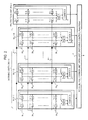
- the communication device has the configuration that working units WU1-1 to WU1-N and protection unit 2 are connected to an intra-device common unit 3.
- Each of the working units WU1-1 to WU1-N inputs n external input signals (IN 11 -IN 1n , IN 21 -IN 2n , ⁇ IN N1 - IN Nn ) and outputs its output signal to the intra-device common unit 3.
- the working unit WU1-J is provided with input interfaces (IFs) 11-J-1 to 11-J-n to which its n external input signals IN J1 -IN Jn are input, respectively.
- the output signals of the input interfaces (IFs) 11-J-1 to 11-J-n are normally connected to working circuit modules 1-2-J-1 to 12-J-n, respectively, and, in case of a failure occurring in a working circuit module, are selectively connected to protection circuit modules 13-J-1 and 13-J-2 through selective switches.
- the protection circuit modules 13-J-1 and 13-J-2 are the same internal circuit as the working circuit modules 12-J-1 to 12-J-n.
- the output signals of these circuit modules are processed by a common module 14-J having a module switching control function.
- the output signal of the common module 14-J is output to an intra-device common unit 3 having a unit switching control function.
- the protection unit 2 has the same circuit as the working unit WU1-J. More specifically, the protection unit 2 is provided with input interfaces (IPs) 21-1 to 21-n, which are connected to the protection lines 4-1 to 4-n, respectively.
- IPs input interfaces
- the output signals of the input interfaces 21-1 to 21-n are normally connected to working circuit modules 22-1 to 22-n, respectively, and, in case of a failure occurring in a working circuit module, are selectively connected to protection circuit modules 23 -1 and 23-2 through selective switches.
- the protection circuit modules 23-1 and 23-2 are the same internal circuit as the working circuit modules 22-1 to 22-n. After signal processing by these circuit modules (22-1 to 22-n, 23-1 and 23-3), the output signals of these circuit modules are processed by a common module 24 having the module switching control function. The output signal of the common module 24 is output to the intra-device common unit 3.
- the infra-device common unit 3 has the unit switching control function of switching between any one of the working units 1-1 to 1-N and the protection unit 2 in case of occurrence of a unit failure.
- the working unit WU1-J is provided with input interfaces 11-J-1 to 11-J-n to which its n external input signals IN J1 -IN Jn are input through selective switches SW-J-1 to SW-J-n, respectively.
- the output signal of the input interface 11-J-1 can be selectively connected to the working circuit module 12-J-1 or an available one of the protection modules 13-J-1 and 13-J-2 through selective switches SW1-J-1 and SW2-J-1.
- the output signal of the working circuit module 1-2-J-1 or the selected protection module is processed by the common module 14-J.
- the respective output signals of other input interfaces 11-J-2 to 11-J-n can be selectively connected to the corresponding working circuit modules 12-J-2 to 12-J-n or an available one of the protection modules 13-J-1 and 13-J-2 through selective switches SW1-J-2 to SW1-J-n and SW2-J-2 to SW2-J-n.
- the respective output signals of the working circuit modules 12-J-2 to 12-J-n which may include selected protection module(s) instead of failed working circuit module(s), are processed by the common module 14-J.
- the common unit 14-J functionally includes a module failure detector 14-J1 and a module switch controller 14-J2.
- the module failure detector 14-J1 monitors the working circuit modules 12-J-1 to 12-J-n and, when detecting a failure in a working circuit module, informs the module switch controller 14-J2 of failure occurrence in the working circuit module and then the module switch controller 14-J2 activates a corresponding selective switch for protection.
- the module switch controller 14-J2 checks which one of the protection modules 13-J-1 and 13-J-2 is available and powers on the available protection module. Then the module switch controller 14-J2 switches a corresponding one of the selective switches SW1-J-1 and SW2-J-1 from normal position to protection position so as to change a connection of the output signal of the input interface 11-J-1 to the available protection module 13-J-1 or 13-J-2. At the same time, the module switch controller 14-J2 may power off the failed working circuit module.
- the internal circuit of the protection unit 2 is the same as that of the working circuit unit WU1-J.
- the input interfaces 21-1 to 21-n correspond to the input interfaces 11-J-1 to 11-J-n
- the working circuit modules 22-1 to 22-n to the working circuit modules 12-J-1 to 12-J-n
- the protection circuit modules 23-1 and 23-2 to the protection circuit modules 13-J-1 and 13-J-2
- the common module 24 to the common module 14-J, respectively.
- the intra-device common unit 3 functionally includes a unit switch controller 30.
- the unit switch controller 30 activates the selective switches to switch unit operation from the failed working circuit unit to the protection circuit unit 2.
- the intra-device common unit 3 switches the selective switches SW-J-1 to SW-J-n from normal position to protection position, so that the n external input signals IN J1 -IN Jn are transferred directly to the protection unit 2 through the protection line 4-1 to 4-n.
- the intra-device common unit 3 may power off the failed working circuit unit WU1-J. In this manner, the protection unit 2 operates instead of the failed working circuit unit.
- the multiple-protection control is performed by a combination of the common module 14-J of each working unit WU1-J and the intra-device common unit 3.
- the selective switches SW1-J-2 to SM1-J-n and SW2-J-2 to SW2-J-n are set at the normal position to transfer the n external input signals IN J1 -IN Jn to the working circuit modules 12-J-1 to 12-J-n, respectively.
- the respective working circuit modules 12-J-1 to 12-J-n perform signal processing of the n external input signals IN J1 -IN Jn and output processed signals to the common module 14-J.
- the module failure detector 14-J1 of the common module 14-J monitors the output signals of the working circuit modules 12-J-1 to 12-J-n to check whether a circuit module failure occurs (Step S101).
- Step S101 When a failure is detected in any one (i-th) of the working circuit modules 12-J-1 to 12-J-n (Step S101: YES), the module switch controller 14-J2 of the common module 14-J checks whether at least one of the protection modules 13-J-1 and 13-J-2 is available (Step S102).
- Step S102 When a protection module is available (Step S102: YES), the module switch controller 14-J2 activates a corresponding one of the selective switches SW1-J-i and SW2-J-1 to separate the failed working circuit module 12-J-i and connect a corresponding external input signal IN Ji to an available protection module, so that signal processing of the corresponding external input signal IN Ji is performed by an available one of the protection circuit modules 13-J-1 and 13-J-2, instead of the failed working circuit module 12-J-i (Step S103).
- this protection module processing (Step S102 and Step S103) is allowed only when at least one protection circuit module operates normally and is not in use.
- the common module 14-J notifies the intra-device common unit 3 of a unit failure.
- the unit switch controller 30 of the intra-device common unit 3 checks whether the protection unit 2 is available (Step S104). When the protection unit 2 is available (Step S104: YES), the unit switch controller 30 activates the selective switches SW-J-1 to SW-J-n so that switching to the protection unit 2 (unit switching) is performed (Step S105).
- this protection unit processing (Step S104 and Step S105) is allowed only when the protection unit 2 operates normally and is not in use.
- the protection unit 2 also has the protection circuit modules 23-1 and 23-2. Accordingly, if a failure occurs in the working circuit modules 22-1 to 22-n, then switching is performed within the protection unit 2, whereby signal processing can be continually performed. Actually, after the unit switching (Step S105), the failed working unit is repaired or replaced with a new one and then the unit operation is switched from the protection unit 2 to the repaired or new working unit, so that the signal processing is continued normally.
- multiple-protection switching control in two steps is performed. Specifically, when a circuit module fails within a unit, module switching is performed first within the unit, thereby protecting the signal processing. Then, only when this protection within the unit is impossible, unit switching to the protection unit 2 is performed. In other words, the module protection has precedence over the unit protection.
- the above-described module protection may be implemented by programs running on a program-controlled processor in each of working and protection circuit modules.
- the above-described unit protection may be implemented by programs running on a program-controlled processor in each of working and protection units.
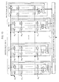
- FIG. 5 shows a case where no failure occurs.
- signal processing is performed by the working circuit module 12-1-1.
- the working circuit module 12-1-1 fails, module switching is performed within the working unit WU1-1, so that signal processing is performed by the first protection circuit module 13-1-1 as shown in FIG. 6 . If the first protection circuit module 13-1-1 is in use or fails, the second protection circuit module 13-1-2 is used, which is shown in FIG. 7 .
- the first protection circuit module 23-1 When the working circuit module 22-1 in the protection unit 2 fails, the first protection circuit module 23-1, or the second protection circuit module 23-2 if the first one is in use or fails, in the protection unit 2 is used. This is shown in FIGS. 9 and 10 .
- the redundancy of the circuit modules closed within a unit is non-repairable system redundancy. That is, even when switching is performed within a unit due to the occurrence of a failure, there is no need to perform replacement or repair immediately. When a failure cannot be handled by the redundancy within the unit, unit switching is performed, and replacement or repair of the unit is made.
- the multiple-redundancy scheme for circuit modules and device units according to the present exemplary embodiment can solve the problems described earlier and achieve high reliability while keeping the device configuration simple and small in size and also keeping the control uncomplicated.
- non-repairable module redundancy is adopted within each device unit of the communication device, which is embedded in repairable unit redundancy (protection unit 2).
- the higher-density device can be made by allocating the reduced volume of the protection unit 2 to a working unit. More specifically, a working slot is implemented in place for the slot for protection unit made available, whereby higher density can be accomplished.
- the present exemplary embodiment also has the effect that lower power consumption of the entire system can be accomplished by making a configuration such that no power is supplied to unused ones of the protection circuit modules and protection component.
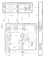
- FIG. 11 is a block diagram showing an example of the configuration of a communication device according to a second exemplary embodiment of the present invention. Like this configuration according to the second exemplary embodiment of the present invention shown in FIG. 11 , it is also possible to make a configuration such that protection circuit modules 13-J-1 and 13-J-2 are provided as options and allowed to serve as working circuit modules by using selectors 16-J-1 and 16-J-2 so that all circuit modules are used as working circuit modules.
- each of the selectors 16-J-1 and 16-J-2 controlled by the common module 14-J, selects one of a transferred external input signal for a failed working circuit module and an original external input signal received from a corresponding one of interfaces 15-J-1 and 15-J-2. Accordingly, when the selector selects the original external, the corresponding protection circuit module serves as a working circuit module. It is the same with the protection unit 2 such that protection circuit modules 23-1 and 23-2 are provided as options and allowed to serve as working circuit modules by using selectors 26-1 and 26-2 so that all circuit modules are used as working circuit modules. Therefore a description will be provided for a working unit.
- the use of the protection circuit modules 13-1 and 13-2 are made optional. Thereby, the effect can be obtained that a flexible device configuration can be made with consideration given to the required number of lines to be accommodated and reliability. Since the module switching between circuit modules is performed according to closed control within a unit, the effect is also obtained that the present invention can be applied only by revising a unit, without changing a communication device.
- module protection and unit protection may be implemented by programs running on program-controlled processors in each circuit module and each unit.
- circuit modules can also be accomplished within a single integrated circuit or across a plurality of coupled integrated circuits. Although shown in the above-described examples is a configuration provided with two protection circuit modules per unit and one protection unit, it is also possible to make a configuration with any number of protection modules and any number of protection units.
Landscapes
- Engineering & Computer Science (AREA)
- Computer Networks & Wireless Communication (AREA)
- Data Exchanges In Wide-Area Networks (AREA)
Applications Claiming Priority (1)
| Application Number | Priority Date | Filing Date | Title |
|---|---|---|---|
| JP2008211266A JP2010050586A (ja) | 2008-08-20 | 2008-08-20 | 通信装置及びそれに用いる装置コンポーネント複合冗長化方法 |
Publications (1)
| Publication Number | Publication Date |
|---|---|
| EP2157805A2 true EP2157805A2 (fr) | 2010-02-24 |
Family
ID=41343498
Family Applications (1)
| Application Number | Title | Priority Date | Filing Date |
|---|---|---|---|
| EP20090167146 Withdrawn EP2157805A2 (fr) | 2008-08-20 | 2009-08-04 | Système de protection multiple et procédé de commande dans un dispositif de communication |
Country Status (4)
| Country | Link |
|---|---|
| US (1) | US20100046365A1 (fr) |
| EP (1) | EP2157805A2 (fr) |
| JP (1) | JP2010050586A (fr) |
| CN (1) | CN101656899A (fr) |
Families Citing this family (5)
| Publication number | Priority date | Publication date | Assignee | Title |
|---|---|---|---|---|
| US9037296B2 (en) * | 2011-09-07 | 2015-05-19 | Lg Electronics Inc. | Robot cleaner, and system and method for remotely controlling the same |
| US9054955B2 (en) | 2012-12-30 | 2015-06-09 | Doron Handelman | Apparatus and methods for enabling recovery from failures in optical networks |
| WO2014140894A2 (fr) | 2013-03-15 | 2014-09-18 | Bioven 3 Limited | Protéines de synthèse à auto-assemblage |
| US9344187B2 (en) | 2013-09-17 | 2016-05-17 | Doron Handelman | Apparatus and methods for enabling recovery in optical networks |
| CN103970629A (zh) * | 2014-06-05 | 2014-08-06 | 俞泽生 | 一种具有冗余电路的设备的协作方法 |
Citations (2)
| Publication number | Priority date | Publication date | Assignee | Title |
|---|---|---|---|---|
| JP2008054278A (ja) | 2006-07-26 | 2008-03-06 | Nec Corp | Ponシステム、局側装置及びそれらに用いる冗長化方法 |
| JP2008211266A (ja) | 2008-06-11 | 2008-09-11 | Renesas Technology Corp | 半導体装置の製造方法 |
Family Cites Families (5)
| Publication number | Priority date | Publication date | Assignee | Title |
|---|---|---|---|---|
| JPH0816422A (ja) * | 1994-07-04 | 1996-01-19 | Fujitsu Ltd | バス通信方法及びバス通信システム |
| US20030026294A1 (en) * | 2001-07-20 | 2003-02-06 | Chul-Hee Lee | Subscribers-switching device and method of asymmetrical digital subscriber lines |
| JP2006074371A (ja) * | 2004-09-01 | 2006-03-16 | Nippon Telegr & Teleph Corp <Ntt> | 故障時復旧方法、冗長化構成方法、パケット処理装置 |
| JP2006115177A (ja) * | 2004-10-14 | 2006-04-27 | Nippon Telegr & Teleph Corp <Ntt> | リコンフィギュラブルボード搭載パケット処理装置 |
| US7675904B2 (en) * | 2005-01-28 | 2010-03-09 | Inventec Multimedia & Telecom Corporation | VoIP terminal capable of having conversation through both internet and PSTN |
-
2008
- 2008-08-20 JP JP2008211266A patent/JP2010050586A/ja active Pending
-
2009
- 2009-08-04 EP EP20090167146 patent/EP2157805A2/fr not_active Withdrawn
- 2009-08-20 CN CN200910166252A patent/CN101656899A/zh active Pending
- 2009-08-20 US US12/544,632 patent/US20100046365A1/en not_active Abandoned
Patent Citations (2)
| Publication number | Priority date | Publication date | Assignee | Title |
|---|---|---|---|---|
| JP2008054278A (ja) | 2006-07-26 | 2008-03-06 | Nec Corp | Ponシステム、局側装置及びそれらに用いる冗長化方法 |
| JP2008211266A (ja) | 2008-06-11 | 2008-09-11 | Renesas Technology Corp | 半導体装置の製造方法 |
Non-Patent Citations (1)
| Title |
|---|
| OZAKI, H.; KARA, A.: "Computing the Availability and MTTF of Shared Protection Systems", IEEE CIT 2007, October 2007 (2007-10-01) |
Also Published As
| Publication number | Publication date |
|---|---|
| US20100046365A1 (en) | 2010-02-25 |
| JP2010050586A (ja) | 2010-03-04 |
| CN101656899A (zh) | 2010-02-24 |
Similar Documents
| Publication | Publication Date | Title |
|---|---|---|
| US8554949B2 (en) | Customer traffic forwarding continues while control plane is reset | |
| CN110351174A (zh) | 一种模块冗余的安全计算机平台 | |
| US20110169522A1 (en) | Fault-tolerant multi-chip module | |
| CN103064769A (zh) | 双热备服务器系统 | |
| US20100046365A1 (en) | Multiple-protection system and control method in a communication device | |
| CN108304030A (zh) | 一种多路服务器时钟系统、多路服务器及其控制方法 | |
| EP2535817B1 (fr) | Système de traitement d informations | |
| CN112486896A (zh) | 机架式交换机的业务卡管理装置及方法、设备和介质 | |
| US20140070616A1 (en) | Power conversion output architecture | |
| US7433763B2 (en) | Power management logic that reconfigures a load when a power supply fails | |
| JP6429188B2 (ja) | 中継装置 | |
| US10539992B2 (en) | Redundant power extender | |
| US7656789B2 (en) | Method, system and storage medium for redundant input/output access | |
| CN114257462A (zh) | 以太网供电接口的断电 | |
| US7287187B2 (en) | Method and apparatus for supplying redundant power | |
| HK1136433A (en) | Multiple-protection system and control method in a communication device | |
| JP3621634B2 (ja) | 冗長構成切替システム | |
| US12119867B2 (en) | Transmission apparatus and transmission method | |
| CN105278651A (zh) | 一种冗余控制系统 | |
| KR20120010878A (ko) | 바이패스 기능을 가진 네트워크 장치와 바이패스 모듈 | |
| CN114978787A (zh) | 以太网供电接口的断电 | |
| CN120743200B (zh) | 存储节点的管理方法和电子设备 | |
| CN121603088A (zh) | 一种基于fpga自刷新的星用路由转发器 | |
| CN109861871B (zh) | 具备自监控功能的以太网旁路设备 | |
| CN121858366A (zh) | 基于ai服务器超节点的gpu冗余布置方法、装置、设备介质 |
Legal Events
| Date | Code | Title | Description |
|---|---|---|---|
| PUAI | Public reference made under article 153(3) epc to a published international application that has entered the european phase |
Free format text: ORIGINAL CODE: 0009012 |
|
| AK | Designated contracting states |
Kind code of ref document: A2 Designated state(s): AT BE BG CH CY CZ DE DK EE ES FI FR GB GR HR HU IE IS IT LI LT LU LV MC MK MT NL NO PL PT RO SE SI SK SM TR |
|
| AX | Request for extension of the european patent |
Extension state: AL BA RS |
|
| REG | Reference to a national code |
Ref country code: HK Ref legal event code: DE Ref document number: 1136433 Country of ref document: HK |
|
| STAA | Information on the status of an ep patent application or granted ep patent |
Free format text: STATUS: THE APPLICATION HAS BEEN WITHDRAWN |
|
| 18W | Application withdrawn |
Effective date: 20140623 |
|
| REG | Reference to a national code |
Ref country code: HK Ref legal event code: WD Ref document number: 1136433 Country of ref document: HK |