EP2157845A1 - Appareil d'automatisation - Google Patents
Appareil d'automatisation Download PDFInfo
- Publication number
- EP2157845A1 EP2157845A1 EP08014456A EP08014456A EP2157845A1 EP 2157845 A1 EP2157845 A1 EP 2157845A1 EP 08014456 A EP08014456 A EP 08014456A EP 08014456 A EP08014456 A EP 08014456A EP 2157845 A1 EP2157845 A1 EP 2157845A1
- Authority
- EP
- European Patent Office
- Prior art keywords
- module
- parts
- module parts
- automation device
- assembly
- Prior art date
- Legal status (The legal status is an assumption and is not a legal conclusion. Google has not performed a legal analysis and makes no representation as to the accuracy of the status listed.)
- Withdrawn
Links
- 230000000712 assembly Effects 0.000 claims description 17
- 238000000429 assembly Methods 0.000 claims description 17
- 230000005540 biological transmission Effects 0.000 description 2
- 230000008878 coupling Effects 0.000 description 2
- 238000010168 coupling process Methods 0.000 description 2
- 238000005859 coupling reaction Methods 0.000 description 2
- 238000004891 communication Methods 0.000 description 1
- 238000010586 diagram Methods 0.000 description 1
- 230000001747 exhibiting effect Effects 0.000 description 1
- 238000009434 installation Methods 0.000 description 1
- 238000000034 method Methods 0.000 description 1
- 239000000203 mixture Substances 0.000 description 1
Images


Classifications
-
- H—ELECTRICITY
- H05—ELECTRIC TECHNIQUES NOT OTHERWISE PROVIDED FOR
- H05K—PRINTED CIRCUITS; CASINGS OR CONSTRUCTIONAL DETAILS OF ELECTRIC APPARATUS; MANUFACTURE OF ASSEMBLAGES OF ELECTRICAL COMPONENTS
- H05K7/00—Constructional details common to different types of electric apparatus
- H05K7/14—Mounting supporting structure in casing or on frame or rack
- H05K7/1462—Mounting supporting structure in casing or on frame or rack for programmable logic controllers [PLC] for automation or industrial process control
- H05K7/1475—Bus assemblies for establishing communication between PLC modules
- H05K7/1478—Bus assemblies for establishing communication between PLC modules including a segmented bus
-
- H—ELECTRICITY
- H05—ELECTRIC TECHNIQUES NOT OTHERWISE PROVIDED FOR
- H05K—PRINTED CIRCUITS; CASINGS OR CONSTRUCTIONAL DETAILS OF ELECTRIC APPARATUS; MANUFACTURE OF ASSEMBLAGES OF ELECTRICAL COMPONENTS
- H05K7/00—Constructional details common to different types of electric apparatus
- H05K7/14—Mounting supporting structure in casing or on frame or rack
- H05K7/1438—Back panels or connecting means therefor; Terminals; Coding means to avoid wrong insertion
- H05K7/1439—Back panel mother boards
- H05K7/1441—Back panel mother boards with a segmented structure
-
- H—ELECTRICITY
- H05—ELECTRIC TECHNIQUES NOT OTHERWISE PROVIDED FOR
- H05K—PRINTED CIRCUITS; CASINGS OR CONSTRUCTIONAL DETAILS OF ELECTRIC APPARATUS; MANUFACTURE OF ASSEMBLAGES OF ELECTRICAL COMPONENTS
- H05K7/00—Constructional details common to different types of electric apparatus
- H05K7/14—Mounting supporting structure in casing or on frame or rack
- H05K7/1462—Mounting supporting structure in casing or on frame or rack for programmable logic controllers [PLC] for automation or industrial process control
- H05K7/1465—Modular PLC assemblies with separable functional units
Definitions
- the invention relates to an automation device which has a plurality of arranged on a mounting rail assemblies, wherein on the rear wall of each module a plurality of contacts exhibiting module module part is provided which cooperates electrically and mechanically with a connecting element also having a plurality of contacts.
- An automation device of the type mentioned is from the DE 42 25 573 C2 known.
- Each assembly of this automation device has a substantially U-shaped module bus module part, which is electrically and mechanically connected to produce a bus connection with an adjacent module with a likewise substantially U-shaped connection bus module part.
- the base and the legs of a connection bus module part bridge the distance between one leg of a module bus module part from an adjacent leg of an adjacent module.
- the assembly of the automation device is preferably carried out in such a way that in each case a leg of the connection bus module part is inserted into the right leg of the modules, so that the right leg of the respective connection bus module part protrudes from the back right of the modules.
- the assemblies nach- and side by side swung on a mounting rail, forcibly by the pivoting the electrical connection of adjacent modules is made.
- the legs of the substantially U-shaped module bus module parts of the assemblies always have the same distance from the nearest side wall of the respective module, whereby assemblies of different widths can be plugged onto the connection bus module parts.
- the present invention has for its object to provide an automation device of the type mentioned, which allows a substantially optimal assignment of the mounting rail with modules of the programmable controller.
- any width can be used, with "slot or installation losses" are avoided.
- the entire width of any width support rail can be used to arrange assemblies on this.
- different physical topologies of a backplane bus of an automation device can be realized.
- connection structures in the form of a star and / or bus connection can be realized, with a mixture of the various structures being possible.
- a "gridless" modular system design is provided wherein miniaturization (pitch reduction) in ratio phases over a product family life is possible. Substantially full slot utilization is ensured because "slot losses" are avoided.
- a ("growing") point-to-point coupling, a bus coupling, a HUB or a switch structure can be realized. Only one assembly family is required for different, graded performance classes.
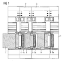
- FIG. 1 1 is a mounting rail on which assemblies 2, 3 of an automation device are arranged and mounted.
- the automation device usually has at least one central or CPU module and a plurality of digital input / output, analog input / output, communication and / or further functional modules for controlling a technical process.
- the assemblies 2, 3 are each provided with an assembly module part, not shown here, which is electrically connected to a printed circuit board, which in the case where the assemblies 2, 3 are mounted on the mounting rail 1, in a connection module part 4, 5, 6 engages and cooperates with this electrically and mechanically.
- the connection module parts 4, 5, 6 are designed to be displaceable on the support rail 1, which means that adjacent connection module parts 4, 5, 6 can be positioned at any distance on the support rail 1, which is in the FIG. 1 represented by the symbols " ⁇ ".
- connection module parts 4, 5, 6 each have a leg 4a, 5a, 6a provided with a plurality of contacts, wherein in the present example the legs 4a, 5a engage in corresponding legs of the assemblies 2, 3 and interact electrically and mechanically.
- connection module parts 4, 5, 6 are each provided with a flexible multi-core connecting means 7, 8, 9 in the form of a flexible printed circuit board or a flexible multi-core cable 7, 8, 9, via which the respective connection module part 4, 5, 6 for the realization of a so-called HUB structure is connected to a central unit.
- the distances between adjacent connection module parts 4, 5, 6 are selected as a function of the module widths and thus these distances can be adapted to the module widths.
- FIG. 2 and FIG. 4 1 shows an embodiment with essentially U-shaped connection module parts 10, 11, 12, each having two legs 10a, 10b, 11a, 11b, 12a, 12b and a base B. Not shown here, which are electrically connected to a printed circuit board.
- Module parts of assemblies 16, 17 are also substantially U-shaped with two legs and a base formed, wherein the connection module parts 10, 11, 12 respectively bridge the distance between two adjacent legs of two adjacent modules in assembled automation device.
- the connection module parts 10, 11, 12 cooperate with the assembly module parts electrically and mechanically together, wherein further the connection module parts 10, 11, 12 each have a flexible multi-core cable 13, 14, 15 are connected to a central assembly.
- Such a connection structure enables a redundant HUB structure.
- the assembly 16 is connected to both the first and second central units. Accordingly, in the case that the cable 15 is connected to a third central unit, the assembly 17 is connected to both the second and the third central unit.
- connection module part 10 is provided for connecting another to the module 16 adjacent and the connection module part 12 for connecting an assembly 17 adjacent module.
- the respective connection module part 10, 11, 12 bridges the distance between adjacent legs of adjacent assemblies.
- connection module parts 18, 19, 20 which have no flexible cables, wherein the connection module parts 18, 19, 20 are also positioned at an arbitrary distance on the support rail 1.
- Both the assembly module parts of assemblies 21, 22 and the connection module parts 18, 19, 20 are formed substantially U-shaped with two legs and a base, wherein the base of the connection module parts 18, 19, 20 respectively the distance bridged between two adjacent legs of two adjacent modules 21, 22.
Landscapes
- Engineering & Computer Science (AREA)
- Microelectronics & Electronic Packaging (AREA)
- Automation & Control Theory (AREA)
- Programmable Controllers (AREA)
Priority Applications (1)
| Application Number | Priority Date | Filing Date | Title |
|---|---|---|---|
| EP08014456A EP2157845A1 (fr) | 2008-08-13 | 2008-08-13 | Appareil d'automatisation |
Applications Claiming Priority (1)
| Application Number | Priority Date | Filing Date | Title |
|---|---|---|---|
| EP08014456A EP2157845A1 (fr) | 2008-08-13 | 2008-08-13 | Appareil d'automatisation |
Publications (1)
| Publication Number | Publication Date |
|---|---|
| EP2157845A1 true EP2157845A1 (fr) | 2010-02-24 |
Family
ID=40156496
Family Applications (1)
| Application Number | Title | Priority Date | Filing Date |
|---|---|---|---|
| EP08014456A Withdrawn EP2157845A1 (fr) | 2008-08-13 | 2008-08-13 | Appareil d'automatisation |
Country Status (1)
| Country | Link |
|---|---|
| EP (1) | EP2157845A1 (fr) |
Cited By (3)
| Publication number | Priority date | Publication date | Assignee | Title |
|---|---|---|---|---|
| WO2015063291A1 (fr) * | 2013-11-04 | 2015-05-07 | Phoenix Contact Gmbh & Co Kg | Système d'assemblage de composants |
| WO2015063298A1 (fr) * | 2013-11-04 | 2015-05-07 | Phoenix Contact Gmbh & Co Kg | Système d'assemblage de composants |
| WO2015063294A1 (fr) * | 2013-11-04 | 2015-05-07 | Phoenix Contact Gmbh & Co Kg | Composant fonctionnel pour un système d'assemblage de composants |
Citations (5)
| Publication number | Priority date | Publication date | Assignee | Title |
|---|---|---|---|---|
| DE2810071A1 (de) | 1978-03-08 | 1979-09-13 | Siemens Ag | Anordnung zum befestigen und verdrahten von elektrischen geraeten |
| EP0236711A2 (fr) * | 1986-02-06 | 1987-09-16 | Siemens Aktiengesellschaft | Appareil d'automatisation |
| DE4225573C2 (de) | 1991-08-08 | 2001-11-22 | Siemens Ag | Baugruppe für ein modulares Automatisierungsgerät |
| EP1901598A1 (fr) | 2006-09-12 | 2008-03-19 | Siemens Aktiengesellschaft | Appareil d'automatisation |
| DE102006056554A1 (de) * | 2006-11-29 | 2008-06-12 | Erni Electronics Gmbh | Montagevorrichtung zur Aufnahme von Elektronikmodulen |
-
2008
- 2008-08-13 EP EP08014456A patent/EP2157845A1/fr not_active Withdrawn
Patent Citations (6)
| Publication number | Priority date | Publication date | Assignee | Title |
|---|---|---|---|---|
| DE2810071A1 (de) | 1978-03-08 | 1979-09-13 | Siemens Ag | Anordnung zum befestigen und verdrahten von elektrischen geraeten |
| EP0236711A2 (fr) * | 1986-02-06 | 1987-09-16 | Siemens Aktiengesellschaft | Appareil d'automatisation |
| EP0236711B1 (fr) | 1986-02-06 | 1991-05-29 | Siemens Aktiengesellschaft | Appareil d'automatisation |
| DE4225573C2 (de) | 1991-08-08 | 2001-11-22 | Siemens Ag | Baugruppe für ein modulares Automatisierungsgerät |
| EP1901598A1 (fr) | 2006-09-12 | 2008-03-19 | Siemens Aktiengesellschaft | Appareil d'automatisation |
| DE102006056554A1 (de) * | 2006-11-29 | 2008-06-12 | Erni Electronics Gmbh | Montagevorrichtung zur Aufnahme von Elektronikmodulen |
Cited By (12)
| Publication number | Priority date | Publication date | Assignee | Title |
|---|---|---|---|---|
| WO2015063291A1 (fr) * | 2013-11-04 | 2015-05-07 | Phoenix Contact Gmbh & Co Kg | Système d'assemblage de composants |
| WO2015063298A1 (fr) * | 2013-11-04 | 2015-05-07 | Phoenix Contact Gmbh & Co Kg | Système d'assemblage de composants |
| WO2015063294A1 (fr) * | 2013-11-04 | 2015-05-07 | Phoenix Contact Gmbh & Co Kg | Composant fonctionnel pour un système d'assemblage de composants |
| CN105723819A (zh) * | 2013-11-04 | 2016-06-29 | 菲尼克斯电气公司 | 部件装配系统 |
| CN105746007A (zh) * | 2013-11-04 | 2016-07-06 | 菲尼克斯电气公司 | 部件构建系统的功能部件 |
| CN105746006A (zh) * | 2013-11-04 | 2016-07-06 | 菲尼克斯电气公司 | 部件装配系统 |
| US9730353B2 (en) | 2013-11-04 | 2017-08-08 | Phoenix Contact Gmbh & Co. Kg | Component assembly system |
| US9788450B2 (en) | 2013-11-04 | 2017-10-10 | Phoenix Contact Gmbh & Co. Kg | Component assembly system |
| US9795046B2 (en) | 2013-11-04 | 2017-10-17 | Phoenix Contact Gmbh & Co Kg | Device for securing a functional component to a support rail |
| CN105746006B (zh) * | 2013-11-04 | 2018-09-25 | 菲尼克斯电气公司 | 部件装配系统 |
| CN105746007B (zh) * | 2013-11-04 | 2018-09-25 | 菲尼克斯电气公司 | 部件构建系统的功能部件 |
| CN105723819B (zh) * | 2013-11-04 | 2018-10-16 | 菲尼克斯电气公司 | 部件装配系统 |
Similar Documents
| Publication | Publication Date | Title |
|---|---|---|
| DE69131269T2 (de) | Stromkreisaufbau für Instrumententafel eines Kraftfahrzeuges und sein Herstellungsverfahren | |
| DE102007058724B3 (de) | Datenverarbeitungssystem | |
| EP0364618B1 (fr) | Appareil de transmission de signal multiple | |
| DE69535189T2 (de) | Optische rückwandverdrahtungsverbindung | |
| EP0712267B1 (fr) | Installation de commande modulaire avec connexion sur bus secteur intégré | |
| DE69816236T2 (de) | Schnittstellenvorrichtung zwischen Teilen einer Anlage | |
| DE19744662C1 (de) | Elektronisches Gerät | |
| DE3137388C2 (fr) | ||
| DE19964156A1 (de) | Elektrisches Gerät | |
| DE19650989A1 (de) | Reihenklemme mit seitlichen Brückungskontakten | |
| DE102007019805B4 (de) | Kabelkasten | |
| DE3740290A1 (de) | Vorrichtung zum steuern und/oder regeln von prozessen | |
| EP3562283A1 (fr) | Arrangement modulaire backplane | |
| EP0887896A2 (fr) | Connecteur électrique | |
| DE10121902A1 (de) | Speichermodul | |
| EP2157845A1 (fr) | Appareil d'automatisation | |
| DE202006006659U1 (de) | Elektrisches oder elektronisches Gerät | |
| DE10148470A1 (de) | Vorrichtung und Verfahren zum elektrischen und mechanischen Verbinden von Komponenten eines Automatisierungssystems | |
| DE102016013789A1 (de) | Module in Sandwichbauweise mit mindestens einem Terminalblock mit integriertem Stecker für den Anschluss feldseitiger Hardwarekomponenten eines Automatisierungs- oder Steuerungssystems | |
| DE2847116C2 (de) | Kabelverbindung für Wählvermittlungsanlagen | |
| WO2020244706A1 (fr) | Connecteur de carte de circuit imprimé modulaire | |
| DE102011001486A1 (de) | Leiterplatten-Direktverbinder und Leiterplattenanordnung | |
| DE3442056A1 (de) | Steckverbindervorrichtung | |
| DE102011076377A1 (de) | Elektrische Reihenklemmenanordnung | |
| DE19650988C2 (de) | Reihenklemme mit eingebauter oder aufsteckbarer Elektronik |
Legal Events
| Date | Code | Title | Description |
|---|---|---|---|
| PUAI | Public reference made under article 153(3) epc to a published international application that has entered the european phase |
Free format text: ORIGINAL CODE: 0009012 |
|
| AK | Designated contracting states |
Kind code of ref document: A1 Designated state(s): AT BE BG CH CY CZ DE DK EE ES FI FR GB GR HR HU IE IS IT LI LT LU LV MC MT NL NO PL PT RO SE SI SK TR |
|
| AX | Request for extension of the european patent |
Extension state: AL BA MK RS |
|
| 17P | Request for examination filed |
Effective date: 20100809 |
|
| 17Q | First examination report despatched |
Effective date: 20100901 |
|
| AKX | Designation fees paid |
Designated state(s): DE FR GB IT |
|
| RAP1 | Party data changed (applicant data changed or rights of an application transferred) |
Owner name: SIEMENS AKTIENGESELLSCHAFT |
|
| STAA | Information on the status of an ep patent application or granted ep patent |
Free format text: STATUS: THE APPLICATION IS DEEMED TO BE WITHDRAWN |
|
| 18D | Application deemed to be withdrawn |
Effective date: 20140301 |