EP2158002B1 - Schrittmacher mit zwei kammern - Google Patents
Schrittmacher mit zwei kammern Download PDFInfo
- Publication number
- EP2158002B1 EP2158002B1 EP07748250.3A EP07748250A EP2158002B1 EP 2158002 B1 EP2158002 B1 EP 2158002B1 EP 07748250 A EP07748250 A EP 07748250A EP 2158002 B1 EP2158002 B1 EP 2158002B1
- Authority
- EP
- European Patent Office
- Prior art keywords
- ventricular
- mode
- pacing
- ddi
- interval
- Prior art date
- Legal status (The legal status is an assumption and is not a legal conclusion. Google has not performed a legal analysis and makes no representation as to the accuracy of the status listed.)
- Not-in-force
Links
- 230000009977 dual effect Effects 0.000 title description 4
- 230000002861 ventricular Effects 0.000 claims description 232
- 230000001746 atrial effect Effects 0.000 claims description 76
- 230000000747 cardiac effect Effects 0.000 claims description 32
- 230000000694 effects Effects 0.000 claims description 18
- 210000005003 heart tissue Anatomy 0.000 claims description 3
- 238000012544 monitoring process Methods 0.000 claims description 3
- 238000000034 method Methods 0.000 description 22
- 230000002035 prolonged effect Effects 0.000 description 17
- 230000006870 function Effects 0.000 description 15
- 230000000638 stimulation Effects 0.000 description 15
- 238000001514 detection method Methods 0.000 description 14
- 206010003671 Atrioventricular Block Diseases 0.000 description 13
- 230000001360 synchronised effect Effects 0.000 description 11
- 230000000763 evoking effect Effects 0.000 description 10
- 210000002837 heart atrium Anatomy 0.000 description 10
- 230000005764 inhibitory process Effects 0.000 description 7
- 230000004044 response Effects 0.000 description 7
- 230000028161 membrane depolarization Effects 0.000 description 6
- 238000010586 diagram Methods 0.000 description 5
- 230000002269 spontaneous effect Effects 0.000 description 5
- 230000008901 benefit Effects 0.000 description 4
- 230000008602 contraction Effects 0.000 description 4
- 230000001965 increasing effect Effects 0.000 description 3
- 239000004020 conductor Substances 0.000 description 2
- 239000013078 crystal Substances 0.000 description 2
- 230000003247 decreasing effect Effects 0.000 description 2
- 238000013461 design Methods 0.000 description 2
- 230000000004 hemodynamic effect Effects 0.000 description 2
- 230000036279 refractory period Effects 0.000 description 2
- 230000034225 regulation of ventricular cardiomyocyte membrane depolarization Effects 0.000 description 2
- 210000005245 right atrium Anatomy 0.000 description 2
- 238000002560 therapeutic procedure Methods 0.000 description 2
- 210000003462 vein Anatomy 0.000 description 2
- 208000022768 Mobitz type I atrioventricular block Diseases 0.000 description 1
- 208000001122 Superior Vena Cava Syndrome Diseases 0.000 description 1
- 230000001133 acceleration Effects 0.000 description 1
- 230000004075 alteration Effects 0.000 description 1
- 210000001992 atrioventricular node Anatomy 0.000 description 1
- 238000004891 communication Methods 0.000 description 1
- 230000008878 coupling Effects 0.000 description 1
- 238000010168 coupling process Methods 0.000 description 1
- 238000005859 coupling reaction Methods 0.000 description 1
- 230000001419 dependent effect Effects 0.000 description 1
- 238000011161 development Methods 0.000 description 1
- 238000005265 energy consumption Methods 0.000 description 1
- 230000000977 initiatory effect Effects 0.000 description 1
- 230000001788 irregular Effects 0.000 description 1
- 238000012986 modification Methods 0.000 description 1
- 230000004048 modification Effects 0.000 description 1
- 230000008520 organization Effects 0.000 description 1
- 230000004962 physiological condition Effects 0.000 description 1
- 230000008569 process Effects 0.000 description 1
- 238000012545 processing Methods 0.000 description 1
- 230000004213 regulation of atrial cardiomyocyte membrane depolarization Effects 0.000 description 1
- 210000005241 right ventricle Anatomy 0.000 description 1
- 230000004936 stimulating effect Effects 0.000 description 1
- 210000001519 tissue Anatomy 0.000 description 1
- 230000001960 triggered effect Effects 0.000 description 1
- 210000002620 vena cava superior Anatomy 0.000 description 1
Images



Classifications
-
- A—HUMAN NECESSITIES
- A61—MEDICAL OR VETERINARY SCIENCE; HYGIENE
- A61N—ELECTROTHERAPY; MAGNETOTHERAPY; RADIATION THERAPY; ULTRASOUND THERAPY
- A61N1/00—Electrotherapy; Circuits therefor
- A61N1/18—Applying electric currents by contact electrodes
- A61N1/32—Applying electric currents by contact electrodes alternating or intermittent currents
- A61N1/36—Applying electric currents by contact electrodes alternating or intermittent currents for stimulation
- A61N1/362—Heart stimulators
- A61N1/365—Heart stimulators controlled by a physiological parameter, e.g. heart potential
- A61N1/368—Heart stimulators controlled by a physiological parameter, e.g. heart potential comprising more than one electrode co-operating with different heart regions
- A61N1/3688—Heart stimulators controlled by a physiological parameter, e.g. heart potential comprising more than one electrode co-operating with different heart regions configured for switching the pacing mode, e.g. from AAI to DDD
Definitions
- the present invention relates to implantable medical devices including pacemakers, cardioverters, and defibrillators for selectively providing cardiac pacing to the heart of a patient.
- the present invention relates to improved pacing strategies for pacing hearts of patients suffering from periodical or intermittent atrio-ventricular blocks, for example, AV block or HIS block.
- the degree of the block may vary and generally there are three types or degrees of block, namely: a first degree block, a second degree block and a third degree block.
- a second degree block some of the depolarization waves will be conducted while others are blocked.
- the pattern of the blocks may be either regular or irregular.
- a type I block of the second degree the conduction period will be gradually prolonged from one depolarization wave to the next until a depolarization wave is completely blocked. Thereafter this development cycle start again with a normal conduction period and successively prolonged conduction periods until a complete blockage arises again.
- This type of block is also called Wenckebach block.
- a type II block is a partial block in that only some of the depolarization waves are conducted according to a regular pattern.
- the conduction period is either normal or prolonged, but constant, in the cycles with conduction.
- Present solutions for providing pacemaker therapy to patients suffering from temporary or intermittent atrio-ventricular blocks include a mode switch from an AAI mode to a DDD mode when block is detected or AV hysteresis, i.e. an AV interval is successively increased if an intrinsic ventricular event is detected and is returned to an initial duration at a paced ventricular event.
- the pacemaker will deliver an unneeded and undesirable ventricular pacing pulse.
- a ventricular pacing at a period without atrio-ventricular block may cause competition between the paced and spontaneous de-polarizations, and pacing consumes added energy for such unneeded pulses which shortens the useful life of an implanted, battery-operated pacemaker.
- WO 99/10044 issued to Andersen, et al , describes a pacemaker that is capable of switching from one mode of pacemaker function, an atrial pacemaker function such as AAI pacing, to another mode of pacemaker function, a venticular pacemaker function such as DDD function or VVI function.
- the switching between the modes takes place in response to an empirically determined W interval between heartbeats in the ventricles of the heart of the patient.
- the W intervals are set to be long, preferably above 2000 ms.
- a pacing system for continuously monitoring ventricular response is disclosed.
- the pacemaker checks, in an ADI mode, on a beat-to-beat basis for intact AV conduction and will continue to pace the atrium and allow the conducted ventricular event to take place. If intermittent AV block occur, the mode automatically switches to the DDI mode for one cycle and then to the DDD mode for one or as many cycles as necessary and upon the detection of the presence of AV conduction, the mode switches back to the ADI mode.
- US 2004/0260349 discloses a pacing mode that permits missed or skipped ventricular beats.
- the mode monitors a full cardiac cycle for the presence of intrinsic ventricular activity.
- ventricular activity is present a flag is set that is valid for the next cardiac cycle. At the beginning of the next cardiac cycle and if the flag is set the device will not deliver a ventricular pacing pulse in that cycle even if there is no intrinsic ventricular activity. If the flag is not set a ventricular pacing pulse is delivered and the flag is set for the subsequent cardiac cycle.
- US 2002/0082646 disclosed implementation of an ADI/R mode. In the event where AV conduction is blocked, the pacing mode is switched to a DDD/R mode. Thereafter, subsequent to a completed interval of a P wave, ADI/R pacing is resumed.
- US 2005/0267538 discloses a device operated in a primary DDI mode adjusted to pace only the atria if intrinsic AV conduction is intact and the device is switched to DDD mode when a predetermined number of ventricular paced cycles occurr.
- the pacing strategies described in the prior art are not optimal with respect to the degree of ventricular pacing and the level of patient comfort and there is a need within the art of a pacing strategy that minimizes the degree of ventricular pacing without causing unnecessary discomfort to the patient.
- the prior art methods are not optimal with respect to energy consumption since unneeded ventricular pulses shortens the useful life of an implanted, battery-operated pacemaker.
- an object of the present invention is to provide an implantable medical device that is capable of minimizing ventricular pacing in hearts of patients suffering from intermittent atrio-ventricular blocks, for example, AV block or HIS block without causing unnecessary discomfort to the patient.
- a further object of the present invention is to provide an implantable medical device that automatically adapts a pacing mode of the device to changing hemodynamics and changing physiological conditions of the patient.
- Still another object of the present invention is to provide a more energy efficient implantable medical device.
- DDI-II mode refers to an operation mode with an atrial inhibited pacing and a ventricular pacing at a rate being lower than a predetermined base rate of the implantable device, wherein the base rate is the rate at which the pulse generator generates paces in the absence of intrinsic activity, expressed in pulses per minute (bpm).
- the term atrial event refers to a paced atrial depolarization, an A-wave, or an intrinsic atrial event, a P-wave
- ventricular event refers to a paced ventricular depolarization, a V-wave, or to an intrinsic ventricular depolarization, i.e. a R-wave, respectively.
- an implantable medical device according to claim 1 adapted to selectively providing cardiac pacing.
- the present invention is based on the idea of, at detection of a conduction block, providing a prolonged block detection period to allow more time for the intrinsic conduction to re-establish at the same time as a support cardiac output is provided during the detection period.
- the period during which the device is in the DDD mode can thereby be reduced. This together will result in a lower degree of ventricular pacing at the same time as a reasonable patient comfort is maintained. Consequently, the patient can be protected at the same time as AV node conduction is encouraged.
- the pacing is automatically switched to the DDD mode in a response to lack of atrio-ventricular conduction from the AAI mode. Accordingly, the switching takes place directly upon the detection of a block and the intrinsic conduction is not given any time to re- establish before the DDD mode is activated. When operating in the DDD mode it may be difficult to re-establish the intrinsic conduction.
- the switching between the AAI mode and the DDD mode takes place in response to a programmed long W interval, preferably above 2000ms, between heartbeats in the ventricles of the heart of the patient.
- the long W interval may cause unnecessary discomfort to the patient due to the fact that it may occur long periods without any ventricular event before the switching takes place.
- the mode automatically switches to the DDI mode from an ADI mode, i.e. on a beat- to-beat basis for intact AV conduction and will continue to pace the atrium and allow the conducted ventricular event to take place, for one cycle and then to the DDD mode for one or as many cycles as necessary. Accordingly, the switching to the DDI mode takes place directly upon the detection of a block and the switching to the DDD mode takes place after one cycle in the DDI mode. Thereby, the intrinsic conduction is not given enough time to re-establish before the DDD mode is activated.
- the control circuit is adapted to, when the device is operated in the DDI-II mode, at each detected intrinsic ventricular event or paced ventricular event, control the pacing pulse circuit to adapt a ventricular interval according to predetermined rules depending on at least one preceding ventricular event, e.g. the ventricular interval may be adapted differently depending on whether a preceding event was or the preceding events were intrinsic or paced or a combination thereof.
- the support cardiac output is adjusted during the DDI-II mode in order to extend the period of time during which the intrinsic conduction is given an opportunity to re-establish at the same time as a reasonable patient comfort is provided.
- the predetermined rules are the following: at each paced ventricular event, the pacing pulse circuit is controlled to reduce or shorten a present ventricular interval with a first predetermined percentage; and at sensing of at least two consecutive intrinsic ventricular events, the pacing pulse circuit is controlled to increase or prolong the present ventricular interval with a second predetermined percentage.
- the first predetermined percentage is twice the second predetermined percentage.
- the predetermined rules are the following: at each paced ventricular event, the pacing pulse circuit is controlled to decrease or shorten a present ventricular interval with a first predetermined percentage in relation to an initial ventricular interval; and at sensing of at least two consecutive intrinsic ventricular events, the pacing pulse circuit is controlled to increase or prolong the present ventricular interval with a second predetermined percentage in relation to the initial ventricular interval; and wherein the initial ventricular interval is the DDI-II mode ventricular interval.
- the operation mode is switched to the DDI mode when ventricular pacing interval is equal to the atrial pacing interval.
- the control circuit is adapted to, when the device operates in the DDD mode, regularly search for intrinsic ventricular activity. In one embodiment, this is performed by, at predetermined intervals, increase an AV interval during a period of time having a length of a predetermined number of cycles.
- this is performed by, at predetermined intervals, increase an AV interval during a period of time having a length of a predetermined number of cycles.
- a schematic diagram of a dual chamber pacemaker implanted in a patient in the present invention can be implemented.
- the pacemaker 2 comprises a housing being hermitically sealed and biological inert. Normally, the housing is conductive and may thus serve as an electrode.
- Two pacemaker leads are electrically coupled to the pacemaker 2 in conventional manner, namely a right ventricular lead 6a and an atrial lead 6b.
- the leads 6a, 6b extend into the heart 8 via a vein 10 of the patient.
- One or more conductive electrodes for receiving electrical cardiac signals and/or for delivering electrical pacing to the heart 8 are arranged near the distal ends of the leads 6a, 6b.
- the leads 6a, 6b may be implanted with its distal end located in either the atrium or ventricle of the heart 8.
- the pacemaker leads are normally implanted via a jugular or cephalic vein to vena cava superior and the right atrium and right ventricle.
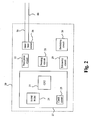
- Fig 2 is block diagram of the electronic circuitry and components of the implantable medical device in accordance with the present invention.
- the pacemaker 20 comprises a stimulation control circuit 27 for controlling the pacing and sensing functions of the device.
- the control circuit 27 controls, inter alia, pace pulse parameters such as output voltage and pulse duration.
- the control circuit 27 includes circuits well-known in the art, for example, a RAM/ROM unit (random-access and read-only memory) 24, a crystal clock 23, and a central processing unit (CPU) 25.
- the pacemaker further includes circuits well-known in the art, for example, a sensing circuit 21, and a pace pulse circuit 22.
- the pacemaker 20 includes a communication unit 29 adapted to communicate with an external programmer/control unit (not shown).
- the pacemaker 20 is connectable to pacemaker leads 6a, a right ventricular lead, and 6b, right atrium lead, respectively, for delivering signals between the pacemaker 20 and tissue of the heart.
- the leads 6a, and 6b may be unipolar or bipolar, and may include any of the passive or active fixation means known in the art for fixation of the lead to the cardiac tissue.
- the lead distal tip (not shown) may include a tined tip or a fixation helix.
- the leads 6a and 6b comprises one or more electrodes such tip electrodes, ring electrodes, coil electrodes, arranged to, inter alia, transmit pacing pulses for causing depolarization of cardiac tissue adjacent to the electrode(-s) generated by a pace pulse circuit 22 under influence of the control circuit 27.
- the coupling of conductors of the leads 6a and 6b and internal components of the pacemaker 20 may be by means of an interface circuit 28 which functions, in a multiplexer-like manner, to selectively and dynamically establish necessary connections between various conductors of the leads 6a and 6b and the components of the pacemaker as familiar to the man skilled within the art.
- the CPU 25 functions to control the timed operation of the pace pulse circuit 22 and the sensing circuit 21 under control of programming stored in the RAM/ROM unit 24.
- the clock circuit 23, for example, a crystal controlled oscillator provides main timing clock signals to the pace pulse circuit 22.
- the lines over which such signals are transmitted to the various times circuits are omitted in Fig. 2 .
- the components of the pacemaker 20 are powered by a battery (not shown) in accordance with common practice within the art.
- the sensing circuit 21 which is of conventional design, is adapted to receive electrical cardiac signals from the leads 6a and 6b and to process such signals to detect the occurrence of specific cardiac events, for example, atrial contractions (P-waves) and ventricular contractions (R-waves).
- the sensing circuit may provide event-indicating signals, e.g. signals indicating the detected event including atrial contractions (P-waves) and ventricular contractions (R-waves), which may be used by the CPU 25 to control the synchronous stimulating operations of the pacemaker 20 in accordance with common practice within the art.
- the pacemaker 20 further comprises a switching circuit 26 adapted to switch between operation modes including a DDI-II mode, a DDI mode and a DDD mode.
- operation modes including a DDI-II mode, a DDI mode and a DDD mode.
- the letters defining the features of the operation modes are, for the person familiar with the state of the art, the well-known NBG code.
- the DDI-II mode is an operation mode with an atrial inhibited pacing and a DDI-II mode ventricular pacing set at percentage of the atrial rate, at a predetermined rate which is lower than the base rate.
- Intrinsic atrial activity during the alert period will inhibit the output pulse and reset the pacemaker timing to the beginning of the refractory period.
- the ventricular pacing thus functions as a back-up pacing in case the atrio-ventricular conduction is temporary blocked.
- the ventricular timer function will operate at an interval which is extended to a percentage of the atrial timer.
- the atrial rate may be set to 60 Bpm, and the atrial timer is thus set to 1000 ms.
- the ventricular timer may be set to 140 % of the atrial, the ventricular timer is thus set to 1400 ms or 42 Bpm.
- the DDI mode refers to dual-chamber, non-tracking pacing, with sensing in both chambers. Pacing and sensing occur in both the atrium and ventricle with inhibited response.
- the synchronized atrial and ventricular pacing, i.e. sensing and stimulation can be effected in both in atrium and ventricle, in accordance with common practice within the art.
- An A-V interval timer can be reset by an expired atrial escape interval (atrial pacing is delivered if no inhibition has occurred) and a sensed spontaneous ventricle event outside the A-V interval. In the absence of ventricular activity, a ventricular output pulse will be provided at the end of the programmed rate (V-V) interval.
- AV sequential pacing at the programmed rate is provided in the absence of intrinsic activity. Additionally, intrinsic ventricular activity occurring during the ventricular alter period of the atrial escape interval or AV delay will thus inhibit the pacemaker and reset the timing
- the DDD mode refers to dual-chamber pacing with atrial tracking, i.e. pacing and sensing in both atrium and ventricle with dual response (inhibited or triggered) to sensing.
- both chambers are paced at a programmed base rate and AV delay.
- Atrial and ventricular events are sensed and stimulation can be delivered in both atrium and ventricle in accordance with common practice within the art.
- An A-V interval timer can be reset by a sensed atrial event, an expired atrial escape interval and a sensed spontaneous ventricle event outside the A-V interval.
- an atrial pulse is delivered at the end of the atrial alert interval and the timing cycle for the AV delay beings.
- rate acceleration does not occur if an intrinsic ventricular event is sensed during the AV/PV delay, although ventricular output is inhibited. If no ventricular event is sensed in AV/PV delay, it times out, a ventricular pulse is delivered, and the timing cycle for the atrial escape interval begins.
- Intrinsic ventricular activity sensed during the ventricular alert period will inhibit both atrial and ventricular output pulses and recycle the timing cycles on both channels to the beginning of the atrial alert interval.
- the pacemaker 20 may comprise other components and circuits, for example, activity sensors in addition to the components and circuits described above.
- a high-level flow chart illustrating an embodiment for selectively providing cardiac pacing to a heart of a patient according to the present invention will be discussed.
- the pacemaker is operated in the DDI-II mode. It is continuously checked, in step 31, whether atrio-ventricular block is detected and if a block is detected the procedure proceeds to step 32.
- a check whether at least one first switching criterion is satisfied or whether at least a first switching event has been detected or occurred is performed.
- the at least one first switching criterion is that no intrinsic ventricular event has been detected during a period of at least two consecutive cardiac cycles, i.e. the ventricle has been paced with the predetermined DDI-II mode ventricular rate during two consecutive cycles. If the at least one first criterion is not satisfied, i.e. the atrio-ventricular conduction is restored within the period of time defined by the first switching criterion, the procedure returns to step 30.
- the procedure proceeds to step 33 where a mode switch from the DDI-II mode to the DDI mode is executed.
- the ventricular pacing rate of the DDI-II mode is used in the DDI mode as an initial ventricular pacing rate.
- a check is regularly performed whether the atrio-ventricular conduction has been restored, i.e. whether an intrinsic ventricular event is sensed in the next cardiac cycle, for example, in each cycle. It may also be checked whether the restored conduction is temporary or not. That is, if the conduction is restored for a period of time being longer than a predetermined period. For example, if at least a predetermined number of successive or consecutive intrinsic ventricular events are detected, i.e. a predetermined number of consecutive inhibitions. If the atrio-ventricular conduction has been restored (and is determined not to be only temporary), the procedure returns to step 30, i.e. the operation mode switches back to the DDI-II mode.
- the procedure proceeds to step 35 where it is checked whether at least one second switching criterion is satisfied or whether at least a first switching event has been detected or occurred is performed.
- the at least one second switching criterion is that a number of consecutive ventricular pacing pulses have been delivered. If yes, the procedure proceeds to step 36 where the operation mode is switched from the DDI mode to the DDD mode. On the other hand, if no, the procedure returns to step 33 and hence the operation is maintained in the DDI mode.
- the ventricular rate is adapted to regularly search for R-waves.
- a searching period is, at step 52, initiated in which a present ventricular pacing interval is prolonged during a period of time having a length of a predetermined number of cycles. For example, after a predetermined period of time, the ventricular pacing interval is prolonged, for a predetermined number of cycles, e.g.
- the ventricular interval may be set to 140 % of the present ventricular interval
- the search period may have a length of 5 cycles
- the search may be performed at intervals of 8000 ms.
- the at least one re-initiation criterion for the DDI-II mode may be that atrio-ventricular conduction is restored for a period being longer than a predetermined period of time or that a predetermined number of consecutive intrinsic ventricular events have been detected, i.e. the a predetermined number of consecutive inhibitions have occurred.
- the reinitiating criterion in the DDD mode is that atrio-ventricular conduction is restored for a period having a duration of a predetermined number of cardiac cycles, i.e. the intrinsic ventricular events are detected or sensed during a predetermined number of consecutive cycles.
- the control circuit is adapted to, when the device operates in the DDD mode, regularly search for intrinsic ventricular activity.
- Fig. 4 a high-level flow chart illustrating a further embodiment for selectively providing cardiac pacing to a heart of a patient according to the present invention will be discussed.
- the pacemaker is operated in the DDI-II mode. It is continuously checked, i.e. in each cycle, in step 41, whether atrio-ventricular block is detected and if a block is detected, i.e. a ventricular pace is delivered when the ventricular DDI-II mode interval has timed out (the prolonged initial interval set to a predetermined percentage of the base rate, for example, 140 %). If yes, the procedure proceeds to step 42.
- the ventricular DDI-II mode interval is adapted according to predetermined rules depending on at least one preceding ventricular event. In one embodiment, it is shortened with a predetermined percentage w % at each paced ventricular event. In one embodiment, the predetermined percentage is 10 %.
- the ventricular pacing interval is prolonged a predetermined percentage w/2 % for each intrinsic event and in another embodiment the interval is prolonged w/2 % for each two consecutive intrinsic ventricular events.
- the maximum length is the initial length of the interval, i.e. prolonged initial interval set to a predetermined percentage of the base rate, for example, 140 %. Subsequently, the procedure returns to step 40.
- step 43 i.e. the ventricular pacing interval is equal to the atrial interval
- the procedure proceeds to step 45 where a mode switch is executed and the operation mode is switched from the DDI-II mode to the DDI mode.
- a check is regularly performed whether the atrio-ventricular conduction has been restored, i.e. whether an intrinsic ventricular event is sensed in the next cardiac cycle, for example, in each cycle. It may also be checked whether the restored conduction is temporary or not. That is, if the conduction is restored for a period of time being longer than a predetermined period. For example, at least a predetermined number of successive or consecutive intrinsic ventricular events are detected, i.e. a predetermined number of consecutive inhibitions. If the atrio-ventricular conduction has been restored (and is determined not to be only temporary), the procedure returns to step 40, i.e. the operation mode switches back to the DDI-II mode from the DDI mode.
- the procedure proceeds to step 47 where it is checked whether at least one second switching criterion is satisfied or whether at least a first switching event has been detected or occurred is performed.
- the at least one second switching criterion is that a number of consecutive ventricular pacing pulses have been delivered. If yes, the procedure proceeds to step 48 where the operation mode is switched from the DDI mode to the DDD mode. On the other hand, if no, the procedure returns to step 45 and hence the operation is maintained in the DDI mode.
- the ventricular rate is adapted to regularly search for R-waves.
- a searching period is, at step 52, initiated in which a present ventricular pacing interval is prolonged during a period of time having a length of a predetermined number of cycles. For example, after a predetermined period of time, the ventricular pacing interval is prolonged, for a predetermined number of cycles, e.g.
- the ventricular interval may be set to 140 % of the present ventricular interval
- the search period may have a length of 5 cycles
- the search may be performed at intervals of 8000 ms.
- the at least one re-initiation criterion for the DDI-II mode may be that atrio-ventricular conduction is restored for a period being longer than a predetermined period of time or that a predetermined number of consecutive intrinsic ventricular events have been detected, i.e. the a predetermined number of consecutive inhibitions have occurred.
- the reinitiating criterion in the DDD mode is that atrio-ventricular conduction is restored for a period having a duration of a predetermined number of cardiac cycles, i.e. the intrinsic ventricular events are detected or sensed during a predetermined number of consecutive cycles.
- the control circuit is adapted to, when the device operates in the DDD mode, regularly search for intrinsic ventricular activity.
- the DDI-II mode is an operation mode with an atrial inhibited pacing and a DDI-II mode ventricular pacing rate which is set at percentage of the atrial rate, i.e. at a predetermined rate which is lower than the base rate.
- the ventricular pacing thus functions as a back-up pacing.
- the ventricular timer function will operate at an interval which is extended to a percentage of the atrial timer.
- the atrial rate may be set to 60 Bpm, and the atrial timer is thus set to 1000 ms.
- the ventricular timer may be set to 140 % of the atrial and the ventricular timer is thus set to 1400 ms or 42 Bpm.
- the pacemaker 20 is operated in the DDI-II mode.
- a paced atrial event A1 triggers an atrial refractory interval and the intrinsic ventricular event R1 triggers a ventricular refractory period and a ventricular DDI-II mode interval VI1, which is extended in comparison to the base interval.
- the atrial-ventricular conduction functions.
- the ventricular DDI-II mode interval is set to 140 % of the base interval.
- the paced atrial event A2 triggers an atrial refractory interval.
- An intrinsic ventricular event R2 is detected within the ventricular DDI-II mode interval VI1, hence resetting the ventricular DDI-II mode interval VI1 and initiating a new ventricular DDI-II mode interval VI2.
- the ventricular interval is maintained at the initial length since the initial length was used as timing interval. If it had been shorter than the initial length, due to the delivery of ventricular pacing, the ventricular interval had been prolonged w/2 %, for example, 5 %.
- a paced atrial event A3 triggers an atrial refractory interval. In this case, the ventricular DDI-II mode interval VI2 expires without the detection of an intrinsic ventricular event or R wave.
- a stimulation pulse for evoking a stimulation pulse is delivered evoking a ventricular event, which is indicated in Fig. 6 with V1.
- the ventricular interval is also shortened with w %, for example 10 %, for each paced ventricular event according to this embodiment. Thereby, a gradual increase of the DDI-II mode ventricular rate can be achieved and an abrupt switch from the DDI-II mode to the DDI mode can thus be avoided.
- the paced ventricular event V1 triggers a ventricular refractory interval and a new ventricular DDI-II mode interval VI3.
- a paced atrial event A4 triggers an atrial refractory interval.
- the ventricular DDI-II mode interval VI3 expires without the detection of an intrinsic ventricular event.
- a stimulation pulse for evoking a ventricular event is delivered, which event is indicated in Fig. 6 with V2.
- the ventricular interval is again shortened with w %.
- the mode switch from the DDI-II mode to the DDI mode will be executed if the ventricular interval is equal to the atrial interval.
- the mode switch from the DDI-II mode to the DDD mode will be executed at the occurrence of two consecutive paced ventricular events.
- FIG. 7 an example of the operation in the DDI mode according to the present invention will be discussed.
- the DDI mode is an operation mode with a synchronized atrial and ventricular pacing, i.e. sensing and stimulation can be effected in both in atrium and ventricle, in accordance with common practice within the art.
- An A-V interval timer can be reset by an expired atrial escape interval (atrial pacing is delivered if no inhibition has occurred) and a sensed spontaneous ventricle event outside the A-V interval.
- a paced atrial event A5 triggers an atrial refractory interval and an AV interval.
- the ventricular DDI mode interval VI4 expires without the detection of an intrinsic ventricular event. Synchronized with the point of time at which the ventricular DDI mode interval expires, a stimulation pulse for evoking a ventricular event is delivered resulting in a ventricular event, which is indicated in Fig. 7 with V3.
- the paced ventricular event V3 triggers a ventricular refractory interval and a new ventricular DDI mode interval VI5.
- the operational mode is maintained in the DDI mode since the at least one second switching criterion is not satisfied, which in this embodiment is that a predetermined number of consecutive ventricaul pacing pulses have been delivered.
- a mode switch from the DDI mode to the DDD mode is performed if the pacemaker has been operated in the DDI mode a predetermined period of time without a restoration of the atrio-ventricular conduction has occurred.
- a paced atrial event A6 triggers an atrial refractory interval and an AV interval.
- An intrinsic ventricular event R3 is detected during the ventricular DDI mode interval VI5, which resets the DDI mode interval VI5 and initiates a new interval VI6.
- a paced atrial event A7 triggers an atrial refractory interval and an AV interval.
- An intrinsic ventricular event R4 is detected during the ventricular DDI mode interval VI6, which resets the DDI mode interval VI6 and initiates a new interval VI7.
- a paced atrial event A8 triggers an atrial refractory interval and an AV interval.
- the ventricular DDI mode interval VI7 expires without the detection of an intrinsic ventricular event. Synchronized with the point of time at which the ventricular DDI mode interval expires, a stimulation pulse for evoking a ventricular event is delivered, which is indicated in Fig. 7 with V4.
- a mode switch from operation in the DDI mode to operation in the DDD mode will be discussed.
- atrial and ventricular events are sensed and stimulation can be delivered in both atrium and ventricle in accordance with common practice within the art.
- An A-V interval timer can be reset by a sensed atrial event, an expired atrial escape interval and a sensed spontaneous ventricle event outside the A-V interval.
- a paced atrial event A9 triggers an atrial refractory interval and an AV interval.
- a ventricular DDI mode interval VI10 expires without the detection of an intrinsic ventricular event. Synchronized with the point of time at which the ventricular DDI mode interval expires, a stimulation pulse for evoking a ventricular event is delivered, which is indicated in Fig. 8 with V5.
- the paced ventricular event V5 triggers a ventricular refractory interval and a new ventricular DDD mode interval VI11.
- a paced atrial event A10 triggers an atrial refractory interval and an AV interval.
- a ventricular DDD mode interval VI11 expires without the detection of an intrinsic ventricular event.
- a stimulation pulse for evoking a ventricular event is delivered, which is indicated in Fig. 8 with V6.
- the paced ventricular event V6 triggers a ventricular refractory interval and a new ventricular DDD mode interval VI12. Further, two consecutive ventricular pacing pulses have been delivered, which, in this embodiment, is the at least one second switching criterion.
- the operation mode is switched from the DDI mode to the DDD mode. The operation thus continues in the DDD mode and a paced atrial event A11 triggers an atrial refractory interval and an AV interval.
- a ventricular DDD mode interval VI12 expires without the detection of an intrinsic ventricular event.
- a stimulation pulse for evoking a ventricular event is delivered, which is indicated in Fig. 8 with V7.
- the paced ventricular event V7 triggers a ventricular refractory interval and a new ventricular DDD mode interval VI13.
- a paced atrial event A12 triggers an atrial refractory interval and an AV interval.
- the ventricular timer returns to the prolonged interval used in the DDD mode for a predetermined number of cycles at regular intervals in order to search for intrinsic events, i.e. R waves. This is illustrated in Fig. 8 by the prolonged ventricular DDD mode interval VI13.
- a stimulation pulse for evoking a ventricular event is delivered, which is indicated in Fig. 8 with V8.
- the paced ventricular event V8 triggers a ventricular refractory interval and a new ventricular DDD mode interval VI14, which also is prolonged (not shown in Fig. 8 ).
- the monitoring period has a length of two cycles but, as the skilled person realizes, may be arbitrary, for example, 3, 4 or 5 cycles.
- the ventricular timer will return to the regular DDD ventricular pacing rate from the prolonged ventricular rate after two cycles.
- the re-initiating criterion i.e. the criterion triggering a mode switch back to the DDI-II mode from the DDD mode, is that a predetermined number of consecutive intrinsic ventricular events have been detected, for example, four or five.
- the DDI-II mode ventricular pacing rate, which is lower than the base rate of the device, may be increased during a predetermined period of time. If the predetermined period of time, e.g. five cardiac cycles, expires without paced ventricular events, the ventricular pacing rate is adjusted back to the initial rate.
Landscapes
- Health & Medical Sciences (AREA)
- Cardiology (AREA)
- Heart & Thoracic Surgery (AREA)
- Life Sciences & Earth Sciences (AREA)
- Biophysics (AREA)
- Physiology (AREA)
- Engineering & Computer Science (AREA)
- Biomedical Technology (AREA)
- Nuclear Medicine, Radiotherapy & Molecular Imaging (AREA)
- Radiology & Medical Imaging (AREA)
- Animal Behavior & Ethology (AREA)
- General Health & Medical Sciences (AREA)
- Public Health (AREA)
- Veterinary Medicine (AREA)
- Electrotherapy Devices (AREA)
Claims (7)
- Implantierbares Medizinprodukt (IMP) (2, 20), das so ausgelegt ist, dass es gezielt ein Herz (8) eines Patienten stimuliert, umfassend:eine mit Herzleitungen (6a, 6b) verbindbare Stimulationsimpulsschaltung (22), die so ausgelegt ist, dass sie Herzstimulationsimpulse über die Herzleitungen (6a, 6b) an Herzgewebe abgibt;eine Überwachungsschaltung (21), die so ausgelegt ist, dass sie Vorhof- und/oder Herzkammerereignisse überwacht, wobei die atrioventrikuläre Überleitung festgestellt werden kann;eine Umschalt-Schaltung (26), die so ausgelegt ist, dass sie zwischen Betriebsarten des implantierbaren Medizinprodukts (2, 20) einschließlich eines DDI-II-Modus, eines DDI-Modus und eines DDD-Modus wechselt, wobei es sich bei dem DDI-II-Modus um eine Betriebsart mit einer inhibierten Vorhofstimulation handelt und eine Herzkammerstimulationsfrequenz im DDI-II-Modus niedriger ist als eine vorher festgelegte Grundfrequenz der Stimulationsimpulsschaltung (22), wobei es sich bei der Grundfrequenz um die Frequenz handelt, bei der die Stimulationsimpulsschaltung (22) Herzstimulationsimpulse bei Nichtvorliegen von Eigenaktivität erzeugt;eine Steuerschaltung (27), die so ausgelegt ist, dass sie:das Produkt während Zeiträumen mit atrioventrikulärenÜberleitungsbedingungen, bei denen es sich um Zeiträume mit aufeinanderfolgenden intrinsischen Herzkammerereignissen handelt, die durch höchstens eine vorher festgelegte Anzahl stimulierter Herzkammerereignisse unterbrochen werden, in dem DDI-II-Modus betreibt;
die Umschalt-Schaltung (26) so steuert, dass sie von demDDI-II-Modus in den DDI-Modus wechselt, wenn in der atrioventrikulären Überleitung ein Block erkannt wird und mindestens ein erstes Umschaltkriterium erfüllt ist, wobei das mindestens eine erste Umschaltkriterium aus Folgendem ausgewählt ist:während einem vorher festgelegten Zeitraum mit der Dauer von mindestens zwei Herzzyklen ist keine atrioventrikuläre Überleitung festgestellt worden; undein Herzkammerstimulationsintervall entspricht mindestens einem Vorhofstimulationsintervall; unddie Umschalt-Schaltung (26) so steuert, dass sie von dem DDI-Modus in den DDD-Modus wechselt, wenn in der atrioventrikulären Überleitung ein Block erkannt wird und mindestens ein zweites Umschaltkriterium erfüllt ist, wobei das mindestens eine zweite Umschaltkriterium aus Folgendem ausgewählt ist:Herzkammerstimulationsimpulse sind über einen Zeitraum mit einer vorher festgelegten Zeitdauer abgegeben worden; undmindestens zwei aufeinanderfolgende Herzkammerstimulationsimpulse sind abgegeben worden; undwobei die Steuerschaltung (27) so ausgelegt ist, dass sie, wenn das implantierbare Medizinprodukt (2, 20) in dem DDI-Modus betrieben wird, die Umschalt-Schaltung (26) so steuert, dass sie beim Erfüllen von mindestens einem Wiederaufnahmekriterium zurück in den DDI-II-Modus wechselt, wobei das mindestens eine Wiederaufnahmekriterium aus Folgendem ausgewählt ist:die atrioventrikuläre Überleitung ist für einen Zeitraum, der länger ist als ein vorher festgelegter Zeitraum, wiederhergestellt;eine vorher festgelegte Anzahl von aufeinanderfolgenden intrinsischen Herzkammerereignissen ist festgestellt worden; unddie atrioventrikuläre Überleitung ist für einen Zeitraum mit der Dauer einer vorher festgelegten Anzahl von Herzzyklen wiederhergestellt. - Implantierbares Medizinprodukt nach Anspruch 1, wobei die Steuerschaltung (27) so ausgelegt ist, dass sie, wenn das implantierbare Medizinprodukt (2, 20) in dem DDI-II-Modus betrieben wird:die Stimulationsimpulsschaltung (22) bei jedem intrinsischen oder stimulierten Herzkammerereignis so steuert, dass ein Herzkammerstimulationsintervall gemäß vorher festgelegten Regeln in Abhängigkeit von mindestens einem vorhergehenden Herzkammerereignis angepasst wird.
- Implantierbares Medizinprodukt nach Anspruch 2, wobei die Steuerschaltung (27) so ausgelegt ist, dass sie:die Stimulationsimpulsschaltung (22) bei jedem stimulierten Herzkammerereignis so steuert, dass ein gegenwärtiges Herzkammerstimulationsintervall mit einem ersten vorher festgelegten Prozentsatz gemäß den vorher festgelegten Regeln verkürzt wird; undbeim Wahrnehmen von mindestens zwei aufeinanderfolgenden intrinsischen Herzkammerereignissen die Stimulationsimpulsschaltung (22) so steuert, dass das gegenwärtige Herzkammerstimulationsintervall mit einem zweiten vorher festgelegten Prozentsatz gemäß den vorher festgelegten Regeln verlängert wird.
- Implantierbares Medizinprodukt nach Anspruch 2, wobei die Steuerschaltung (27) so ausgelegt ist, dass sie:die Stimulationsimpulsschaltung (22) bei jedem stimulierten Herzkammerereignis so steuert, dass ein gegenwärtiges Herzkammerstimulationsintervall mit einem ersten vorher festgelegten Prozentsatz bezogen auf eine Herzkammerstimulations-Anfangsfrequenz gemäß den vorher festgelegten Regeln verkürzt wird; undbeim Wahrnehmen von mindestens zwei aufeinanderfolgenden intrinsischen Herzkammerereignissen die Stimulationsimpulsschaltung (22) so steuert, dass das gegenwärtige Herzkammerstimulationsintervall mit einem zweiten vorher festgelegten Prozentsatz bezogen auf die Herzkammerstimulations-Anfangsfrequenz gemäß den vorher festgelegten Regeln verlängert wird; undwobei es sich bei der Herzkammerstimulations-Anfangsfrequenz um die Herzkammerstimulationsfrequenz im DDI-II-Modus handelt.
- Implantierbares Medizinprodukt nach einem der vorhergehenden Ansprüche, wobei die Steuerschaltung (27) so ausgelegt ist, dass sie, wenn das implantierbare Medizinprodukt (2, 20) in dem DDD-Modus arbeitet, regelmäßig nach ventrikulärer Eigenaktivität sucht.
- Implantierbares Medizinprodukt nach Anspruch 5, wobei die Steuerschaltung (27) so ausgelegt ist, dass sie in regelmäßigen Abständen die Stimulationsimpulsschaltung (22) so steuert, dass während eines Zeitraums mit einer Länge von einer vorher festgelegten Anzahl von Zyklen ein gegenwärtiges Herzkammerstimulationsintervall verlängert wird.
- Implantierbares Medizinprodukt nach Anspruch 6, wobei die Steuerschaltung (27) so ausgelegt ist, dass sie die Stimulationsimpulsschaltung (22) so steuert, dass ein gegenwärtiges Herzkammerstimulationsintervall während des Zeitraums auf das Herzkammerstimulationsintervall im DDI-II-Modus verlängert wird.
Applications Claiming Priority (1)
| Application Number | Priority Date | Filing Date | Title |
|---|---|---|---|
| PCT/SE2007/000587 WO2008153453A1 (en) | 2007-06-15 | 2007-06-15 | Dual chamber pacemaker |
Publications (3)
| Publication Number | Publication Date |
|---|---|
| EP2158002A1 EP2158002A1 (de) | 2010-03-03 |
| EP2158002A4 EP2158002A4 (de) | 2013-08-21 |
| EP2158002B1 true EP2158002B1 (de) | 2014-05-14 |
Family
ID=40129926
Family Applications (1)
| Application Number | Title | Priority Date | Filing Date |
|---|---|---|---|
| EP07748250.3A Not-in-force EP2158002B1 (de) | 2007-06-15 | 2007-06-15 | Schrittmacher mit zwei kammern |
Country Status (3)
| Country | Link |
|---|---|
| US (1) | US8180449B2 (de) |
| EP (1) | EP2158002B1 (de) |
| WO (1) | WO2008153453A1 (de) |
Families Citing this family (8)
| Publication number | Priority date | Publication date | Assignee | Title |
|---|---|---|---|---|
| CN111432875B (zh) | 2017-12-01 | 2024-04-30 | 心脏起搏器股份公司 | 从心室植入式无引线心脏起搏器检测心房收缩定时基准并确定心脏间隔的方法和系统 |
| US11052258B2 (en) | 2017-12-01 | 2021-07-06 | Cardiac Pacemakers, Inc. | Methods and systems for detecting atrial contraction timing fiducials within a search window from a ventricularly implanted leadless cardiac pacemaker |
| US11813463B2 (en) | 2017-12-01 | 2023-11-14 | Cardiac Pacemakers, Inc. | Leadless cardiac pacemaker with reversionary behavior |
| CN111417433B (zh) | 2017-12-01 | 2024-04-30 | 心脏起搏器股份公司 | 从心室植入的无引线心脏起搏器检测心室充盈期间心房收缩定时基准的方法和系统 |
| CN109589499B (zh) * | 2018-12-06 | 2020-09-15 | 创领心律管理医疗器械(上海)有限公司 | 心脏起搏系统 |
| US11446505B2 (en) | 2019-05-31 | 2022-09-20 | Cardiac Pacemakers, Inc. | His-bundle pacing for atrioventricular block |
| EP4142865A1 (de) * | 2020-04-27 | 2023-03-08 | BIOTRONIK SE & Co. KG | Therapie für bluthochdruck |
| CN116549854B (zh) * | 2023-04-20 | 2023-11-17 | 丹源医学科技(杭州)有限公司 | 一种最小化心室起搏的双腔起搏装置 |
Family Cites Families (7)
| Publication number | Priority date | Publication date | Assignee | Title |
|---|---|---|---|---|
| US5318594A (en) * | 1990-11-30 | 1994-06-07 | Ela Medical | DDD type cardiac pacemaker having automatic operating mode switching |
| WO1999010044A1 (en) | 1997-08-22 | 1999-03-04 | Henning Rud Andersen | Dual chamber pacemaker that automatically changes mode, when prolonged vv-interval is detected |
| US7254441B2 (en) * | 2000-12-21 | 2007-08-07 | Medtronic, Inc. | Fully inhibited dual chamber pacing mode |
| US7130683B2 (en) * | 2000-12-21 | 2006-10-31 | Medtronic, Inc. | Preferred ADI/R: a permanent pacing mode to eliminate ventricular pacing while maintaining back support |
| US6772005B2 (en) * | 2000-12-21 | 2004-08-03 | Medtronic, Inc. | Preferred ADI/R: a permanent pacing mode to eliminate ventricular pacing while maintaining backup support |
| FR2837394B1 (fr) * | 2002-03-22 | 2004-06-11 | Ela Medical Sa | Dispositif medical implantable actif tel que stimulateur cardiaque, defribillateur et/ou cardiovecteur, a commutation de mode ddd/aai perfectionnee |
| US7257442B2 (en) * | 2004-05-26 | 2007-08-14 | Cardiac Pacemakers, Inc. | Mode switching algorithm for AV block |
-
2007
- 2007-06-15 EP EP07748250.3A patent/EP2158002B1/de not_active Not-in-force
- 2007-06-15 US US12/663,327 patent/US8180449B2/en not_active Expired - Fee Related
- 2007-06-15 WO PCT/SE2007/000587 patent/WO2008153453A1/en not_active Ceased
Also Published As
| Publication number | Publication date |
|---|---|
| US8180449B2 (en) | 2012-05-15 |
| WO2008153453A1 (en) | 2008-12-18 |
| EP2158002A4 (de) | 2013-08-21 |
| US20100174333A1 (en) | 2010-07-08 |
| EP2158002A1 (de) | 2010-03-03 |
Similar Documents
| Publication | Publication Date | Title |
|---|---|---|
| EP3285858B1 (de) | System zur doppelkammerschrittsteuerung | |
| EP1549393B1 (de) | Herzschrittmacher mit Stimulation vom Typ ADI-R | |
| US6792307B1 (en) | Implantable cardiac stimulation system and method for measuring atrioventricular conduction and adjusting atrioventricular hysteresis | |
| US6122546A (en) | Pacemaker and method of operating same that provides functional atrial cardiac pacing with ventricular support | |
| US6615082B1 (en) | Method and device for optimally altering stimulation energy to maintain capture of cardiac tissue | |
| EP0753325B1 (de) | Verbesserte Reaktion bei der oberen Grenzfrequenz in einem implantierbaren Herzschrittmacher basierend auf atrial gesteuerter Stimulation | |
| EP2158002B1 (de) | Schrittmacher mit zwei kammern | |
| EP0559193B1 (de) | Implantierbarer Herzschrittmacher mit Hysteresefunktion bei Zweikammerbetriebsarten | |
| EP1901801B1 (de) | System und verfahren für ventrikuläres pacing mit av-intervall-modulation | |
| US7881793B2 (en) | System and method for ventricular pacing with progressive conduction check interval | |
| US5086774A (en) | System and method for automatically compensating for latency conduction time in a programmable pacemaker | |
| EP0872260A2 (de) | Implantierbarer Herzschrittmacher | |
| US7826898B2 (en) | Implantable cardiac device providing intrinsic conduction search with premature atrial contraction protection and method | |
| US20090005828A1 (en) | Implantable medical device for identifying and managing intrinsic reentrant tachycardia | |
| EP1878465B1 (de) | Herzschrittmacher | |
| JP2005518256A (ja) | 適応的な不整脈検出ウィンドウを有するペースメーカ | |
| US6456879B1 (en) | Method and device for optimally altering stimulation energy to maintain capture of cardiac tissue | |
| US7756570B1 (en) | Methods and arrangements for reducing oversensing and/or providing diagnostic information in implantable medical devices | |
| EP1987857B1 (de) | Implantierbare medizinische Vorrichtung zur biventrikulären Stimulation | |
| WO2006104845A1 (en) | System and method for ventricular pacing with progressive conduction check interval | |
| US8131366B2 (en) | Biventricular heart stimulator and method of controlling a biventricular heart stimulator | |
| EP1885440B1 (de) | System für kammer-pacing mit progressivem überleitungsprüfungsintervall |
Legal Events
| Date | Code | Title | Description |
|---|---|---|---|
| PUAI | Public reference made under article 153(3) epc to a published international application that has entered the european phase |
Free format text: ORIGINAL CODE: 0009012 |
|
| 17P | Request for examination filed |
Effective date: 20100115 |
|
| AK | Designated contracting states |
Kind code of ref document: A1 Designated state(s): AT BE BG CH CY CZ DE DK EE ES FI FR GB GR HU IE IS IT LI LT LU LV MC MT NL PL PT RO SE SI SK TR |
|
| AX | Request for extension of the european patent |
Extension state: AL BA HR MK RS |
|
| DAX | Request for extension of the european patent (deleted) | ||
| A4 | Supplementary search report drawn up and despatched |
Effective date: 20130719 |
|
| RIC1 | Information provided on ipc code assigned before grant |
Ipc: A61N 1/368 20060101AFI20130715BHEP |
|
| GRAP | Despatch of communication of intention to grant a patent |
Free format text: ORIGINAL CODE: EPIDOSNIGR1 |
|
| INTG | Intention to grant announced |
Effective date: 20131219 |
|
| GRAS | Grant fee paid |
Free format text: ORIGINAL CODE: EPIDOSNIGR3 |
|
| GRAA | (expected) grant |
Free format text: ORIGINAL CODE: 0009210 |
|
| AK | Designated contracting states |
Kind code of ref document: B1 Designated state(s): AT BE BG CH CY CZ DE DK EE ES FI FR GB GR HU IE IS IT LI LT LU LV MC MT NL PL PT RO SE SI SK TR |
|
| REG | Reference to a national code |
Ref country code: GB Ref legal event code: FG4D |
|
| REG | Reference to a national code |
Ref country code: CH Ref legal event code: NV Representative=s name: E. BLUM AND CO. AG PATENT- UND MARKENANWAELTE , CH |
|
| REG | Reference to a national code |
Ref country code: AT Ref legal event code: REF Ref document number: 667781 Country of ref document: AT Kind code of ref document: T Effective date: 20140615 |
|
| REG | Reference to a national code |
Ref country code: IE Ref legal event code: FG4D |
|
| REG | Reference to a national code |
Ref country code: DE Ref legal event code: R096 Ref document number: 602007036718 Country of ref document: DE Effective date: 20140626 |
|
| REG | Reference to a national code |
Ref country code: NL Ref legal event code: VDEP Effective date: 20140514 Ref country code: AT Ref legal event code: MK05 Ref document number: 667781 Country of ref document: AT Kind code of ref document: T Effective date: 20140514 |
|
| REG | Reference to a national code |
Ref country code: LT Ref legal event code: MG4D |
|
| PG25 | Lapsed in a contracting state [announced via postgrant information from national office to epo] |
Ref country code: GR Free format text: LAPSE BECAUSE OF FAILURE TO SUBMIT A TRANSLATION OF THE DESCRIPTION OR TO PAY THE FEE WITHIN THE PRESCRIBED TIME-LIMIT Effective date: 20140815 Ref country code: IS Free format text: LAPSE BECAUSE OF FAILURE TO SUBMIT A TRANSLATION OF THE DESCRIPTION OR TO PAY THE FEE WITHIN THE PRESCRIBED TIME-LIMIT Effective date: 20140914 Ref country code: LT Free format text: LAPSE BECAUSE OF FAILURE TO SUBMIT A TRANSLATION OF THE DESCRIPTION OR TO PAY THE FEE WITHIN THE PRESCRIBED TIME-LIMIT Effective date: 20140514 Ref country code: CY Free format text: LAPSE BECAUSE OF FAILURE TO SUBMIT A TRANSLATION OF THE DESCRIPTION OR TO PAY THE FEE WITHIN THE PRESCRIBED TIME-LIMIT Effective date: 20140514 Ref country code: FI Free format text: LAPSE BECAUSE OF FAILURE TO SUBMIT A TRANSLATION OF THE DESCRIPTION OR TO PAY THE FEE WITHIN THE PRESCRIBED TIME-LIMIT Effective date: 20140514 |
|
| PG25 | Lapsed in a contracting state [announced via postgrant information from national office to epo] |
Ref country code: LV Free format text: LAPSE BECAUSE OF FAILURE TO SUBMIT A TRANSLATION OF THE DESCRIPTION OR TO PAY THE FEE WITHIN THE PRESCRIBED TIME-LIMIT Effective date: 20140514 Ref country code: ES Free format text: LAPSE BECAUSE OF FAILURE TO SUBMIT A TRANSLATION OF THE DESCRIPTION OR TO PAY THE FEE WITHIN THE PRESCRIBED TIME-LIMIT Effective date: 20140514 Ref country code: SE Free format text: LAPSE BECAUSE OF FAILURE TO SUBMIT A TRANSLATION OF THE DESCRIPTION OR TO PAY THE FEE WITHIN THE PRESCRIBED TIME-LIMIT Effective date: 20140514 Ref country code: PL Free format text: LAPSE BECAUSE OF FAILURE TO SUBMIT A TRANSLATION OF THE DESCRIPTION OR TO PAY THE FEE WITHIN THE PRESCRIBED TIME-LIMIT Effective date: 20140514 Ref country code: AT Free format text: LAPSE BECAUSE OF FAILURE TO SUBMIT A TRANSLATION OF THE DESCRIPTION OR TO PAY THE FEE WITHIN THE PRESCRIBED TIME-LIMIT Effective date: 20140514 |
|
| PG25 | Lapsed in a contracting state [announced via postgrant information from national office to epo] |
Ref country code: PT Free format text: LAPSE BECAUSE OF FAILURE TO SUBMIT A TRANSLATION OF THE DESCRIPTION OR TO PAY THE FEE WITHIN THE PRESCRIBED TIME-LIMIT Effective date: 20140915 |
|
| PG25 | Lapsed in a contracting state [announced via postgrant information from national office to epo] |
Ref country code: RO Free format text: LAPSE BECAUSE OF FAILURE TO SUBMIT A TRANSLATION OF THE DESCRIPTION OR TO PAY THE FEE WITHIN THE PRESCRIBED TIME-LIMIT Effective date: 20140514 Ref country code: SK Free format text: LAPSE BECAUSE OF FAILURE TO SUBMIT A TRANSLATION OF THE DESCRIPTION OR TO PAY THE FEE WITHIN THE PRESCRIBED TIME-LIMIT Effective date: 20140514 Ref country code: CZ Free format text: LAPSE BECAUSE OF FAILURE TO SUBMIT A TRANSLATION OF THE DESCRIPTION OR TO PAY THE FEE WITHIN THE PRESCRIBED TIME-LIMIT Effective date: 20140514 Ref country code: EE Free format text: LAPSE BECAUSE OF FAILURE TO SUBMIT A TRANSLATION OF THE DESCRIPTION OR TO PAY THE FEE WITHIN THE PRESCRIBED TIME-LIMIT Effective date: 20140514 Ref country code: BE Free format text: LAPSE BECAUSE OF FAILURE TO SUBMIT A TRANSLATION OF THE DESCRIPTION OR TO PAY THE FEE WITHIN THE PRESCRIBED TIME-LIMIT Effective date: 20140514 Ref country code: DK Free format text: LAPSE BECAUSE OF FAILURE TO SUBMIT A TRANSLATION OF THE DESCRIPTION OR TO PAY THE FEE WITHIN THE PRESCRIBED TIME-LIMIT Effective date: 20140514 |
|
| REG | Reference to a national code |
Ref country code: DE Ref legal event code: R097 Ref document number: 602007036718 Country of ref document: DE |
|
| PG25 | Lapsed in a contracting state [announced via postgrant information from national office to epo] |
Ref country code: NL Free format text: LAPSE BECAUSE OF FAILURE TO SUBMIT A TRANSLATION OF THE DESCRIPTION OR TO PAY THE FEE WITHIN THE PRESCRIBED TIME-LIMIT Effective date: 20140514 |
|
| PLBE | No opposition filed within time limit |
Free format text: ORIGINAL CODE: 0009261 |
|
| STAA | Information on the status of an ep patent application or granted ep patent |
Free format text: STATUS: NO OPPOSITION FILED WITHIN TIME LIMIT |
|
| REG | Reference to a national code |
Ref country code: IE Ref legal event code: MM4A |
|
| 26N | No opposition filed |
Effective date: 20150217 |
|
| GBPC | Gb: european patent ceased through non-payment of renewal fee |
Effective date: 20140814 |
|
| PG25 | Lapsed in a contracting state [announced via postgrant information from national office to epo] |
Ref country code: IE Free format text: LAPSE BECAUSE OF NON-PAYMENT OF DUE FEES Effective date: 20140615 |
|
| REG | Reference to a national code |
Ref country code: DE Ref legal event code: R097 Ref document number: 602007036718 Country of ref document: DE Effective date: 20150217 |
|
| PG25 | Lapsed in a contracting state [announced via postgrant information from national office to epo] |
Ref country code: GB Free format text: LAPSE BECAUSE OF NON-PAYMENT OF DUE FEES Effective date: 20140814 Ref country code: SI Free format text: LAPSE BECAUSE OF FAILURE TO SUBMIT A TRANSLATION OF THE DESCRIPTION OR TO PAY THE FEE WITHIN THE PRESCRIBED TIME-LIMIT Effective date: 20140514 |
|
| PG25 | Lapsed in a contracting state [announced via postgrant information from national office to epo] |
Ref country code: MT Free format text: LAPSE BECAUSE OF FAILURE TO SUBMIT A TRANSLATION OF THE DESCRIPTION OR TO PAY THE FEE WITHIN THE PRESCRIBED TIME-LIMIT Effective date: 20140514 |
|
| PG25 | Lapsed in a contracting state [announced via postgrant information from national office to epo] |
Ref country code: MC Free format text: LAPSE BECAUSE OF FAILURE TO SUBMIT A TRANSLATION OF THE DESCRIPTION OR TO PAY THE FEE WITHIN THE PRESCRIBED TIME-LIMIT Effective date: 20140514 |
|
| PG25 | Lapsed in a contracting state [announced via postgrant information from national office to epo] |
Ref country code: BG Free format text: LAPSE BECAUSE OF FAILURE TO SUBMIT A TRANSLATION OF THE DESCRIPTION OR TO PAY THE FEE WITHIN THE PRESCRIBED TIME-LIMIT Effective date: 20140514 |
|
| REG | Reference to a national code |
Ref country code: FR Ref legal event code: PLFP Year of fee payment: 10 |
|
| PG25 | Lapsed in a contracting state [announced via postgrant information from national office to epo] |
Ref country code: TR Free format text: LAPSE BECAUSE OF FAILURE TO SUBMIT A TRANSLATION OF THE DESCRIPTION OR TO PAY THE FEE WITHIN THE PRESCRIBED TIME-LIMIT Effective date: 20140514 Ref country code: LU Free format text: LAPSE BECAUSE OF NON-PAYMENT OF DUE FEES Effective date: 20140615 Ref country code: HU Free format text: LAPSE BECAUSE OF FAILURE TO SUBMIT A TRANSLATION OF THE DESCRIPTION OR TO PAY THE FEE WITHIN THE PRESCRIBED TIME-LIMIT; INVALID AB INITIO Effective date: 20070615 |
|
| PGFP | Annual fee paid to national office [announced via postgrant information from national office to epo] |
Ref country code: CH Payment date: 20160627 Year of fee payment: 10 |
|
| PGFP | Annual fee paid to national office [announced via postgrant information from national office to epo] |
Ref country code: FR Payment date: 20160628 Year of fee payment: 10 |
|
| PGFP | Annual fee paid to national office [announced via postgrant information from national office to epo] |
Ref country code: IT Payment date: 20160627 Year of fee payment: 10 |
|
| REG | Reference to a national code |
Ref country code: CH Ref legal event code: PL |
|
| REG | Reference to a national code |
Ref country code: FR Ref legal event code: ST Effective date: 20180228 |
|
| PG25 | Lapsed in a contracting state [announced via postgrant information from national office to epo] |
Ref country code: LI Free format text: LAPSE BECAUSE OF NON-PAYMENT OF DUE FEES Effective date: 20170630 Ref country code: CH Free format text: LAPSE BECAUSE OF NON-PAYMENT OF DUE FEES Effective date: 20170630 |
|
| PG25 | Lapsed in a contracting state [announced via postgrant information from national office to epo] |
Ref country code: FR Free format text: LAPSE BECAUSE OF NON-PAYMENT OF DUE FEES Effective date: 20170630 Ref country code: IT Free format text: LAPSE BECAUSE OF NON-PAYMENT OF DUE FEES Effective date: 20170615 |
|
| PGFP | Annual fee paid to national office [announced via postgrant information from national office to epo] |
Ref country code: DE Payment date: 20200518 Year of fee payment: 14 |
|
| REG | Reference to a national code |
Ref country code: DE Ref legal event code: R119 Ref document number: 602007036718 Country of ref document: DE |
|
| PG25 | Lapsed in a contracting state [announced via postgrant information from national office to epo] |
Ref country code: DE Free format text: LAPSE BECAUSE OF NON-PAYMENT OF DUE FEES Effective date: 20220101 |
|
| P01 | Opt-out of the competence of the unified patent court (upc) registered |
Effective date: 20230602 |