EP2158029B1 - Prozessgasfilter und verfahren zur reinigung des filters - Google Patents
Prozessgasfilter und verfahren zur reinigung des filters Download PDFInfo
- Publication number
- EP2158029B1 EP2158029B1 EP07722697.5A EP07722697A EP2158029B1 EP 2158029 B1 EP2158029 B1 EP 2158029B1 EP 07722697 A EP07722697 A EP 07722697A EP 2158029 B1 EP2158029 B1 EP 2158029B1
- Authority
- EP
- European Patent Office
- Prior art keywords
- heater
- filter
- gas
- spray drying
- drying chamber
- Prior art date
- Legal status (The legal status is an assumption and is not a legal conclusion. Google has not performed a legal analysis and makes no representation as to the accuracy of the status listed.)
- Active
Links
Images

Classifications
-
- B—PERFORMING OPERATIONS; TRANSPORTING
- B01—PHYSICAL OR CHEMICAL PROCESSES OR APPARATUS IN GENERAL
- B01J—CHEMICAL OR PHYSICAL PROCESSES, e.g. CATALYSIS OR COLLOID CHEMISTRY; THEIR RELEVANT APPARATUS
- B01J2/00—Processes or devices for granulating materials, e.g. fertilisers in general; Rendering particulate materials free flowing in general, e.g. making them hydrophobic
- B01J2/02—Processes or devices for granulating materials, e.g. fertilisers in general; Rendering particulate materials free flowing in general, e.g. making them hydrophobic by dividing the liquid material into drops, e.g. by spraying, and solidifying the drops
- B01J2/04—Processes or devices for granulating materials, e.g. fertilisers in general; Rendering particulate materials free flowing in general, e.g. making them hydrophobic by dividing the liquid material into drops, e.g. by spraying, and solidifying the drops in a gaseous medium
-
- B—PERFORMING OPERATIONS; TRANSPORTING
- B01—PHYSICAL OR CHEMICAL PROCESSES OR APPARATUS IN GENERAL
- B01D—SEPARATION
- B01D1/00—Evaporating
- B01D1/16—Evaporating by spraying
- B01D1/18—Evaporating by spraying to obtain dry solids
-
- B—PERFORMING OPERATIONS; TRANSPORTING
- B01—PHYSICAL OR CHEMICAL PROCESSES OR APPARATUS IN GENERAL
- B01J—CHEMICAL OR PHYSICAL PROCESSES, e.g. CATALYSIS OR COLLOID CHEMISTRY; THEIR RELEVANT APPARATUS
- B01J2/00—Processes or devices for granulating materials, e.g. fertilisers in general; Rendering particulate materials free flowing in general, e.g. making them hydrophobic
- B01J2/02—Processes or devices for granulating materials, e.g. fertilisers in general; Rendering particulate materials free flowing in general, e.g. making them hydrophobic by dividing the liquid material into drops, e.g. by spraying, and solidifying the drops
-
- F—MECHANICAL ENGINEERING; LIGHTING; HEATING; WEAPONS; BLASTING
- F26—DRYING
- F26B—DRYING SOLID MATERIALS OR OBJECTS BY REMOVING LIQUID THEREFROM
- F26B21/00—Arrangements for supplying or controlling air or other gases for drying solid materials or objects
- F26B21/003—Air or gas filters
-
- F—MECHANICAL ENGINEERING; LIGHTING; HEATING; WEAPONS; BLASTING
- F26—DRYING
- F26B—DRYING SOLID MATERIALS OR OBJECTS BY REMOVING LIQUID THEREFROM
- F26B3/00—Drying solid materials or objects by processes involving the application of heat
- F26B3/02—Drying solid materials or objects by processes involving the application of heat by convection, i.e. heat being conveyed from a heat source to the materials or objects to be dried by a gas or vapour, e.g. air
- F26B3/10—Drying solid materials or objects by processes involving the application of heat by convection, i.e. heat being conveyed from a heat source to the materials or objects to be dried by a gas or vapour, e.g. air the gas or vapour carrying the materials or objects to be dried with it
- F26B3/12—Drying solid materials or objects by processes involving the application of heat by convection, i.e. heat being conveyed from a heat source to the materials or objects to be dried by a gas or vapour, e.g. air the gas or vapour carrying the materials or objects to be dried with it in the form of a spray, i.e. sprayed or dispersed emulsions or suspensions
Definitions
- the present invention relates to a spray drying system provided with a gas filtering system, which system is intended for use in the pharmaceutical industry for aseptic production of sterile pharmaceutical products or in other industries e.g. production of food, where an intake of sterile air for the drying process is necessary.
- the invention also relates to a process for cleaning and sterilization of the system.
- a spray drying system for a pharmaceutical process is normally of a size where the expected use of air would be around 25-5000 kg/hour. It is well known to provide such a spray drying system with a heat resistant filter placed between the spray drying chamber and the process gas heater; such a filter should be able to resist the hot process gas and excessive heating both through sterilization and subsequent processes. As these prior art spray drying systems use a filter located after the process gas heater the process is named "hot gas filtration".
- US 2003/0037459 A1 discloses an example of a spray drying apparatus, wherein a gas filter is located downstream of the process gas heater.
- US 2531343 an apparatus having an air filter mounted upstream of a gas heater is disclosed. The apparatus is configured and operated with a view to a maximum dewatering of hygroscopic materials, and the filter is not a sterilizing filter.
- the most commonly used heater for the process gas is an electric process gas heater, this heater has a complex geometry and is therefore difficult to clean but the electric heater is inexpensive and therefore a popular heating solution.
- a further problem is that an electric heater can release flakes of metal scale into the process gas because the heating element experiences high temperatures, when using an electric process gas heater, the filter positioned downstream in relation to the electric heater aims at acting as a cleaning barrier both filtering out any potential scale coming from the electric process gas heater and filtering out microorganisms and dust particles contained in the heated process gas.
- filtering of hot gas is a challenge; an often used filter for hot process gases is a Termikfil 2000 from the company Camfil Farr, Inc.. This filter is at present one of the most used filters for hot gas filtration on the market.
- the filter media in the Termikfil 2000 filter consist of a high-temperature, microfine ceramic based media; the filter has a maximum operating temperature of 350°C and is certified to an efficiency of 99.99% on particles of 0.3 micron in size.
- the process gas is first filtered and then the process gas is heated in a heating device which does not release particles.
- the spray drying chamber can be supplied with sterile gas from a filtering system that filters all viruses and bacteria from the process gas before the gas passes the heater, this process is therefore named "cold gas filtration".
- the process gas will, after having passed through the cold filter, be sterile.
- the inlet process gas filter has the following characteristics as specified by its manufacturer.
- Two different processes needing heating are performed in the spray drying system: a production process and a sterilization process.
- Sterilization in dry heat requires that all surfaces in the system being in contact with the product is heated e.g. to a minimum temperature of 17O°C and held for at least one hour.
- the sterilization process would normally require that the process gas has to be heated to a temperature around 250°C in order to maintain a minimum surface temperature in the process equipment of at least 170°C.
- the system according to the invention can be supplied with general surface heaters also called blanket heaters covering the drying chamber, outlet ductwork and the gas/particle separator system which might be in the form of a cyclone.
- a general surface heater can provide a continuous heating of the outer surfaces of the equipment which on the corresponding inner surface are in contact with the processed media.
- the blanket heaters are manufactured specifically for this use.
- the heaters can be made with a multi stranded element that has a serpentine pattern across the blanket.
- the blanket panel has embedded two RTD's.
- RTD Resistance Temperature Detector
- the heater element is sandwiched between sheets of high temperature materials, i.e. silicone. There are between 5 and 60 panels that will heat each piece of equipment depending on size.
- the surface heaters will normally be designed to heat the neighboring inner vessel surfaces to between 180-220°C.
- the surface heaters supplements the process gas heaters in order to reach the high temperatures required during sterilization and to reduce sterilization cycle time.
- the heating of the process gas is provided by the indirect heater e.g. a cleanable shell and tube heat exchanger using thermal fluid as a heating media or high pressure steam.
- the heat exchanger could also be a double tube sheet design commonly used in sanitary applications.
- a non-flaking heater is a heater which does not release particles when heated; the releasing of particles is normally the result of a combination of the material used for the heating surfaces and high temperatures. If the surface temperature of the heating surfaces in the heater can be kept below around 400°C, there will normally not be problems with flaking.
- the process gives a fast heat up of the equipment and it is also possible to add a cooling circuit to the indirect heater to enable fast equipment cool down thereby shortening the sterilization cycle times.
- This heating combination also has the advantage that it will not be necessary to excessively insulate the drying chamber in order for the sterilization process to take place.
- This heating system therefore provides a faster sterilization cycle allowing the user to increase the production time and thereby increase the amount of product produced.
- the heating combination also provides a uniform heating of the inner surfaces thereby making it easier to validate the system. That the heating is uniform means that the resulting temperature of the inner surfaces only varies with around 20°C throughout the system.
- a system according to the present invention is a more robust sterilization technique and therefore easier to validate and shortens the time required to validate the heating cycles.
- the lower section of the spray drying chamber comprises continuous walls without elements e.g. in the form of access flanges reducing the heat transfer at the bottom part of the spray drying chamber.
- An appropriate filter for the process is an ULPA filter (Ultra Low Penetration Air) filter.
- An ULPA filter is defined as a filter that has a minimum efficiency of 99.999% for particles in the most penetrating particle size at the specified media velocity.
- the most penetrating particle size is defined as that particle diameter for which penetration through the medium is a maximum.
- the filter should be subjectable to steam sterilization and therefore be able to resist 121°C for at least 15 min.
- the system comprises an inlet filter 1 which might be consist of several filters, a gas heater 2, a spray drying chamber 3, a cyclone 4 for separating gas and particles, and an outlet filter 5 separating dust from the outlet gas.
- the outlet filter 5 can be combined with pre-filters 5a for catching larger particles and increase the lifetime of the outlet filter 5.
- process gas Normally ambient air is used as process gas as this is the least expensive solution for providing large amounts of process gas but nitrogen is also an often used process gas.
- the process gas enters the system through the inlet 6 and is routed through the filter 1 and then the process gas enters the heater 2 where the gas is heated to between 100 and 180°C, the actual temperature depends on which media is to be processed.
- the gas is sterile after having passed through the filter 1.
- the gas enters the spray drying chamber 3 through an air distributor assuring a flow pattern suitable for drying of the media to be processed.
- the media enters the spray drying chamber through a feed line 7 and a pressurized gas e.g. nitrogen or air enters through a line 8 and is used as an atomization gas in one or more fluid nozzles provided at the top of the spray drying chamber 3.
- the pressurized gas is sterile and do normally constitute around 3% of amount of process gas. The not shown nozzles enable proper atomization of the liquid products into droplets.
- the sterile media is thus entering the spray drying chamber through the top section and is dried to a powder in the spray drying chamber.
- the gas/particle suspension is transferred to a cyclone 4 via a ductwork 11, and in the cyclone 4 the suspension is separated into respectively a particle fraction and a gas fraction.
- the gas fraction exits the cyclone through a conduct 9 and is filtered through the filter 5 which might comprise a series of filters in order to remove the remaining amount of particles before the drying gas is either exhausted or recycled.
- the system Before starting up production the system must be cleaned and sterilized/depyrogenated.
- the initial system cleaning is done via a series of cleaning nozzles throughout the drying system wetting all product contact surfaces.
- ductwork e.g. between the inlet filter and the spray drying chamber can be cleaned via flushing by running the cleaning solutions through this section.
- a typical cleaning cycle would start with a potable water flush and then with a series of chemicals and detergents finishing off with a potable water flush and a purified water rinse. Rinsing endpoints maybe determined by analytical measurement like conductivity.
- the system After sterilization the system is cooled to operating temperature.
- the system cooling can be assisted with a cooler located in the thermal fluid circuit. During the cooling procedure the process gas heat exchanger can be turned into a cooler, cooling the system. When the system is cooled it will again be ready for processing.
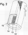
- Fig. 2 shows a cut-through view of an embodiment of the body of a spray drying chamber. From this angle it is possible to see the functional layers of the embodiment.
- the blanket heater 13 On the outer surface of the inner sheet 12 of the spray drying chamber, the blanket heater 13 is positioned. The blanket heater will normally cover all of the surfaces in contact with process gas on the spray drying chamber 3, outlet duct 11 and cyclone 4.
- a layer of insulating material 14 is placed on the outer side of the blanket heater 13.
- the insulating material is covered by a hard plain material e.g. a layer of fully welded stainless steel.
Landscapes
- Chemical & Material Sciences (AREA)
- Engineering & Computer Science (AREA)
- Chemical Kinetics & Catalysis (AREA)
- Organic Chemistry (AREA)
- Mechanical Engineering (AREA)
- General Engineering & Computer Science (AREA)
- Life Sciences & Earth Sciences (AREA)
- Microbiology (AREA)
- Apparatus For Disinfection Or Sterilisation (AREA)
- Drying Of Solid Materials (AREA)
Claims (10)
- Vorrichtung zur Bereitstellung eines teilchenförmigen Materials, umfassend eine Sprühtrocknungskammer (3), Nachbehandlungsausrüstung (4, 5) stromabwärts von der Sprühtrocknungskammer und eine Prozessgasheizvorrichtung (2), die bezüglich der Sprühtrocknungskammer (3) stromaufwärts angeordnet ist, dadurch gekennzeichnet, dass ein Einlassfilter (1), der Mikroorganismen bei einer Temperatur unter 140°C entfernen kann, stromaufwärts von der Prozessgasheizvorrichtung (2) angeordnet ist und dass die Prozessgasheizvorrichtung (2) eine nicht abblätternde Heizvorrichtung ist,
wobei der Einlassfilter (1) ein ULPA-Filter ist. - Vorrichtung nach Anspruch 1, wobei der Einlassfilter einer Dampfsterilisation bei mindestens 121°C für mindestens 15 Minuten widerstehen kann.
- Vorrichtung nach Anspruch 1, wobei die Nachbehandlungsausrüstung einen Gas/Partikelabscheider (4, 5) umfasst.
- Vorrichtung nach Anspruch 3, wobei der Gas/Partikelabscheider (4) ein Zyklon oder ein Textilfilter oder eine Kombination ist, fakultativ gefolgt von einem Staubfilter (5).
- Vorrichtung nach den Ansprüchen 1 bis 4, wobei das System eine Flächenheizung (13) umfasst.
- Vorrichtung nach Anspruch 5, wobei die Flächenheizung (13) eine Heizmatte umfasst.
- Vorrichtung nach Anspruch 6, wobei die Heizmatte aus ein oder mehr einzeln gesteuerten Heizvorrichtungen besteht, die zusammen mindestens 30% der Außenflächen der Ausrüstung, die auf den Innenflächen Kontakt mit dem Prozessgas haben, abdecken.
- Vorrichtung nach den Ansprüchen 1-7, wobei die Sprühtrocknungskammer (3) eine Wartungsöffnung im oberen Teil aufweist.
- Verfahren zum Reinigen und Sterilisieren der Vorrichtung nach den Ansprüchen 1-8, dadurch gekennzeichnet, dass es die folgenden Schritte umfasst:a) die Vorrichtung wird mit reinem Wasser, insbesondere mit Wasser für Injektionszwecke (WFI) gewaschen,b) der Filter und die Heizvorrichtung werden mit Dampf sterilisiert,c) Trockengas bei einer Mindesttemperatur wird für eine Mindestzeit, die von den Sterilisationserfordernissen bestimmt wird, durch die Vorrichtung geleitet,wobei eine ergänzende Flächenheizung (13) während Schritt c) aktiviert wird.
- Verfahren nach Anspruch 9, wobei die Flächenheizung die Form einer Heizmatte hat, die in Kontakt mit der Außenfläche der Produktkontaktflächen der Vorrichtung platziert wird.
Applications Claiming Priority (1)
| Application Number | Priority Date | Filing Date | Title |
|---|---|---|---|
| PCT/DK2007/050042 WO2008122288A1 (en) | 2007-04-10 | 2007-04-10 | Process gas filtration |
Publications (2)
| Publication Number | Publication Date |
|---|---|
| EP2158029A1 EP2158029A1 (de) | 2010-03-03 |
| EP2158029B1 true EP2158029B1 (de) | 2019-05-29 |
Family
ID=38814400
Family Applications (2)
| Application Number | Title | Priority Date | Filing Date |
|---|---|---|---|
| EP07722697.5A Active EP2158029B1 (de) | 2007-04-10 | 2007-04-10 | Prozessgasfilter und verfahren zur reinigung des filters |
| EP08736057A Withdrawn EP2142292A2 (de) | 2007-04-10 | 2008-04-10 | Verfahren zur demontage eines sprühtrocknungssystems |
Family Applications After (1)
| Application Number | Title | Priority Date | Filing Date |
|---|---|---|---|
| EP08736057A Withdrawn EP2142292A2 (de) | 2007-04-10 | 2008-04-10 | Verfahren zur demontage eines sprühtrocknungssystems |
Country Status (4)
| Country | Link |
|---|---|
| US (2) | US8398732B2 (de) |
| EP (2) | EP2158029B1 (de) |
| DK (1) | DK2158029T3 (de) |
| WO (2) | WO2008122288A1 (de) |
Families Citing this family (29)
| Publication number | Priority date | Publication date | Assignee | Title |
|---|---|---|---|---|
| WO2010117976A1 (en) | 2009-04-09 | 2010-10-14 | Entegrion, Inc | Spray-dried blood products and methods of making same |
| US20110142885A1 (en) | 2009-09-16 | 2011-06-16 | Velico Medical, Inc. | Spray-dried human plasma |
| US8407912B2 (en) | 2010-09-16 | 2013-04-02 | Velico Medical, Inc. | Spray dried human plasma |
| CN104959087B (zh) | 2010-04-09 | 2017-08-15 | 帕西拉制药有限公司 | 用于配制大直径合成膜囊泡的方法 |
| EP2632580A2 (de) | 2010-10-29 | 2013-09-04 | Velico Medical, Inc. | System und verfahren zum sprühtrocknen einer flüssigkeit |
| US20140083628A1 (en) | 2012-09-27 | 2014-03-27 | Velico Medical, Inc. | Spray drier assembly for automated spray drying |
| CN103429228B (zh) | 2011-01-05 | 2016-10-26 | 赫士睿股份有限公司 | 万古霉素的喷雾干燥 |
| CN103111153A (zh) * | 2013-03-11 | 2013-05-22 | 常熟理工学院 | 一种除尘方法 |
| CN104043104B (zh) | 2013-03-15 | 2018-07-10 | 浙江创新生物有限公司 | 含盐酸万古霉素的喷雾干粉及其工业化制备方法 |
| CN103505372B (zh) * | 2013-10-21 | 2014-08-13 | 金陵科技学院 | 一种产率高适用范围广的微囊制剂生产设备 |
| US9561184B2 (en) | 2014-09-19 | 2017-02-07 | Velico Medical, Inc. | Methods and systems for multi-stage drying of plasma |
| PL3371536T3 (pl) * | 2015-11-03 | 2020-04-30 | Gea Process Engineering A/S | System suszenia rozpyłowego obejmujący ulepszony zespół łączący i sposób czyszczenia systemu |
| EP3490734B1 (de) * | 2016-07-28 | 2023-04-19 | ExxonMobil Chemical Patents Inc. | Verfahren und vorrichtung zum reinigen eines hochdruckabscheiders |
| CN106620748A (zh) * | 2016-11-17 | 2017-05-10 | 宜春万申制药机械有限公司 | 制药灭菌干燥一体化装置 |
| CA3074324A1 (en) * | 2017-08-31 | 2019-03-07 | Capsugel Belgium Nv | Single-use spray drying components and methods of using the same |
| JP7586495B2 (ja) * | 2019-03-01 | 2024-11-19 | 株式会社カワタ | 粉体のコーティング装置 |
| MA55278A (fr) * | 2019-03-15 | 2022-01-19 | Novo Nordisk As | Procédé de séchage à pulvérisation d'un peptide glp-1 |
| US20220054665A1 (en) * | 2020-07-14 | 2022-02-24 | Goodrich Aerospace Services Private Limited | Disinfection assemblies |
| CN112077326B (zh) * | 2020-08-18 | 2023-06-06 | 苏州鲁信新材料科技有限公司 | 一种制备铜合金粉的雾化设备 |
| CN114504834B (zh) * | 2022-02-24 | 2023-03-07 | 华夏生生药业(北京)有限公司 | 一种葡萄糖酸钙溶液提纯设备及其工艺 |
| US11975274B2 (en) | 2022-09-15 | 2024-05-07 | Velico Medical, Inc. | Blood plasma product |
| US12246266B2 (en) | 2022-09-15 | 2025-03-11 | Velico Medical, Inc. | Disposable for a spray drying system |
| US12246093B2 (en) | 2022-09-15 | 2025-03-11 | Velico Medical, Inc. | Methods for making spray dried plasma |
| US11841189B1 (en) | 2022-09-15 | 2023-12-12 | Velico Medical, Inc. | Disposable for a spray drying system |
| WO2024059770A1 (en) | 2022-09-15 | 2024-03-21 | Velico Medical, Inc. | Rapid spray drying system |
| US12539355B2 (en) | 2022-09-15 | 2026-02-03 | Velico Medical, Inc. | Dryer for a spray drying system |
| US12083447B2 (en) | 2022-09-15 | 2024-09-10 | Velico Medical, Inc. | Alignment of a disposable for a spray drying plasma system |
| US11998861B2 (en) | 2022-09-15 | 2024-06-04 | Velico Medical, Inc. | Usability of a disposable for a spray drying plasma system |
| US12571587B2 (en) | 2022-09-15 | 2026-03-10 | Velico Medical, Inc. | Finishing apparatus for a spray drying system |
Citations (1)
| Publication number | Priority date | Publication date | Assignee | Title |
|---|---|---|---|---|
| US2531343A (en) * | 1944-12-11 | 1950-11-21 | Swift & Co | Manufacture of dried egg material |
Family Cites Families (22)
| Publication number | Priority date | Publication date | Assignee | Title |
|---|---|---|---|---|
| US464904A (en) * | 1891-12-08 | Device for measuring and folding dress goods | ||
| US3754852A (en) * | 1965-08-24 | 1973-08-28 | Dodds T Inc | Apparatus for rotational casting |
| US3771289A (en) * | 1969-06-09 | 1973-11-13 | S Skoli | Collection device for dryer exhaust gases |
| GB1265615A (de) * | 1970-09-10 | 1972-03-01 | ||
| US3835216A (en) * | 1971-10-28 | 1974-09-10 | Huber Corp J M | Methods for production of alkali metal polysilicates |
| US4649037A (en) * | 1985-03-29 | 1987-03-10 | Allied Corporation | Spray-dried inorganic oxides from non-aqueous gels or solutions |
| US4948362A (en) * | 1988-11-14 | 1990-08-14 | Georgia Kaolin Company, Inc. | Energy conserving process for calcining clay |
| US5419351A (en) * | 1993-04-02 | 1995-05-30 | National Semiconductor Corporation | Final rinse/dry system for critical cleaning applications |
| US5762797A (en) * | 1995-12-15 | 1998-06-09 | Patrick; Gilbert | Antimicrobial filter cartridge |
| US6627426B2 (en) * | 1997-02-14 | 2003-09-30 | Invitrogen Corporation | Methods for reducing adventitious agents and toxins and cell culture reagents produced thereby |
| WO1997014288A2 (en) * | 1997-02-20 | 1997-04-24 | Niro A/S | Spray drying method and apparatus and cleaning method for such an apparatus |
| US7264680B2 (en) * | 1997-05-09 | 2007-09-04 | Semitool, Inc. | Process and apparatus for treating a workpiece using ozone |
| US6253463B1 (en) * | 1999-04-26 | 2001-07-03 | Niro A/S | Method of spray drying |
| US6560897B2 (en) * | 1999-05-03 | 2003-05-13 | Acusphere, Inc. | Spray drying apparatus and methods of use |
| US6223455B1 (en) * | 1999-05-03 | 2001-05-01 | Acusphere, Inc. | Spray drying apparatus and methods of use |
| EP1337313A4 (de) * | 2000-10-23 | 2005-01-26 | Henry B Lewin | Vorrichtung und verfahren zur behandlung von druckluft |
| EP1469833B1 (de) * | 2002-02-01 | 2021-05-19 | Bend Research, Inc. | Verfahren zur herstellung homogenisierter sprühgetrockneter fester amorpher wirkstoffdispersionen, das eine modifizierte vorrichtung zur sprühtrocknung verwendet |
| US6962006B2 (en) * | 2002-12-19 | 2005-11-08 | Acusphere, Inc. | Methods and apparatus for making particles using spray dryer and in-line jet mill |
| US20050050759A1 (en) * | 2003-08-11 | 2005-03-10 | Manufacturing And Technology Conversion International, Inc. | Efficient and cost-effective biomass drying |
| US20060048674A1 (en) * | 2004-09-07 | 2006-03-09 | Craig Daniel H | Process for manufacturing thermoplastic materials containing inorganic particulates |
| US20080075777A1 (en) * | 2006-07-31 | 2008-03-27 | Kennedy Michael T | Apparatus and methods for preparing solid particles |
| WO2010006618A1 (en) * | 2008-07-14 | 2010-01-21 | Gea Process Engineering A/S | Spray dryer absorption process for flue gas with entrained coarse particles |
-
2007
- 2007-04-10 DK DK07722697.5T patent/DK2158029T3/da active
- 2007-04-10 US US12/595,448 patent/US8398732B2/en not_active Expired - Fee Related
- 2007-04-10 WO PCT/DK2007/050042 patent/WO2008122288A1/en not_active Ceased
- 2007-04-10 EP EP07722697.5A patent/EP2158029B1/de active Active
-
2008
- 2008-04-10 EP EP08736057A patent/EP2142292A2/de not_active Withdrawn
- 2008-04-10 WO PCT/EP2008/054336 patent/WO2008122663A2/en not_active Ceased
- 2008-04-10 US US12/595,410 patent/US20100069701A1/en not_active Abandoned
Patent Citations (1)
| Publication number | Priority date | Publication date | Assignee | Title |
|---|---|---|---|---|
| US2531343A (en) * | 1944-12-11 | 1950-11-21 | Swift & Co | Manufacture of dried egg material |
Also Published As
| Publication number | Publication date |
|---|---|
| WO2008122663A3 (en) | 2009-11-05 |
| US20100069701A1 (en) | 2010-03-18 |
| US20100116294A1 (en) | 2010-05-13 |
| EP2158029A1 (de) | 2010-03-03 |
| DK2158029T3 (da) | 2019-08-19 |
| EP2142292A2 (de) | 2010-01-13 |
| WO2008122288A1 (en) | 2008-10-16 |
| US8398732B2 (en) | 2013-03-19 |
| WO2008122663A2 (en) | 2008-10-16 |
Similar Documents
| Publication | Publication Date | Title |
|---|---|---|
| EP2158029B1 (de) | Prozessgasfilter und verfahren zur reinigung des filters | |
| EP3379152B1 (de) | Kochgerät und verfahren zur übertragung von wärmeenergie aus einer dunstabzugshaube | |
| US20120079946A1 (en) | Self-cleaning vapor-condensing grease baffle filter | |
| EP1037856B1 (de) | Verfahren und vorrichtung zur herstellung reines wasser | |
| CA2043093C (en) | Method and apparatus for combined spray drying and gas cleaning | |
| RU2184329C2 (ru) | Фильтр-теплообменник (варианты) | |
| TW425313B (en) | Method and apparatus for cleaning filters contaminated by polymers and hot-melting resins, in stu, without removing the filtering elements | |
| WO1995028628A1 (en) | A gas sampling probe | |
| JPH0217916A (ja) | 液体ベシクルを含有する汚染ガスの濾過方法とその装置 | |
| CN107129089B (zh) | 一种净水设备 | |
| KR102310581B1 (ko) | 유증기 유분 제거 장치 | |
| CN102700027B (zh) | 一种干燥聚四氟乙烯的系统及其应用 | |
| CN209010307U (zh) | 一种净水设备 | |
| JPH08261670A (ja) | 分解出来る多重胴式熱交換器 | |
| JP4612557B2 (ja) | フィルタ洗浄方法 | |
| CN212594631U (zh) | 一种联苯热交换系统 | |
| JPS60501022A (ja) | 蓄熱式の熱交換系 | |
| CN213713402U (zh) | 一种生物实验室空气处理系统 | |
| CN121197946B (zh) | 一种高温含尘有机蒸汽的回收方法与装置 | |
| JP2015021708A (ja) | 多管式熱交換器 | |
| JP7555281B2 (ja) | 集塵装置 | |
| CN113117356B (zh) | 一种溶液内循环蒸发系统 | |
| CN218900825U (zh) | 一种千页热同步交换器 | |
| JP4414555B2 (ja) | 高温水用フィルタ | |
| JPS5864487A (ja) | 過熱蒸気を含むガス体の熱交換方法およびその装置 |
Legal Events
| Date | Code | Title | Description |
|---|---|---|---|
| PUAI | Public reference made under article 153(3) epc to a published international application that has entered the european phase |
Free format text: ORIGINAL CODE: 0009012 |
|
| 17P | Request for examination filed |
Effective date: 20091104 |
|
| AK | Designated contracting states |
Kind code of ref document: A1 Designated state(s): AT BE BG CH CY CZ DE DK EE ES FI FR GB GR HU IE IS IT LI LT LU LV MC MT NL PL PT RO SE SI SK TR |
|
| AX | Request for extension of the european patent |
Extension state: AL BA HR MK RS |
|
| RIN1 | Information on inventor provided before grant (corrected) |
Inventor name: RASMUSSEN, SOREN, STEN Inventor name: TUROK, ROBERT |
|
| DAX | Request for extension of the european patent (deleted) | ||
| STAA | Information on the status of an ep patent application or granted ep patent |
Free format text: STATUS: EXAMINATION IS IN PROGRESS |
|
| 17Q | First examination report despatched |
Effective date: 20180205 |
|
| RIC1 | Information provided on ipc code assigned before grant |
Ipc: F26B 21/00 20060101ALI20180829BHEP Ipc: B01J 2/04 20060101ALI20180829BHEP Ipc: B01J 2/02 20060101AFI20180829BHEP Ipc: B01D 1/18 20060101ALI20180829BHEP Ipc: F26B 3/12 20060101ALI20180829BHEP |
|
| GRAP | Despatch of communication of intention to grant a patent |
Free format text: ORIGINAL CODE: EPIDOSNIGR1 |
|
| STAA | Information on the status of an ep patent application or granted ep patent |
Free format text: STATUS: GRANT OF PATENT IS INTENDED |
|
| INTG | Intention to grant announced |
Effective date: 20181031 |
|
| RIN1 | Information on inventor provided before grant (corrected) |
Inventor name: RASMUSSEN, SOEREN, STEN Inventor name: TUROK, ROBERT |
|
| GRAS | Grant fee paid |
Free format text: ORIGINAL CODE: EPIDOSNIGR3 |
|
| GRAA | (expected) grant |
Free format text: ORIGINAL CODE: 0009210 |
|
| STAA | Information on the status of an ep patent application or granted ep patent |
Free format text: STATUS: THE PATENT HAS BEEN GRANTED |
|
| AK | Designated contracting states |
Kind code of ref document: B1 Designated state(s): AT BE BG CH CY CZ DE DK EE ES FI FR GB GR HU IE IS IT LI LT LU LV MC MT NL PL PT RO SE SI SK TR |
|
| REG | Reference to a national code |
Ref country code: GB Ref legal event code: FG4D |
|
| REG | Reference to a national code |
Ref country code: CH Ref legal event code: EP |
|
| REG | Reference to a national code |
Ref country code: DE Ref legal event code: R096 Ref document number: 602007058482 Country of ref document: DE |
|
| REG | Reference to a national code |
Ref country code: AT Ref legal event code: REF Ref document number: 1137951 Country of ref document: AT Kind code of ref document: T Effective date: 20190615 |
|
| REG | Reference to a national code |
Ref country code: IE Ref legal event code: FG4D |
|
| REG | Reference to a national code |
Ref country code: DK Ref legal event code: T3 Effective date: 20190816 |
|
| REG | Reference to a national code |
Ref country code: NL Ref legal event code: MP Effective date: 20190529 |
|
| REG | Reference to a national code |
Ref country code: LT Ref legal event code: MG4D |
|
| PG25 | Lapsed in a contracting state [announced via postgrant information from national office to epo] |
Ref country code: ES Free format text: LAPSE BECAUSE OF FAILURE TO SUBMIT A TRANSLATION OF THE DESCRIPTION OR TO PAY THE FEE WITHIN THE PRESCRIBED TIME-LIMIT Effective date: 20190529 Ref country code: PT Free format text: LAPSE BECAUSE OF FAILURE TO SUBMIT A TRANSLATION OF THE DESCRIPTION OR TO PAY THE FEE WITHIN THE PRESCRIBED TIME-LIMIT Effective date: 20190930 Ref country code: LT Free format text: LAPSE BECAUSE OF FAILURE TO SUBMIT A TRANSLATION OF THE DESCRIPTION OR TO PAY THE FEE WITHIN THE PRESCRIBED TIME-LIMIT Effective date: 20190529 Ref country code: FI Free format text: LAPSE BECAUSE OF FAILURE TO SUBMIT A TRANSLATION OF THE DESCRIPTION OR TO PAY THE FEE WITHIN THE PRESCRIBED TIME-LIMIT Effective date: 20190529 Ref country code: SE Free format text: LAPSE BECAUSE OF FAILURE TO SUBMIT A TRANSLATION OF THE DESCRIPTION OR TO PAY THE FEE WITHIN THE PRESCRIBED TIME-LIMIT Effective date: 20190529 |
|
| PG25 | Lapsed in a contracting state [announced via postgrant information from national office to epo] |
Ref country code: LV Free format text: LAPSE BECAUSE OF FAILURE TO SUBMIT A TRANSLATION OF THE DESCRIPTION OR TO PAY THE FEE WITHIN THE PRESCRIBED TIME-LIMIT Effective date: 20190529 Ref country code: GR Free format text: LAPSE BECAUSE OF FAILURE TO SUBMIT A TRANSLATION OF THE DESCRIPTION OR TO PAY THE FEE WITHIN THE PRESCRIBED TIME-LIMIT Effective date: 20190830 Ref country code: BG Free format text: LAPSE BECAUSE OF FAILURE TO SUBMIT A TRANSLATION OF THE DESCRIPTION OR TO PAY THE FEE WITHIN THE PRESCRIBED TIME-LIMIT Effective date: 20190829 |
|
| REG | Reference to a national code |
Ref country code: AT Ref legal event code: MK05 Ref document number: 1137951 Country of ref document: AT Kind code of ref document: T Effective date: 20190529 |
|
| PG25 | Lapsed in a contracting state [announced via postgrant information from national office to epo] |
Ref country code: NL Free format text: LAPSE BECAUSE OF FAILURE TO SUBMIT A TRANSLATION OF THE DESCRIPTION OR TO PAY THE FEE WITHIN THE PRESCRIBED TIME-LIMIT Effective date: 20190529 Ref country code: RO Free format text: LAPSE BECAUSE OF FAILURE TO SUBMIT A TRANSLATION OF THE DESCRIPTION OR TO PAY THE FEE WITHIN THE PRESCRIBED TIME-LIMIT Effective date: 20190529 Ref country code: CZ Free format text: LAPSE BECAUSE OF FAILURE TO SUBMIT A TRANSLATION OF THE DESCRIPTION OR TO PAY THE FEE WITHIN THE PRESCRIBED TIME-LIMIT Effective date: 20190529 Ref country code: EE Free format text: LAPSE BECAUSE OF FAILURE TO SUBMIT A TRANSLATION OF THE DESCRIPTION OR TO PAY THE FEE WITHIN THE PRESCRIBED TIME-LIMIT Effective date: 20190529 Ref country code: AT Free format text: LAPSE BECAUSE OF FAILURE TO SUBMIT A TRANSLATION OF THE DESCRIPTION OR TO PAY THE FEE WITHIN THE PRESCRIBED TIME-LIMIT Effective date: 20190529 Ref country code: SK Free format text: LAPSE BECAUSE OF FAILURE TO SUBMIT A TRANSLATION OF THE DESCRIPTION OR TO PAY THE FEE WITHIN THE PRESCRIBED TIME-LIMIT Effective date: 20190529 |
|
| REG | Reference to a national code |
Ref country code: DE Ref legal event code: R097 Ref document number: 602007058482 Country of ref document: DE |
|
| PG25 | Lapsed in a contracting state [announced via postgrant information from national office to epo] |
Ref country code: TR Free format text: LAPSE BECAUSE OF FAILURE TO SUBMIT A TRANSLATION OF THE DESCRIPTION OR TO PAY THE FEE WITHIN THE PRESCRIBED TIME-LIMIT Effective date: 20190529 |
|
| PLBE | No opposition filed within time limit |
Free format text: ORIGINAL CODE: 0009261 |
|
| STAA | Information on the status of an ep patent application or granted ep patent |
Free format text: STATUS: NO OPPOSITION FILED WITHIN TIME LIMIT |
|
| PG25 | Lapsed in a contracting state [announced via postgrant information from national office to epo] |
Ref country code: PL Free format text: LAPSE BECAUSE OF FAILURE TO SUBMIT A TRANSLATION OF THE DESCRIPTION OR TO PAY THE FEE WITHIN THE PRESCRIBED TIME-LIMIT Effective date: 20190529 |
|
| 26N | No opposition filed |
Effective date: 20200303 |
|
| PG25 | Lapsed in a contracting state [announced via postgrant information from national office to epo] |
Ref country code: SI Free format text: LAPSE BECAUSE OF FAILURE TO SUBMIT A TRANSLATION OF THE DESCRIPTION OR TO PAY THE FEE WITHIN THE PRESCRIBED TIME-LIMIT Effective date: 20190529 |
|
| REG | Reference to a national code |
Ref country code: DE Ref legal event code: R119 Ref document number: 602007058482 Country of ref document: DE |
|
| REG | Reference to a national code |
Ref country code: DK Ref legal event code: EBP Effective date: 20200430 |
|
| PG25 | Lapsed in a contracting state [announced via postgrant information from national office to epo] |
Ref country code: MC Free format text: LAPSE BECAUSE OF FAILURE TO SUBMIT A TRANSLATION OF THE DESCRIPTION OR TO PAY THE FEE WITHIN THE PRESCRIBED TIME-LIMIT Effective date: 20190529 |
|
| REG | Reference to a national code |
Ref country code: CH Ref legal event code: PL |
|
| PG25 | Lapsed in a contracting state [announced via postgrant information from national office to epo] |
Ref country code: LU Free format text: LAPSE BECAUSE OF NON-PAYMENT OF DUE FEES Effective date: 20200410 Ref country code: LI Free format text: LAPSE BECAUSE OF NON-PAYMENT OF DUE FEES Effective date: 20200430 Ref country code: CH Free format text: LAPSE BECAUSE OF NON-PAYMENT OF DUE FEES Effective date: 20200430 Ref country code: FR Free format text: LAPSE BECAUSE OF NON-PAYMENT OF DUE FEES Effective date: 20200430 Ref country code: DE Free format text: LAPSE BECAUSE OF NON-PAYMENT OF DUE FEES Effective date: 20201103 |
|
| REG | Reference to a national code |
Ref country code: BE Ref legal event code: MM Effective date: 20200430 |
|
| PG25 | Lapsed in a contracting state [announced via postgrant information from national office to epo] |
Ref country code: BE Free format text: LAPSE BECAUSE OF NON-PAYMENT OF DUE FEES Effective date: 20200430 |
|
| GBPC | Gb: european patent ceased through non-payment of renewal fee |
Effective date: 20200410 |
|
| PG25 | Lapsed in a contracting state [announced via postgrant information from national office to epo] |
Ref country code: DK Free format text: LAPSE BECAUSE OF NON-PAYMENT OF DUE FEES Effective date: 20200430 Ref country code: IE Free format text: LAPSE BECAUSE OF NON-PAYMENT OF DUE FEES Effective date: 20200410 Ref country code: GB Free format text: LAPSE BECAUSE OF NON-PAYMENT OF DUE FEES Effective date: 20200410 |
|
| PG25 | Lapsed in a contracting state [announced via postgrant information from national office to epo] |
Ref country code: IT Free format text: LAPSE BECAUSE OF NON-PAYMENT OF DUE FEES Effective date: 20200410 |
|
| PG25 | Lapsed in a contracting state [announced via postgrant information from national office to epo] |
Ref country code: MT Free format text: LAPSE BECAUSE OF FAILURE TO SUBMIT A TRANSLATION OF THE DESCRIPTION OR TO PAY THE FEE WITHIN THE PRESCRIBED TIME-LIMIT Effective date: 20190529 Ref country code: CY Free format text: LAPSE BECAUSE OF FAILURE TO SUBMIT A TRANSLATION OF THE DESCRIPTION OR TO PAY THE FEE WITHIN THE PRESCRIBED TIME-LIMIT Effective date: 20190529 |
|
| PG25 | Lapsed in a contracting state [announced via postgrant information from national office to epo] |
Ref country code: IS Free format text: LAPSE BECAUSE OF FAILURE TO SUBMIT A TRANSLATION OF THE DESCRIPTION OR TO PAY THE FEE WITHIN THE PRESCRIBED TIME-LIMIT Effective date: 20190929 |