EP2158121B1 - Schiff - Google Patents
Schiff Download PDFInfo
- Publication number
- EP2158121B1 EP2158121B1 EP09757666.4A EP09757666A EP2158121B1 EP 2158121 B1 EP2158121 B1 EP 2158121B1 EP 09757666 A EP09757666 A EP 09757666A EP 2158121 B1 EP2158121 B1 EP 2158121B1
- Authority
- EP
- European Patent Office
- Prior art keywords
- plate
- ship
- levelling
- protective plate
- container
- Prior art date
- Legal status (The legal status is an assumption and is not a legal conclusion. Google has not performed a legal analysis and makes no representation as to the accuracy of the status listed.)
- Not-in-force
Links
- 230000001681 protective effect Effects 0.000 claims description 53
- 239000000565 sealant Substances 0.000 claims description 19
- 229910000831 Steel Inorganic materials 0.000 claims description 11
- 239000010959 steel Substances 0.000 claims description 11
- 238000010276 construction Methods 0.000 claims description 7
- 239000000463 material Substances 0.000 claims description 5
- 239000010426 asphalt Substances 0.000 claims description 3
- 239000011120 plywood Substances 0.000 claims description 3
- 239000004575 stone Substances 0.000 description 2
- 238000003466 welding Methods 0.000 description 2
- 239000005995 Aluminium silicate Substances 0.000 description 1
- 235000012211 aluminium silicate Nutrition 0.000 description 1
- 239000000571 coke Substances 0.000 description 1
- 230000000694 effects Effects 0.000 description 1
- 239000000945 filler Substances 0.000 description 1
- NLYAJNPCOHFWQQ-UHFFFAOYSA-N kaolin Chemical compound O.O.O=[Al]O[Si](=O)O[Si](=O)O[Al]=O NLYAJNPCOHFWQQ-UHFFFAOYSA-N 0.000 description 1
- 238000004519 manufacturing process Methods 0.000 description 1
- 239000000203 mixture Substances 0.000 description 1
- 238000007789 sealing Methods 0.000 description 1
- 229910052710 silicon Inorganic materials 0.000 description 1
- 239000010703 silicon Substances 0.000 description 1
- 239000010421 standard material Substances 0.000 description 1
Images
Classifications
-
- B—PERFORMING OPERATIONS; TRANSPORTING
- B63—SHIPS OR OTHER WATERBORNE VESSELS; RELATED EQUIPMENT
- B63B—SHIPS OR OTHER WATERBORNE VESSELS; EQUIPMENT FOR SHIPPING
- B63B3/00—Hulls characterised by their structure or component parts
- B63B3/14—Hull parts
- B63B3/62—Double bottoms; Tank tops
-
- B—PERFORMING OPERATIONS; TRANSPORTING
- B63—SHIPS OR OTHER WATERBORNE VESSELS; RELATED EQUIPMENT
- B63B—SHIPS OR OTHER WATERBORNE VESSELS; EQUIPMENT FOR SHIPPING
- B63B25/00—Load-accommodating arrangements, e.g. stowing, trimming; Vessels characterised thereby
- B63B25/002—Load-accommodating arrangements, e.g. stowing, trimming; Vessels characterised thereby for goods other than bulk goods
- B63B25/004—Load-accommodating arrangements, e.g. stowing, trimming; Vessels characterised thereby for goods other than bulk goods for containers
-
- B—PERFORMING OPERATIONS; TRANSPORTING
- B63—SHIPS OR OTHER WATERBORNE VESSELS; RELATED EQUIPMENT
- B63B—SHIPS OR OTHER WATERBORNE VESSELS; EQUIPMENT FOR SHIPPING
- B63B11/00—Interior subdivision of hulls
- B63B11/04—Constructional features of bunkers, e.g. structural fuel tanks, or ballast tanks, e.g. with elastic walls
-
- B—PERFORMING OPERATIONS; TRANSPORTING
- B63—SHIPS OR OTHER WATERBORNE VESSELS; RELATED EQUIPMENT
- B63B—SHIPS OR OTHER WATERBORNE VESSELS; EQUIPMENT FOR SHIPPING
- B63B25/00—Load-accommodating arrangements, e.g. stowing, trimming; Vessels characterised thereby
-
- B—PERFORMING OPERATIONS; TRANSPORTING
- B63—SHIPS OR OTHER WATERBORNE VESSELS; RELATED EQUIPMENT
- B63B—SHIPS OR OTHER WATERBORNE VESSELS; EQUIPMENT FOR SHIPPING
- B63B25/00—Load-accommodating arrangements, e.g. stowing, trimming; Vessels characterised thereby
- B63B25/02—Load-accommodating arrangements, e.g. stowing, trimming; Vessels characterised thereby for bulk goods
-
- B—PERFORMING OPERATIONS; TRANSPORTING
- B63—SHIPS OR OTHER WATERBORNE VESSELS; RELATED EQUIPMENT
- B63B—SHIPS OR OTHER WATERBORNE VESSELS; EQUIPMENT FOR SHIPPING
- B63B25/00—Load-accommodating arrangements, e.g. stowing, trimming; Vessels characterised thereby
- B63B25/28—Load-accommodating arrangements, e.g. stowing, trimming; Vessels characterised thereby for deck loads
Definitions
- the invention relates to a ship comprising a cargo space on the bottom of which there is a bottom plate, whereby above the level formed by the bottom plate there are a plurality of container supports for receiving and securing containers and cargo transportation stands to the cargo space, the upper end of the container supports being at a distance equal to the height of the container supports from the bottom plate.
- bulk goods may be any loose/bulk goods: typically it could be e.g. coke, grain or kaolin, but it may also consist of scrapped steel.
- Applicability of said ships for transporting goods transportation stands is also limited to some extent, because they are not suitable for transporting long and/or heavily loaded, e.g. loaded with steel coils, goods transportation stands.
- the reason for not being suitable for use of this kind is that heavily loaded goods transportation stands would bend and could at the same time be damaged as the upper level of the container supports is higher up than the bottom plate of the ship.
- the object of the invention is to provide a ship that is suitable for transporting both containers and bulk goods.
- a ship according to the invention which is characterized in that on top of the bottom plate of the cargo space is arranged a levelling construction, on top of which there is arranged a protective plate, in which there are provided lead-through points for the container supports so that the container supports are surrounded by the protective plate and an upper level of the protective plate is at a level of the upper end of the container supports.
- the basic idea of the invention is to utilize a levelling construction whereby the bottom level of the cargo space is raised higher so that, in view of the mass of the protective plate, only small amounts of a hard-wearing protective plate suitable for handling of bulk goods will be needed, whereby the bottom of the cargo space will be at the same time technically easy to manufacture by using readily available standard materials which are cheaper than the protective plate.
- the levelling construction is adapted to provide adequate support for the protective plate.
- the container supports must not rise above the bottom of the cargo space of the ship, because in that case the cargo space of the ship could not be unloaded with a grab, which could easily get caught to the container supports and cause damage.
- the surface formed by the protective plate, the container supports and optional sealant has to be even and strong.
- the levelling construction is a levelling plate in which there are provided through holes for the container supports and which surrounds the container supports.
- the levelling plate is made of material lighter than steel plate.
- the protective plate is a steel plate.
- a sealant is arranged between the walls of the through holes and the container supports.
- the sealant prevents the access of transported bulk goods and moisture beneath the levelling plate.
- the protective plate is preferably welded to the container support in order to hold the protective plate in place, whereby it is most preferable to weld the protective plate also to support pieces that are secured, advantageously by welding, to the bottom plate of the cargo space to ensure good attachment of the protective plate to the bottom plate.
- Sealant is added around the support pieces between the support pieces and the levelling plate to prevent the access of the transported bulk goods and moisture beneath the levelling plate.
- sealant is added between the level formed by the upper surface of the support pieces and the upper surface of the protective plate to prevent access of the transported bulk goods and moisture beneath the protective plate.
- the sealant may be rubberized bitumen, because it is easy to apply to the point to be sealed, among other things.
- the most important advantage of the ship according to the invention is that, in addition to containers and various goods transportation stands, it may be used for transporting bulk goods, whereby the bottom of the cargo space of the ship is reinforced to endure the handling of bulk goods.
- An essential advantage is also that it is easy to provide.
- the ship of Figure 1 is suitable for transporting containers 1 and stands.
- container supports on the bottom 3 of the ship's cargo space 2, there are arranged a large number of container supports, on top of which the containers 1 are secured.
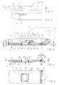
- Reference numeral 5 denotes the container supports in Figure 2 .
- the container support may be called a container shoe.
- the structure of the bottom 3 of the ship's cargo space 1 appears from Figures 3 to 5 .
- the bottom 3 of the cargo space comprises an even, continuous bottom steel plate 4, on top of which is welded (or otherwise fixedly secured or arranged) a plurality of container supports 5.
- Figures 3 to 5 only show one container support 5.
- the container support 5 of the figure comprises four attachment points 6 for attachment means, wherewith the container (or alternatively a goods transportation stand) is attached to the bottom of the cargo space. Attachment means are not shown, because they may be, and preferably also are, of a conventional type.
- the attachment points 6 are recesses, in which the attachment means are engaged. It is possible to attach corners of four containers to the container support of Figure 3 . Alternatively, it is conceivable to use container supports having attachment points for attaching the corners of only two containers, or only one attachment point allowing attachment of the corner of only one container.
- the thickness S of the bottom plate 4 is 10 mm, for instance. Typically S is 8 to 12 mm, depending on the ship.
- the height H1 of the container support 5 protruding from the bottom plate 4 is 30 mm, for instance, whereby the upper end of the container support is at a distance H1 from the level defined by the bottom plate.
- the height H1 of the container support 5 may vary depending on the type of the container support.
- the levelling plate 7 is provided by a plurality of levelling plate portions set side by side.
- the levelling plate portions need not be attached to the bottom plate 4, but they are preferably loose on top of the bottom plate 4.
- the levelling plate portions may be 1.2 m x 2 m in size, or in any other available plate size.
- the levelling plate 7 may preferably be a plywood plate, waterproof plywood being particularly preferable.
- the levelling plate 7 substantially covers the entire bottom plate 4, whereby its surface area substantially corresponds to that of the bottom plate.
- the surface area of the levelling plate 7 is, however, smaller than the surface area of the bottom plate 4, because holes (through holes) are provided in the levelling plate at the location of container supports 5.
- Edges or walls of the holes are denoted by reference numeral 8 in Figure 4 .
- sealant M1 it is preferable to use rubberized bitumen, because it is easy to pour in when warm, and consequently it is easy to provide a structure that seals to the effect that moisture has no access beneath the levelling plate 7.
- the sealant M1 may be silicon.
- the levelling plate 7 should comprise through holes (not shown) at the location of manholes, if any, as well as through holes (not shown) for other required lead-through points.
- the thickness S1 of the levelling plate 7 is 20 mm, for instance.
- the thickness S1 of the levelling plate 7 is preferably selected according to the height of the container support 5. The higher the container support 5, the thicker the levelling plate 7 to be used.
- the protective plate 9 On top of the levelling plate 7 there is a protective plate 9.
- the protective plate 9 consists of several juxtaposed protective plate portions.
- the protective plate portions may be e.g. 2 m x 4 m in size, or in any available plate size.
- the protective plate may preferably be a steel plate consisting of several steel plate portions welded to one another. Steel resists well the wear, to which the cargo space is subjected when it is used for bulk goods.
- the protective plate 9 covers substantially the entire bottom plate 4, whereby its surface area substantially corresponds to that of the bottom plate.
- the protective plate 9 comprises holes at the location of container supports 5.
- the diameter of the holes which may be called lead-through points 12, is slightly longer than the length of a side of the container support 5, whereby minor gaps will be formed between the container support 5 and the protective plate 9.
- the protective plate 9 is welded to the container support 5, through which (in addition to the support pieces 11 described below) the protective plate is partly attached to the bottom plate 4.
- Welding points are denoted by reference numeral 10 in Figure 3 .
- the welds are provided in the midpoint of all sides of the container support 5. Small gaps between the container shoe 5 and the protective plate surrounding it are filled with sealant M2.
- the width of the gaps i.e. the width of the sealant M2, is 10 mm, for instance.
- the upper surface of the protective plate 9 is at the same level with upper end (upper surface) of the container support 5, whereby the thickness S2 of the protective plate 9 is the height H1 of the container support 5 minus the thickness S1 of the levelling plate 7. If H1 is 30 mm and S1 is 15 mm, the thickness of the protective plate 9 is 15 mm. It is conceivable that the thickness of the protective plate is preferably 15 to 20 mm. In that case the thickness of a filler plate 7 is preferably 20 to 80 %, and more preferably 40 to 75 % of the height H1 of the container support 5, depending on the height of the container support.
- FIG. 3 It also appears from Figures 3 to 5 that on top of the bottom plate 4 there are arranged support pieces 11.
- the support pieces 11, which are preferably pieces of steel, are welded to the bottom plate 4.
- Weld joints are depicted in Figure 3 by reference numeral 14.
- the height H2 of the support pieces 11 is greater than thickness S1 of the levelling plate 7 but smaller than the total thickness S1 + S2 of the levelling plate 7 and the protective plate 9.
- the protective plate (protective plate portions) is welded to the support pieces 11, whereby the protective plate 9 is also attached to the bottom plate (i.e. in addition to container support 5) through the support pieces 11.
- Weld joints are depicted in Figure by reference numeral 13.
- the purpose of the support pieces 11 is thus to attach the edge areas of the protective plate 9 (protective plaste portions) to the bottom plate 4 and to support the protective plate (protective plate portions) and to provide an even and strong protective plate 9.
- the support pieces are placed in alignment on top of the bottom plate 4.
- the levelling plate 7 levelling plate portions
- the sealant M3 is not shown in Figure 3 in order to better reveal the structure of the bottom 3. However, in Figures 3 and 5 the sealant M3 is shown.
- the width L of the support pieces 11 is 20 mm, for instance. It is assumed that the width L is preferably 10 to 30 mm and more preferably 10 to 20 mm. If the width L is excessive, the grab wherewith bulk goods is unloaded from the cargo space may get caught to the sealant M3 and the edge of the protective plate close to the support piece 11, and thus damage the protective plate 9.
- the number and exact location of the support pieces 11 are not described herein, because they are ship-specific and it is not difficult for a person skilled in the art to design the location and number of the support pieces to be suitable for the use.
- the levelling plate may be, for instance, a plate of rubber mixture or cast stone material, such as concrete. When made of rubber or cast stone material, the levelling plate may more adequately be called a levelling construction.
Landscapes
- Chemical & Material Sciences (AREA)
- Engineering & Computer Science (AREA)
- Combustion & Propulsion (AREA)
- Mechanical Engineering (AREA)
- Ocean & Marine Engineering (AREA)
- Auxiliary Methods And Devices For Loading And Unloading (AREA)
- Filling Or Discharging Of Gas Storage Vessels (AREA)
Claims (15)
- Schiff, das einen Frachtraum (2) umfasst, an dessen Boden (3) sich eine Bodenplatte (4) befindet, wobei sich oberhalb der durch die Bodenplatte gebildeten Ebene mehrere Containerauflagen (5) befinden, um Container und Frachtbeförderungsgestelle aufzunehmen und an dem Frachtraum (2) zu befestigen, wobei sich das obere Ende der Containerauflagen (5) in einem Abstand, welcher der Höhe (H1) der Containerauflagen (5) bleich ist, von der Bodenplatte (4) befindet, dadurch gekennzeichnet, dass oben auf der Bodenplatte (4) des Frachtraums eine Nivellierkonstruktion (7) angeordnet ist, auf der eine Schutzplatte (9) angeordnet ist, in der Durchführungspunkte (12) für die Containerauflagen (5) bereitgestellt werden, so dass die Containerauflagen durch die Schutzplatte (9) umschlossen werden und sich eine obere Ebene der Schutzplatte (9) auf einer Ebene des oberen Endes der Containerauflagen (5) befindet.
- Schiff nach Anspruch 1, dadurch gekennzeichnet, dass die Nivellierkonstruktion eine Nivellierplatte (7) ist, in der Durchgangslöcher (8) für Containerauflagen (5) bereitgestellt werden.
- Schiff nach Anspruch 2, dadurch gekenntzeichnet, dass zwischen den Wänden, welche die Durchgangslöcher (8) in der Nivellierplatte (7) definierten, und den Containerauflagen (5) ein Dichtungsmaterial (M1) angeordnet ist .
- Schiff nach Anspruch 1 order 2, dadurch gekennzeichnet, dass die Schutzplatte (9) an die Containerauflagen (5) geschweißt (10) ist.
- Schliff nach Anspruch 1 order 2, dadurch gekennzeichnet, dass oben auf der Bodenplatte (4) eine Anzahl von Auflagestücken (11) befestigt ist, an welche die Schutzplatte (9) geschweißt ist.
- Schiff nach Anspruch 5, dadurch gekennzeichnet, dass die Höhe (H2) der Auflagestücke (11) größer als die Dicke (S1) der Nivellierplatte (7) und kleiner als die Gesamtdicke (S1 + S2) der Nivellierplatte und der Schutzplatte (9) ist.
- Schiff nach Anspruch 6, dadurch gekennzeichnet, dass zwischen der oberen Fläche der Auflagestücke (11) und der oberen Fläche der Schutzplatte (9) ein Dichtungsmaterial (M3) derart angeordnet ist, dass sich die obere Ebene der Dichtungsmaterial grob auf der gleichen Ebene mit der oberen Fläche der Schutzplatte befindet.
- Schiff nach einem der vorhergehenden Ansprüche 5 bis 7, dadurch gekennzeichnet, dass die Breite (L) der Auflagerstücke (11) 10 bis 30 mm beträgt.
- Schiff nach Anspruch 2, dadurch gekennzeichet, dass die Nivellierplatte (7) aus mehreren Nivellierplattenabschnitten besteht und die Schutzplatte (9) aus mehreren Schutzplattenabschnitten besteht.
- Schiff nach Anspruch 2, dadurch gekennzeichnet, dass die Nivellierplatte (7) aus einem Werkstoff hergestellt ist, der leichter als Stahlblech ist.
- Schiff nach Anspruch 2, dadurch gekennzeichnet, dass die Nivellierplatte (7) aus Sperrholz ist.
- Schiff nach einem der vorhergehenden Ansprüche 2 bis 11, dadurch gekennzeichet, dass die Dicke (S1) der Nivellierplatte (7) 20 bis 80 % der Höhe (H1) der Containerauflage (5) beträgt.
- Schiff nach Anspruch 12, dadurch gekennzeichnet, dass die Dicke der Nivellierplatte (7) 40 bis 75 % der Höhe (H1) der Containerauflage (5) beträgt.
- Schiff nach Anspruch 1, dadurch gekennzeichnet, dass die Schutzplatte (9) aus Stahlblech besteht.
- Schliff nach Anspruch 3 order 7, dadurch gekennzeichnet, dass das Dichtungsmaterial (M1, M3) gummiertes Bitumen ist.
Priority Applications (1)
| Application Number | Priority Date | Filing Date | Title |
|---|---|---|---|
| PL09757666T PL2158121T3 (pl) | 2008-06-05 | 2009-05-27 | Statek |
Applications Claiming Priority (2)
| Application Number | Priority Date | Filing Date | Title |
|---|---|---|---|
| FI20085554A FI120532B (fi) | 2008-06-05 | 2008-06-05 | Laiva |
| PCT/FI2009/050445 WO2009147288A1 (en) | 2008-06-05 | 2009-05-27 | Ship |
Publications (3)
| Publication Number | Publication Date |
|---|---|
| EP2158121A1 EP2158121A1 (de) | 2010-03-03 |
| EP2158121A4 EP2158121A4 (de) | 2013-04-03 |
| EP2158121B1 true EP2158121B1 (de) | 2014-04-30 |
Family
ID=39589320
Family Applications (1)
| Application Number | Title | Priority Date | Filing Date |
|---|---|---|---|
| EP09757666.4A Not-in-force EP2158121B1 (de) | 2008-06-05 | 2009-05-27 | Schiff |
Country Status (5)
| Country | Link |
|---|---|
| EP (1) | EP2158121B1 (de) |
| CN (1) | CN101808888B (de) |
| FI (1) | FI120532B (de) |
| PL (1) | PL2158121T3 (de) |
| WO (1) | WO2009147288A1 (de) |
Families Citing this family (1)
| Publication number | Priority date | Publication date | Assignee | Title |
|---|---|---|---|---|
| CN103192838A (zh) * | 2013-03-28 | 2013-07-10 | 齐齐哈尔轨道交通装备有限责任公司 | 可拆卸货物运输板及集装箱-平板两用铁路货车 |
Family Cites Families (8)
| Publication number | Priority date | Publication date | Assignee | Title |
|---|---|---|---|---|
| NL224064A (de) * | 1957-01-16 | |||
| US3082726A (en) * | 1958-07-09 | 1963-03-26 | Conch Int Methane Ltd | Insulated floor construction and elements |
| DE2001757A1 (de) * | 1969-11-06 | 1971-05-13 | Thesen Mathias Werft | Containerbefestigung auf Schiffen |
| GB1306805A (en) * | 1970-01-01 | 1973-02-14 | Cole E C | Retractable retaining devices for freight containers |
| JPS5813392B2 (ja) * | 1977-12-03 | 1983-03-14 | 三井造船株式会社 | 船倉内底板のコンテナソケツトの取付方法 |
| GB2070523B (en) * | 1980-02-28 | 1984-02-08 | Pickles Eng Ltd Dennis | Cargo securing system for a marine cargo vessel |
| US5673956A (en) * | 1993-10-06 | 1997-10-07 | Penda Corporation | Bedliner with floor hole engagement |
| DE19708824A1 (de) * | 1997-03-05 | 1998-09-10 | Sec Ship S Equipment Centre Br | Verfahren und Einrichtung zur Stapelung von Containern auf einem Boden und ein Containerstapel |
-
2008
- 2008-06-05 FI FI20085554A patent/FI120532B/fi not_active IP Right Cessation
-
2009
- 2009-05-27 CN CN200980000535.6A patent/CN101808888B/zh not_active Expired - Fee Related
- 2009-05-27 EP EP09757666.4A patent/EP2158121B1/de not_active Not-in-force
- 2009-05-27 WO PCT/FI2009/050445 patent/WO2009147288A1/en not_active Ceased
- 2009-05-27 PL PL09757666T patent/PL2158121T3/pl unknown
Also Published As
| Publication number | Publication date |
|---|---|
| PL2158121T3 (pl) | 2014-11-28 |
| FI120532B (fi) | 2009-11-30 |
| EP2158121A1 (de) | 2010-03-03 |
| EP2158121A4 (de) | 2013-04-03 |
| FI20085554A0 (fi) | 2008-06-05 |
| WO2009147288A1 (en) | 2009-12-10 |
| CN101808888A (zh) | 2010-08-18 |
| CN101808888B (zh) | 2014-04-16 |
Similar Documents
| Publication | Publication Date | Title |
|---|---|---|
| US7025407B2 (en) | Mining hopper made up of steel and polymers | |
| JP6176580B2 (ja) | 貨物専用ラッシングブリッジ | |
| RU2581096C1 (ru) | Система для загрузки и выгрузки груза при портовых операциях | |
| US8540098B2 (en) | Transport frame | |
| JP6767877B2 (ja) | フレーム付きコンテナのための結束補助用具及び結束方法 | |
| FI121372B (fi) | Konttimainen kuljetusyksikkö ja menetelmä sen käyttämiseksi | |
| US9821954B2 (en) | Box for reinforcing a shipping container | |
| KR20130003145U (ko) | 액체 운반선 로어 스툴의 잔유 배수구조 | |
| WO2009147288A1 (en) | Ship | |
| WO2014037489A1 (en) | Pallet for transportation of goods | |
| EP2601116B1 (de) | Transportbehälter | |
| PL95236B1 (de) | ||
| CN109552768B (zh) | 再生资源物运输用集装箱 | |
| KR20170019077A (ko) | 분산 비산 방지용 씰 벨트 장치 | |
| BE1029451B1 (nl) | Laadvloerelement voor het vormen van een laadbodem boven een fluïdisatiebodem | |
| KR20230155475A (ko) | 선박의 해치 커버 상에서 컨테이너의 이동성을 제한하기 위한 장치와 방법, 및 이러한 장치를 포함하는 선박 | |
| KR20140001805U (ko) | 벌크 화물선 해치 코너부의 이물질 쌓임 방지구조 | |
| GB2203410A (en) | Heavy-duty container | |
| KR200467680Y1 (ko) | 화물 운반선의 분리 격벽 구조물 | |
| KR20140069465A (ko) | 컨테이너 고정장치 및 이를 포함하는 선박 | |
| KR20120003935U (ko) | 산적화물선용 해치 코너의 보강구조 | |
| WO2008007885A1 (en) | Freight container for car transportation | |
| TW202300403A (zh) | 在海上船舶中支撐負載的設備、貨物船舶及在海上船舶中提供負載支撐的方法 | |
| JPH0623895U (ja) | ばら積み貨物船の貨物艙構造 | |
| KR20160001176U (ko) | 맨홀 뚜껑 |
Legal Events
| Date | Code | Title | Description |
|---|---|---|---|
| PUAI | Public reference made under article 153(3) epc to a published international application that has entered the european phase |
Free format text: ORIGINAL CODE: 0009012 |
|
| 17P | Request for examination filed |
Effective date: 20091218 |
|
| AK | Designated contracting states |
Kind code of ref document: A1 Designated state(s): AT BE BG CH CY CZ DE DK EE ES FI FR GB GR HR HU IE IS IT LI LT LU LV MC MK MT NL NO PL PT RO SE SI SK TR |
|
| AX | Request for extension of the european patent |
Extension state: AL BA RS |
|
| DAX | Request for extension of the european patent (deleted) | ||
| A4 | Supplementary search report drawn up and despatched |
Effective date: 20130304 |
|
| RIC1 | Information provided on ipc code assigned before grant |
Ipc: B63B 3/62 20060101AFI20130226BHEP Ipc: B63B 25/28 20060101ALI20130226BHEP Ipc: B63B 11/04 20060101ALI20130226BHEP Ipc: B63B 25/00 20060101ALI20130226BHEP |
|
| GRAP | Despatch of communication of intention to grant a patent |
Free format text: ORIGINAL CODE: EPIDOSNIGR1 |
|
| RIC1 | Information provided on ipc code assigned before grant |
Ipc: B63B 3/62 20060101AFI20130930BHEP Ipc: B63B 11/04 20060101ALI20130930BHEP Ipc: B63B 25/00 20060101ALI20130930BHEP Ipc: B63B 25/28 20060101ALI20130930BHEP |
|
| INTG | Intention to grant announced |
Effective date: 20131016 |
|
| RIN1 | Information on inventor provided before grant (corrected) |
Inventor name: LANGH, HANS |
|
| GRAP | Despatch of communication of intention to grant a patent |
Free format text: ORIGINAL CODE: EPIDOSNIGR1 |
|
| INTG | Intention to grant announced |
Effective date: 20131204 |
|
| GRAS | Grant fee paid |
Free format text: ORIGINAL CODE: EPIDOSNIGR3 |
|
| GRAA | (expected) grant |
Free format text: ORIGINAL CODE: 0009210 |
|
| AK | Designated contracting states |
Kind code of ref document: B1 Designated state(s): AT BE BG CH CY CZ DE DK EE ES FI FR GB GR HR HU IE IS IT LI LT LU LV MC MK MT NL NO PL PT RO SE SI SK TR |
|
| REG | Reference to a national code |
Ref country code: GB Ref legal event code: FG4D Ref country code: CH Ref legal event code: EP |
|
| REG | Reference to a national code |
Ref country code: AT Ref legal event code: REF Ref document number: 664926 Country of ref document: AT Kind code of ref document: T Effective date: 20140515 |
|
| REG | Reference to a national code |
Ref country code: IE Ref legal event code: FG4D |
|
| REG | Reference to a national code |
Ref country code: DE Ref legal event code: R096 Ref document number: 602009023697 Country of ref document: DE Effective date: 20140612 |
|
| REG | Reference to a national code |
Ref country code: NL Ref legal event code: T3 |
|
| REG | Reference to a national code |
Ref country code: SE Ref legal event code: TRGR |
|
| REG | Reference to a national code |
Ref country code: AT Ref legal event code: MK05 Ref document number: 664926 Country of ref document: AT Kind code of ref document: T Effective date: 20140430 |
|
| REG | Reference to a national code |
Ref country code: LT Ref legal event code: MG4D |
|
| PG25 | Lapsed in a contracting state [announced via postgrant information from national office to epo] |
Ref country code: GR Free format text: LAPSE BECAUSE OF FAILURE TO SUBMIT A TRANSLATION OF THE DESCRIPTION OR TO PAY THE FEE WITHIN THE PRESCRIBED TIME-LIMIT Effective date: 20140731 Ref country code: NO Free format text: LAPSE BECAUSE OF FAILURE TO SUBMIT A TRANSLATION OF THE DESCRIPTION OR TO PAY THE FEE WITHIN THE PRESCRIBED TIME-LIMIT Effective date: 20140730 Ref country code: LT Free format text: LAPSE BECAUSE OF FAILURE TO SUBMIT A TRANSLATION OF THE DESCRIPTION OR TO PAY THE FEE WITHIN THE PRESCRIBED TIME-LIMIT Effective date: 20140430 Ref country code: IS Free format text: LAPSE BECAUSE OF FAILURE TO SUBMIT A TRANSLATION OF THE DESCRIPTION OR TO PAY THE FEE WITHIN THE PRESCRIBED TIME-LIMIT Effective date: 20140830 Ref country code: CY Free format text: LAPSE BECAUSE OF FAILURE TO SUBMIT A TRANSLATION OF THE DESCRIPTION OR TO PAY THE FEE WITHIN THE PRESCRIBED TIME-LIMIT Effective date: 20140430 Ref country code: BG Free format text: LAPSE BECAUSE OF FAILURE TO SUBMIT A TRANSLATION OF THE DESCRIPTION OR TO PAY THE FEE WITHIN THE PRESCRIBED TIME-LIMIT Effective date: 20140730 |
|
| PG25 | Lapsed in a contracting state [announced via postgrant information from national office to epo] |
Ref country code: HR Free format text: LAPSE BECAUSE OF FAILURE TO SUBMIT A TRANSLATION OF THE DESCRIPTION OR TO PAY THE FEE WITHIN THE PRESCRIBED TIME-LIMIT Effective date: 20140430 Ref country code: ES Free format text: LAPSE BECAUSE OF FAILURE TO SUBMIT A TRANSLATION OF THE DESCRIPTION OR TO PAY THE FEE WITHIN THE PRESCRIBED TIME-LIMIT Effective date: 20140430 Ref country code: AT Free format text: LAPSE BECAUSE OF FAILURE TO SUBMIT A TRANSLATION OF THE DESCRIPTION OR TO PAY THE FEE WITHIN THE PRESCRIBED TIME-LIMIT Effective date: 20140430 Ref country code: LV Free format text: LAPSE BECAUSE OF FAILURE TO SUBMIT A TRANSLATION OF THE DESCRIPTION OR TO PAY THE FEE WITHIN THE PRESCRIBED TIME-LIMIT Effective date: 20140430 |
|
| REG | Reference to a national code |
Ref country code: PL Ref legal event code: T3 |
|
| REG | Reference to a national code |
Ref country code: NL Ref legal event code: V1 Effective date: 20141201 |
|
| PG25 | Lapsed in a contracting state [announced via postgrant information from national office to epo] |
Ref country code: PT Free format text: LAPSE BECAUSE OF FAILURE TO SUBMIT A TRANSLATION OF THE DESCRIPTION OR TO PAY THE FEE WITHIN THE PRESCRIBED TIME-LIMIT Effective date: 20140901 |
|
| REG | Reference to a national code |
Ref country code: CH Ref legal event code: PL |
|
| PG25 | Lapsed in a contracting state [announced via postgrant information from national office to epo] |
Ref country code: CZ Free format text: LAPSE BECAUSE OF FAILURE TO SUBMIT A TRANSLATION OF THE DESCRIPTION OR TO PAY THE FEE WITHIN THE PRESCRIBED TIME-LIMIT Effective date: 20140430 Ref country code: MC Free format text: LAPSE BECAUSE OF FAILURE TO SUBMIT A TRANSLATION OF THE DESCRIPTION OR TO PAY THE FEE WITHIN THE PRESCRIBED TIME-LIMIT Effective date: 20140430 Ref country code: RO Free format text: LAPSE BECAUSE OF FAILURE TO SUBMIT A TRANSLATION OF THE DESCRIPTION OR TO PAY THE FEE WITHIN THE PRESCRIBED TIME-LIMIT Effective date: 20140430 Ref country code: EE Free format text: LAPSE BECAUSE OF FAILURE TO SUBMIT A TRANSLATION OF THE DESCRIPTION OR TO PAY THE FEE WITHIN THE PRESCRIBED TIME-LIMIT Effective date: 20140430 Ref country code: BE Free format text: LAPSE BECAUSE OF FAILURE TO SUBMIT A TRANSLATION OF THE DESCRIPTION OR TO PAY THE FEE WITHIN THE PRESCRIBED TIME-LIMIT Effective date: 20140430 Ref country code: SK Free format text: LAPSE BECAUSE OF FAILURE TO SUBMIT A TRANSLATION OF THE DESCRIPTION OR TO PAY THE FEE WITHIN THE PRESCRIBED TIME-LIMIT Effective date: 20140430 Ref country code: CH Free format text: LAPSE BECAUSE OF NON-PAYMENT OF DUE FEES Effective date: 20140531 Ref country code: LI Free format text: LAPSE BECAUSE OF NON-PAYMENT OF DUE FEES Effective date: 20140531 Ref country code: DK Free format text: LAPSE BECAUSE OF FAILURE TO SUBMIT A TRANSLATION OF THE DESCRIPTION OR TO PAY THE FEE WITHIN THE PRESCRIBED TIME-LIMIT Effective date: 20140430 |
|
| REG | Reference to a national code |
Ref country code: DE Ref legal event code: R097 Ref document number: 602009023697 Country of ref document: DE |
|
| REG | Reference to a national code |
Ref country code: NL Ref legal event code: RD1H Effective date: 20150209 |
|
| REG | Reference to a national code |
Ref country code: IE Ref legal event code: MM4A |
|
| PG25 | Lapsed in a contracting state [announced via postgrant information from national office to epo] |
Ref country code: NL Free format text: LAPSE BECAUSE OF NON-PAYMENT OF DUE FEES Effective date: 20141201 |
|
| PLBE | No opposition filed within time limit |
Free format text: ORIGINAL CODE: 0009261 |
|
| STAA | Information on the status of an ep patent application or granted ep patent |
Free format text: STATUS: NO OPPOSITION FILED WITHIN TIME LIMIT |
|
| GBPC | Gb: european patent ceased through non-payment of renewal fee |
Effective date: 20140730 |
|
| REG | Reference to a national code |
Ref country code: NL Ref legal event code: RD2H Effective date: 20150318 |
|
| PG25 | Lapsed in a contracting state [announced via postgrant information from national office to epo] |
Ref country code: IT Free format text: LAPSE BECAUSE OF FAILURE TO SUBMIT A TRANSLATION OF THE DESCRIPTION OR TO PAY THE FEE WITHIN THE PRESCRIBED TIME-LIMIT Effective date: 20140430 |
|
| REG | Reference to a national code |
Ref country code: NL Ref legal event code: V1 Effective date: 20141201 |
|
| REG | Reference to a national code |
Ref country code: FR Ref legal event code: ST Effective date: 20150303 |
|
| 26N | No opposition filed |
Effective date: 20150202 |
|
| PG25 | Lapsed in a contracting state [announced via postgrant information from national office to epo] |
Ref country code: IE Free format text: LAPSE BECAUSE OF NON-PAYMENT OF DUE FEES Effective date: 20140527 |
|
| REG | Reference to a national code |
Ref country code: DE Ref legal event code: R097 Ref document number: 602009023697 Country of ref document: DE Effective date: 20150202 |
|
| PG25 | Lapsed in a contracting state [announced via postgrant information from national office to epo] |
Ref country code: FR Free format text: LAPSE BECAUSE OF NON-PAYMENT OF DUE FEES Effective date: 20140630 Ref country code: GB Free format text: LAPSE BECAUSE OF NON-PAYMENT OF DUE FEES Effective date: 20140730 |
|
| PG25 | Lapsed in a contracting state [announced via postgrant information from national office to epo] |
Ref country code: SI Free format text: LAPSE BECAUSE OF FAILURE TO SUBMIT A TRANSLATION OF THE DESCRIPTION OR TO PAY THE FEE WITHIN THE PRESCRIBED TIME-LIMIT Effective date: 20140430 |
|
| PG25 | Lapsed in a contracting state [announced via postgrant information from national office to epo] |
Ref country code: MT Free format text: LAPSE BECAUSE OF FAILURE TO SUBMIT A TRANSLATION OF THE DESCRIPTION OR TO PAY THE FEE WITHIN THE PRESCRIBED TIME-LIMIT Effective date: 20140430 |
|
| PG25 | Lapsed in a contracting state [announced via postgrant information from national office to epo] |
Ref country code: PL Free format text: LAPSE BECAUSE OF NON-PAYMENT OF DUE FEES Effective date: 20140527 |
|
| PG25 | Lapsed in a contracting state [announced via postgrant information from national office to epo] |
Ref country code: LU Free format text: LAPSE BECAUSE OF NON-PAYMENT OF DUE FEES Effective date: 20140527 Ref country code: HU Free format text: LAPSE BECAUSE OF FAILURE TO SUBMIT A TRANSLATION OF THE DESCRIPTION OR TO PAY THE FEE WITHIN THE PRESCRIBED TIME-LIMIT; INVALID AB INITIO Effective date: 20090527 Ref country code: TR Free format text: LAPSE BECAUSE OF FAILURE TO SUBMIT A TRANSLATION OF THE DESCRIPTION OR TO PAY THE FEE WITHIN THE PRESCRIBED TIME-LIMIT Effective date: 20140430 |
|
| PG25 | Lapsed in a contracting state [announced via postgrant information from national office to epo] |
Ref country code: MK Free format text: LAPSE BECAUSE OF FAILURE TO SUBMIT A TRANSLATION OF THE DESCRIPTION OR TO PAY THE FEE WITHIN THE PRESCRIBED TIME-LIMIT Effective date: 20140430 |
|
| PG25 | Lapsed in a contracting state [announced via postgrant information from national office to epo] |
Ref country code: NL Free format text: LAPSE BECAUSE OF NON-PAYMENT OF DUE FEES Effective date: 20141201 |
|
| PGRI | Patent reinstated in contracting state [announced from national office to epo] |
Ref country code: NL Effective date: 20150325 |
|
| PGFP | Annual fee paid to national office [announced via postgrant information from national office to epo] |
Ref country code: DE Payment date: 20200520 Year of fee payment: 12 Ref country code: NL Payment date: 20200519 Year of fee payment: 12 Ref country code: FI Payment date: 20200519 Year of fee payment: 12 |
|
| PGFP | Annual fee paid to national office [announced via postgrant information from national office to epo] |
Ref country code: SE Payment date: 20200518 Year of fee payment: 12 |
|
| REG | Reference to a national code |
Ref country code: DE Ref legal event code: R119 Ref document number: 602009023697 Country of ref document: DE |
|
| REG | Reference to a national code |
Ref country code: FI Ref legal event code: MAE |
|
| REG | Reference to a national code |
Ref country code: SE Ref legal event code: EUG |
|
| REG | Reference to a national code |
Ref country code: NL Ref legal event code: MM Effective date: 20210601 |
|
| PG25 | Lapsed in a contracting state [announced via postgrant information from national office to epo] |
Ref country code: SE Free format text: LAPSE BECAUSE OF NON-PAYMENT OF DUE FEES Effective date: 20210528 Ref country code: FI Free format text: LAPSE BECAUSE OF NON-PAYMENT OF DUE FEES Effective date: 20210527 |
|
| PG25 | Lapsed in a contracting state [announced via postgrant information from national office to epo] |
Ref country code: DE Free format text: LAPSE BECAUSE OF NON-PAYMENT OF DUE FEES Effective date: 20211201 |
|
| PG25 | Lapsed in a contracting state [announced via postgrant information from national office to epo] |
Ref country code: NL Free format text: LAPSE BECAUSE OF NON-PAYMENT OF DUE FEES Effective date: 20210601 |