EP2158123B1 - Mittels menschlicher kraft antreibbares wasserfahrzeug - Google Patents
Mittels menschlicher kraft antreibbares wasserfahrzeug Download PDFInfo
- Publication number
- EP2158123B1 EP2158123B1 EP08827265A EP08827265A EP2158123B1 EP 2158123 B1 EP2158123 B1 EP 2158123B1 EP 08827265 A EP08827265 A EP 08827265A EP 08827265 A EP08827265 A EP 08827265A EP 2158123 B1 EP2158123 B1 EP 2158123B1
- Authority
- EP
- European Patent Office
- Prior art keywords
- frame
- watercraft according
- flipper
- watercraft
- levers
- Prior art date
- Legal status (The legal status is an assumption and is not a legal conclusion. Google has not performed a legal analysis and makes no representation as to the accuracy of the status listed.)
- Not-in-force
Links
- XLYOFNOQVPJJNP-UHFFFAOYSA-N water Substances O XLYOFNOQVPJJNP-UHFFFAOYSA-N 0.000 claims description 23
- 210000000006 pectoral fin Anatomy 0.000 claims description 18
- 230000005540 biological transmission Effects 0.000 claims description 15
- 239000000463 material Substances 0.000 claims description 6
- 239000004033 plastic Substances 0.000 claims description 5
- 229920003023 plastic Polymers 0.000 claims description 5
- 230000000694 effects Effects 0.000 claims description 4
- 238000007373 indentation Methods 0.000 claims description 4
- 238000005096 rolling process Methods 0.000 claims description 2
- 238000007789 sealing Methods 0.000 claims 1
- 241001133760 Acoelorraphe Species 0.000 description 10
- 230000005484 gravity Effects 0.000 description 3
- 230000007246 mechanism Effects 0.000 description 3
- 238000004804 winding Methods 0.000 description 3
- 230000009471 action Effects 0.000 description 2
- 210000003141 lower extremity Anatomy 0.000 description 2
- 238000012550 audit Methods 0.000 description 1
- 230000008859 change Effects 0.000 description 1
- 239000011248 coating agent Substances 0.000 description 1
- 238000000576 coating method Methods 0.000 description 1
- 238000004891 communication Methods 0.000 description 1
- 230000000295 complement effect Effects 0.000 description 1
- 238000005553 drilling Methods 0.000 description 1
- 238000005188 flotation Methods 0.000 description 1
- 238000012423 maintenance Methods 0.000 description 1
- 238000000034 method Methods 0.000 description 1
- 238000005381 potential energy Methods 0.000 description 1
- 230000008569 process Effects 0.000 description 1
- 230000009467 reduction Effects 0.000 description 1
Images


Classifications
-
- A—HUMAN NECESSITIES
- A63—SPORTS; GAMES; AMUSEMENTS
- A63B—APPARATUS FOR PHYSICAL TRAINING, GYMNASTICS, SWIMMING, CLIMBING, OR FENCING; BALL GAMES; TRAINING EQUIPMENT
- A63B35/00—Swimming framework with driving mechanisms operated by the swimmer or by a motor
-
- B—PERFORMING OPERATIONS; TRANSPORTING
- B63—SHIPS OR OTHER WATERBORNE VESSELS; RELATED EQUIPMENT
- B63H—MARINE PROPULSION OR STEERING
- B63H1/00—Propulsive elements directly acting on water
- B63H1/30—Propulsive elements directly acting on water of non-rotary type
- B63H1/36—Propulsive elements directly acting on water of non-rotary type swinging sideways, e.g. fishtail type
-
- B—PERFORMING OPERATIONS; TRANSPORTING
- B63—SHIPS OR OTHER WATERBORNE VESSELS; RELATED EQUIPMENT
- B63H—MARINE PROPULSION OR STEERING
- B63H16/00—Marine propulsion by muscle power
- B63H16/08—Other apparatus for converting muscle power into propulsive effort
-
- A—HUMAN NECESSITIES
- A63—SPORTS; GAMES; AMUSEMENTS
- A63B—APPARATUS FOR PHYSICAL TRAINING, GYMNASTICS, SWIMMING, CLIMBING, OR FENCING; BALL GAMES; TRAINING EQUIPMENT
- A63B35/00—Swimming framework with driving mechanisms operated by the swimmer or by a motor
- A63B35/06—Swimming framework with driving mechanisms operated by the swimmer or by a motor with twin-bladed paddles or buoyant members
-
- A—HUMAN NECESSITIES
- A63—SPORTS; GAMES; AMUSEMENTS
- A63B—APPARATUS FOR PHYSICAL TRAINING, GYMNASTICS, SWIMMING, CLIMBING, OR FENCING; BALL GAMES; TRAINING EQUIPMENT
- A63B35/00—Swimming framework with driving mechanisms operated by the swimmer or by a motor
- A63B35/08—Swimming framework with driving mechanisms operated by the swimmer or by a motor with propeller propulsion
- A63B35/10—Swimming framework with driving mechanisms operated by the swimmer or by a motor with propeller propulsion operated by the swimmer
Definitions
- the present invention relates to a watercraft propellable by human force and can be applied to recreation, sports training or even rehabilitation, for both healthy people and disabled.
- the frame usually has a gutter-shaped portion for accommodating an inflatable element, so that the immersed part of the machine generally has a density lower than that of water. Therefore, when the user sits astride the bottom of the frame and floats in the water, the center of gravity of the floating assembly whose submerged portion is subject to buoyancy is raised relative to on the surface of the water, which reduces the stability of this set. Because of this reduction in stability, the movements exerted by the user may cause it to tilt. This problem arises with great acuteness in the case where the machine is used by disabled members of the lower limbs and during re-education sessions during which the patient must perform exercises that he has great difficulty in controlling.
- the invention therefore firstly aims to eliminate these disadvantages.
- a machine of the aforesaid type provided with a tubular frame comprising in its lower part at least one water access orifice and, in its upper part, at least one air passage orifice or vent , provided so that when the machine is disposed in the water, the frame fills at least partially with water, the water contained inside the frame then playing the role of a ballast.
- the vent may be equipped with closure means so as to allow the user to control the amount of water inside the frame, in particular for the purpose of adjusting the position of the center of gravity of the floating assembly relative to the center of rotation of the frame.
- these propulsion means may consist of a flexible fin or fin attached to one of the two uprights of the frame, substantially mid-height thereof and extending outwardly of the frame, in a plane passing through a axis of rotation of the frame, in the vicinity of said cable.
- the watercraft comprises a rigid tubular frame having an inverted ⁇ shape which comprises a central portion 1 substantially circular open in its upper part and whose two ends are bent and extended by two respective wings 2, 3 which are extend outwardly coaxially relative to each other and which each carry a mortise assembly profile 4, 5.
- These assembly profiles 4, 5 each comprise a vent E 1 , E 2 allowing communication of the interior volume of the tubular frame with the outside. These vents can be closed by a shutter O 1 , O 2 for example needle type.
- This tubular frame may be made of a light material such as a plastic material.
- the central portion 1 of the tubular frame comprises in its lower part 6 an area covered by a flexible pad 7 in the form of a hemicylindrical shell for example of closed-cell expanded plastics material.
- This lining serves as a seat for a user 8 disposed astride the seat.
- the zone of the lower part 6 of the frame which is opposite to the lining 7 is provided with three water-passing orifices 8, 9, 10. These orifices 8, 9, 10 are intended to allow the filling of the tubular frame by means of water when it is at least partially immersed. This filling which is carried out by expelling the air contained by the vents E 1 , E 2 makes it possible to obtain a "ballast" of the watercraft.
- the water level inside the frame can optionally be adjusted to suit the user through the shutters O 1 , O 2 equipping the vents.
- Each of the floats 11, 12 is equipped with two handles 15, 16 respectively disposed on either side of its assembly profile 13, 14.
- Each handle 15, 16 is constituted by a right angle bent round which extends in the concavity of the circular form of the float 11, 12 between one of its ends and its central region.
- each of the floats 11, 12 is further provided at its two ends with two respective protuberances 19, 20 each provided with a through hole, for example a link.
- the frame comprises in its central region, substantially at half height, two radial attachment studs 21, 22 on each of which can come engage and fix, removably, a flat fin 23 elastically deformable which extends in a plane (in principle horizontal) perpendicular to the general plane of the frame.
- the fin 23 has a cardioid shape.
- this fin 23 on the frame is effected by means of a yoke 24 in which is engaged one of the two tenons 21, 22.
- the two wings of the yoke and the tenon are each crossed by two bores arranged so that in the assembled position of the tenon 21, 22 in the yoke 24, there are two through passages in which can be engaged two fastening pins optionally secured to one another to one of their ends.
- the frame When it is launched, the frame fills at least partially with water that enters through the holes and flushes a corresponding volume of air through the vents until it floats on the water thanks to the floats 11, 12, the central part 1 of the frame which is immersed then plays the role of a boat keel.
- the first mode of propulsion is to bow forward in relation to the horizontal and to pedal like a cyclist or to beat legs like a swimmer.
- the fin 23 is not used.
- the second mode of propulsion is to cause, by alternately tilting forwards and backwards and exerting a force on the handles 15, 16, a rotation of the frame in its plane about its axis of rotation R.
- the figure 2 illustrates a position of the user tilted backwards.
- the fin elastically deforms upward by accumulating potential energy that it releases then returning to its original position by exerting a force of propulsion of the machine forward.
- the fin 23 When tilting the user forward under the effect of water resistance, the fin 23 deforms downward to the illustrated position figure 3 then returns to its original position by exerting on the machine a thrust effort forward.
- the user can adjust the water level inside the frame so as to bring as close as possible the center of gravity of the set user / machine, the center of rotation of the machine.
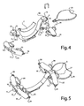
- the tubular frame 30 of the watercraft 31 is made of two half-shells 32, 33 of C-shaped cross-section, joined to one another at their lateral edges, by means of screws 34 passing through through chambered holes whose chambers are intended to receive the heads of the screws 34 and / or the nuts.
- the tubular frame 30 engages at its ends in cavities provided in the floats 35, 36, the locking being provided by a locking means such as for example one or more screws.
- these floats 35, 36 have on one side a curved shape 37 which extends outwardly from the frame 30 and, on the opposite side to the previous one, a serrated shape 38.
- This serrated shape 38 comprises two notches 39, 40 respectively located on either side of a central portion 41 having the cavity 42 in which engages one end of the tubular frame 30 ( figure 7 ).
- each float In a vertical plane perpendicular to the longitudinal median plane of symmetry of the frame 30, each float is in a slightly flattened oval shape ( figure 6 ).
- the convex shape 37 has two indentations 39 ', 40' located in the extension of the indentations 39, 40.
- the two floats 35, 36 have identical shapes and each further comprise through recesses 41, 42, 43, 44 vertically oriented which each delimit with the rim of the float a gripping handle 41 ', 42', 43 ', 44' .
- the central portion of the tubular frame comprises an upper zone covered by a flexible liner 45 consisting of a shell having in an upright transverse plane an inverted U-shaped section.
- the tubular frame has at least one water passage orifice 46 intended to allow a filling of the frame when it is at least partially immersed.
- the tubular frame 30 comprises two coaxial through holes 47, 48 oriented perpendicular to the longitudinal plane of symmetry of the frame 30. These two bores 47, 48 are intended to ensure the passage of two respective coaxial drive axes 49, 50 ( figure 9 ).
- These two drive shafts 49, 50 are rotatably mounted on a rigid structure 51 housed inside the frame 30.
- levers 52, 53 are intended to be manually actuated by a user according to an alternating tilting movement between an anterior position in which they each engage each other in a corresponding recess 39, 40 of the float 36 at a posterior position. in which they are outside the indentations 39, 40.
- the bent form of the levers 52, 53 is intended to extend as far as possible forward the end of the levers that serve as handles to the user.
- This provides an ergonomic arrangement allowing the user to make the most of the strength of his arms.
- each operating lever 52, 53 is provided with a knob 54, 55 of spherical shape, used as a hand grip.
- the frame 30 comprises two coaxial holes oriented parallel to the holes 47, 48, which are intended to ensure the passage of two respective coaxial drive axes 56, 57 in a similar arrangement to that shown figure 9 .
- the attachment of the flippers on the drive shafts 56, 57 is performed by screwing, by means of fixing means allowing adjustment of the orientation of the flippers.
- the two drive shafts 49, 50 - 56, 57 located on the same side of the longitudinal plane of symmetry of the frame 30 are coupled to each other by a transmission mechanism of conventional type.
- this mechanism involves a transmission by cables and pulleys.
- the rigid structure 51 comprises a P beam having a bent shape corresponding to the bent form of the frame 30, here a substantially trapezoidal shape open at the large base.
- This beam P carries, at each of the pairs of holes 47, 48, a transverse axis 60 which extends coaxially with the drilling torques 47, 48, on either side of the beam P.
- the ends of this axis 60 which protrude from either side of the beam P constitute trunnions on which engage two respective tubular drive shafts 49, 50 each carrying inside the frame 30 a double drum T1, T2 - T3, T4 on which are fixed and wind the ends of two cables C1, C2 - C1 ', C2'.
- tubular drive shafts 49, 50 - 56, 57 are secured at their ends which emerge from the frame 30 respectively to the actuating levers 52, 53 and the fins 58, 59 via a cylindrical hub 61 , 62 - 61 ', 62' for example of plastic.
- the two pairs of cables C1, C'1 - C2, C'2 (one pair per side of the beam P) are guided by two pairs of pairs of rollers PC1, PC2 respectively disposed at of the angular region of the trapezoidal shape of the beam P.
- the figure 10 shows a pair of pairs of PC1 pebbles.
- rollers 65, 66 - 67, 68 of each pair of pairs of rollers PC1, PC2 are pivotally mounted about a transverse axis 70 passing through the beam P and extending on both sides thereof to constitute two pins.
- the tilting of a lever 52, 53 in one direction causes the rotation of a corresponding first drum T1, T2 and consequently the winding of one of the cables C1 of this drum T1, T2 and the unwinding of the second cable C2 of the drum T1, T2.
- the winding of the first cable C1 generates on the second drum T3, T4 associated with the palm 58, 59, located on the same side, a running of this cable C1 with a rotation drive of the second drum T3, T4 and corresponding palm 58, 59.
- the second cable C2 then undergoes a winding on the second drum T3, T4 and unwinding on the first drum. Tilting in the opposite direction of the lever 52, 53 will cause an inverse action of the previous one with rotation in the opposite direction of the fin 58, 59.
- the flippers can be directly actuated by the user by means of straight levers 70, 71 equipped with handles directly fixed to the hub 61 ', 62' serving for fixing the fins 58, 59.
- the beam P may have at least partially the shape of a plate provided with fastening means engaging between the two half-shells 32, 33, all of this plate and its equipment (cables / axes / drums / rollers ...) constituting a cassette easily mountable or removable either to facilitate the maintenance of the machine or even to change its configuration.
- This saddle can be specially designed for the disabled.
- the frame 30 may be equipped with a crutch and / or bearing means to ensure the stability of the machine on the ground and / or its possible movement on the ground.
Landscapes
- Chemical & Material Sciences (AREA)
- Engineering & Computer Science (AREA)
- Combustion & Propulsion (AREA)
- Mechanical Engineering (AREA)
- Ocean & Marine Engineering (AREA)
- Health & Medical Sciences (AREA)
- General Health & Medical Sciences (AREA)
- Physical Education & Sports Medicine (AREA)
- Motorcycle And Bicycle Frame (AREA)
- Rehabilitation Tools (AREA)
- Automatic Cycles, And Cycles In General (AREA)
- Other Liquid Machine Or Engine Such As Wave Power Use (AREA)
Claims (22)
- Nautisches Gerät, durch menschliche Kraft angetrieben, bestehend aus:- einem starren Rahmen (30), der einen konkaven Teil abgrenzt- zwei starren länglichen Schwimmern (11, 12), die beziehungsweise auf die zwei Enden des Rahmens befestigt sind, und sich quer über den Rahmen ausdehnen, um einem Benutzer einen Griff oder eine Unterstützung für seine Hände anzubieten, und- einem Sitz (7), der den Benutzer stützt, rittlings auf dem besagten konkaven Teil zu sitzen, gekennzeichnet dadurch, dass der besagte Rahmen röhrenförmig ist, und in seinem niedrigereren Teil wenigstens eine Wasserzugangs-Mündung (8, 9, 10) hat, und in seinem höheren Teil wenigstens eine Luft- oder Abzugs-Mündung (E1, E2) hat, sodass wenn das Gerät sich im Wasser befindet, der Rahmen sich teilweise mit Wasser füllt, das als Ballast dient.
- Nautisches Gerät nach Anspruch 1,
gekennzeichnet dadurch, dass die oben genannte Mündung (E1, E2) mit einem Verschluss (01, 02) ausgestattet ist, um dem Benutzer zu erlauben, die Wasser-Menge innerhalb des Rahmens zu kontrollieren. - Nautisches Gerät nach einer der Ansprüche 1 und 2,
gekennzeichnet dadurch, dass der Rahmen mit einer Antriebs-Möglichkeit ausgestattet ist, die die Rotationsbewegungen des Rahmens nutzt. - Nautisches Gerät nach Anspruch 3,
gekennzeichnet dadurch, dass die oben genannte Antriebs-Möglichkeit aus einer flexiblen verformbaren Flosse (23) besteht, die ungefähr auf Mitte-Höhe des Pfosten des Rahmens befestigt ist, und sich in Richtung der Aussenseite des Rahmens erstreckt. - Nautisches Gerät nach Anspruch 4,
gekennzeichnet dadurch, dass die oben genannte Flosse (23) sich in einem durch die Drehachse (R) des Rahmens, oder sich in der Umgebung der besagten Achse, erstreckt. - Nautisches Gerät nach einer der Ansprüche 4 und 5,
gekennzeichnet dadurch, dass die oben genannte Flosse (23), eine herzförmige Form hat. - Nautisches Gerät nach einer der Ansprüche 4 und 5,
gekennzeichnet dadurch, dass die Pfosten des oben genannten Rahmens mit Mitteln ausgestattet sind, die einen abnehmbaren Zusammenbau der Flosse (23) erlauben. - Nautisches Gerät nach einer der vorhergehenden Ansprüche,
gekennzeichnet dadurch, dass der zentrale Teil des vorher erwähnten Rahmens eine Zone enthält, die mit einem flexiblen Futter (7) in der Form von einer halbzylindrischen Schale bedeckt ist, die als Sitz dient. - Nautisches Gerät nach Anspruch 8,
gekennzeichnet dadurch, dass das besagte Futter (7), aus Geschlossenzellkunststoff besteht. - Nautisches Gerät nach einer der vorhergehenden Ansprüche,
gekennzeichnet dadurch, dass der oben genannte Rahmen aus einem leichten Material wie Kunstsoff besteht. - Nautisches Gerät nach einer der Ansprüche 1, 2, 8, 9 und 10,
gekennzeichnet dadurch, dass es am hinteren Teil des Rahmens (30) wenigstens eine rotierend-montierte Flosse hat, am vorderen Teil des Rahmens (30) wenigstens einen rotierend-montierten Betätigungshebel (52, 53) hat, sowie ein Übertragungsmittel, das das Schlagen der Flosse (58, 59) unter der Wirkung einer wechselnden Kippbewegung der(s) Antriebsshebel(s) (52, 53) ermöglicht. - Nautisches Gerät nach Anspruch 11,
gekennzeichnet dadurch, dass es auf dem vorderen Teil des Rahmens (30) zwei aufgebaute Hebel (52, 53) hat, und dass das Schlagen der Flosse (58, 59) durch eine wechselnde Kippbewegung der zwei Hebel (52, 53) verursacht wird. - Nautisches Gerät nach Anspruch 11,
gekennzeichnet dadurch, dass es am hinteren Teil des Rahmens (30) zwei rotierend-montierte Flossen (58, 59) hat, sowie am vorderen Teil des Rahmens (30) zwei aufgebaute Betätigungshebel (52, 53) hat, wobei jeder Hebel (52, 53) an einer entsprechenden Flosse (58, 59) durch ein unabhängiges Übertragungsmittel gekoppelt ist. - Nautisches Gerät nach einer der Ansprüche 11 bis 13,
gekennzeichnet dadurch, dass das oben genannte Übertragungsmittel von Typ Kabeln/Trommeln und Verweisrollen ist. - Nautisches Gerät nach einer der Ansprüche 11 bis 14,
gekennzeichnet dadurch, dass die oben genannte Flossen (58, 59) und Hebel (52, 53), auf einer starren Struktur (51) rotierend aufgebaut sind, die sich innerhalb des Rahmens (30) befindet. - Nautisches Gerät nach einer der Ansprüche 11 bis 15,
gekennzeichnet dadurch, dass es einen zusätzlichen Betätigungshebel (70, 71) hat, der mit der(n) oben genannten Flosse(n) (58, 59) verbunden ist. - Nautisches Gerät nach Anspruch 15,
gekennzeichnet dadurch, dass die oben genannte starre Struktur (51) das oben genannte Übertragungsmittel trägt, und durch ein abnehmbares Verbindungsmittel zum Rahmen fixiert ist, damit die besagte starre Struktur (51), sowohl ihre Ausstattungen, wie eine Kassette zusammen- und aufeinandergebaut werden können. - Nautisches Gerät nach einer der Ansprüche 11 bis 17,
gekennzeichnet dadurch, dass der röhrenförmige Rahmen (30) aus zwei Halb-Schalen (32, 33) besteht, welche an ihren seitlichen Rändern zusammengebaut werden können, wobei sich die oben genannte starre Struktur (51) angesichts ihrer Besfestigung an den Rahmen zwischen zwei seitlichen Rändern befindet. - Nautisches Gerät nach einer der Ansprüche 11 bis 18,
gekennzeichnet dadurch, dass die oben genannte Betätigungshebel (52, 53) eine verbogene Form haben, und sich in den Einrückungen (39, 40) der oben genannten Flossen. - Nautisches Gerät nach einer der Ansprüche 11 bis 19,
gekennzeichnet dadurch, dass das Übertragungsmittel eine ausrückbare Verbindung hat, die es ermöglicht, die Bewegung der(s) Hebel(s) angesichts der Bewegung der Flossen (58, 59) zu regulieren. - Nautisches Gerät selon eine der vorhergehenden Ansprüche,
gekennzeichnet dadurch, dass der Rahmen (30) mit einer faltbaren Krücke ausgestattet ist, und/oder von Rollmitteln, die die Stabilität des Geräts am Boden und/oder seiner möglichen Reisen auf dem Boden gewährleisten. - Nautisches Gerät nach einer der Ansprüch 11 bis 21,
gekennzeichnet dadurch, dass die Enden des Rahmens (30) sich in den Hohlräumen der Schwimmer (35, 36) befinden.
Applications Claiming Priority (2)
| Application Number | Priority Date | Filing Date | Title |
|---|---|---|---|
| FR0704644A FR2918035B1 (fr) | 2007-06-28 | 2007-06-28 | Engin nautique propulsable par la force humaine |
| PCT/FR2008/000940 WO2009022070A2 (fr) | 2007-06-28 | 2008-06-26 | Engin nautique propulsable par la force humaine |
Publications (2)
| Publication Number | Publication Date |
|---|---|
| EP2158123A2 EP2158123A2 (de) | 2010-03-03 |
| EP2158123B1 true EP2158123B1 (de) | 2013-02-27 |
Family
ID=39052442
Family Applications (1)
| Application Number | Title | Priority Date | Filing Date |
|---|---|---|---|
| EP08827265A Not-in-force EP2158123B1 (de) | 2007-06-28 | 2008-06-26 | Mittels menschlicher kraft antreibbares wasserfahrzeug |
Country Status (4)
| Country | Link |
|---|---|
| US (1) | US20100210158A1 (de) |
| EP (1) | EP2158123B1 (de) |
| FR (1) | FR2918035B1 (de) |
| WO (1) | WO2009022070A2 (de) |
Families Citing this family (2)
| Publication number | Priority date | Publication date | Assignee | Title |
|---|---|---|---|---|
| US9782011B2 (en) * | 2012-06-23 | 2017-10-10 | Swimways Corporation | Water toy |
| US9422038B2 (en) * | 2014-06-27 | 2016-08-23 | Christopher Morgan Rowden | Submersible personal flotation device |
Family Cites Families (8)
| Publication number | Priority date | Publication date | Assignee | Title |
|---|---|---|---|---|
| FR2453774A1 (fr) * | 1979-04-09 | 1980-11-07 | Marjanovic Dragoljub | Legere embarcation nautique, dont la propulsion s'effectue par oscilations longitudinales |
| DE3121328A1 (de) * | 1981-05-29 | 1982-12-16 | Schneider, Gerhard, 7800 Freiburg | "wassersportgeraet" |
| FR2609681B1 (fr) * | 1986-12-31 | 1989-11-10 | Guillouroux Jean | Engin flottant a propulsion par pedales et palmes, l'utilisateur etant semi-immerge |
| NO175358C (no) * | 1991-09-09 | 1994-10-05 | Svein Olsen | Båtskrog |
| US6808434B1 (en) * | 2003-09-08 | 2004-10-26 | Gary T. Park | Buoyant chair and table ensemble |
| US20060057906A1 (en) * | 2004-09-10 | 2006-03-16 | Rong-Jyh Song | Inflatable floating device |
| FR2885113B1 (fr) | 2005-04-27 | 2008-11-14 | Yves Coffournic | Engin nautique a propulsion par la force humaine. |
| US7025418B1 (en) * | 2005-07-01 | 2006-04-11 | Mike Hackal | Positionable floating chair |
-
2007
- 2007-06-28 FR FR0704644A patent/FR2918035B1/fr not_active Expired - Fee Related
-
2008
- 2008-06-26 EP EP08827265A patent/EP2158123B1/de not_active Not-in-force
- 2008-06-26 US US12/666,857 patent/US20100210158A1/en not_active Abandoned
- 2008-06-26 WO PCT/FR2008/000940 patent/WO2009022070A2/fr not_active Ceased
Also Published As
| Publication number | Publication date |
|---|---|
| FR2918035B1 (fr) | 2009-12-04 |
| EP2158123A2 (de) | 2010-03-03 |
| WO2009022070A3 (fr) | 2009-06-04 |
| WO2009022070A2 (fr) | 2009-02-19 |
| US20100210158A1 (en) | 2010-08-19 |
| FR2918035A1 (fr) | 2009-01-02 |
Similar Documents
| Publication | Publication Date | Title |
|---|---|---|
| WO2020254749A1 (fr) | Équipement d'exercice physique notamment pour la méthode pilates | |
| EP2158123B1 (de) | Mittels menschlicher kraft antreibbares wasserfahrzeug | |
| FR2521442A1 (fr) | Poupee animee | |
| WO2022238125A1 (fr) | Dispositif pour la réalisation d'exercices sportifs | |
| KR20090026423A (ko) | 수상이동기구 | |
| FR2590538A1 (fr) | Appareil d'entrainement d'une charge en rotation par pedalage vers l'avant en position horizontale, applicable plus particulierement aux bicyclettes | |
| FR2927001A1 (fr) | Dispositif d'adaptation sur surface porteuse unique tel qu'un snow-board pour elaboration d'un engin de glisse sur neige a propulsion eolienne avec siege et palonnier pourvu de footstraps | |
| EP1874620A1 (de) | Wasserfahrzeug mit antrieb durch menschenkraft | |
| EP1274622B1 (de) | Wasserfahrzeug, welches durch ein pedalbetriebenes zweischaufelgerät angetrieben wird | |
| EP3251729B1 (de) | Struktur für körperliche übungen der unteren gliedmassen in einem flüssigen milieu | |
| FR3021623A1 (fr) | Velo nautique propulse par un jet d'eau | |
| FR2735439A1 (fr) | Appareil de deplacement a patins mobiles et bras pivotants | |
| FR2550159A1 (fr) | Engin flottant individuel, mu par son pilote, a usage sportif ou de loisir | |
| FR2614002A1 (fr) | Jouet mini-kart auto-propulseur | |
| FR3069521B1 (fr) | Engin nautique propulse | |
| FR2474431A1 (en) | Lever propelled recreational vehicle - has low chassis carrying sliding seat and front wheel axle connected by sloping spindle for steering | |
| FR2798072A1 (fr) | Perfectionnement pour vehicule glissant sur neige | |
| FR2744640A1 (fr) | Dispositif d'aide a la nage | |
| FR2787413A1 (fr) | Dispositif de propulsion de cycle a l'aide des bras du conducteur | |
| FR3156114A1 (fr) | Bâton pour se déplacer sur l'eau | |
| FR3156113A1 (fr) | Engin nautique pour se déplacer sur l'eau | |
| WO1992009348A1 (fr) | Dispositif de jeu aquatique | |
| CA2127159C (fr) | Bicyclette sur glace | |
| WO2003011686A1 (fr) | Catamaran propulse par une helice actionnee par mouvements alternatifs | |
| FR2719493A1 (fr) | Appareil pour effectuer des exercices physiques. |
Legal Events
| Date | Code | Title | Description |
|---|---|---|---|
| PUAI | Public reference made under article 153(3) epc to a published international application that has entered the european phase |
Free format text: ORIGINAL CODE: 0009012 |
|
| 17P | Request for examination filed |
Effective date: 20091215 |
|
| AK | Designated contracting states |
Kind code of ref document: A2 Designated state(s): AT BE BG CH CY CZ DE DK EE ES FI FR GB GR HR HU IE IS IT LI LT LU LV MC MT NL NO PL PT RO SE SI SK TR |
|
| AX | Request for extension of the european patent |
Extension state: AL BA MK RS |
|
| 17Q | First examination report despatched |
Effective date: 20100903 |
|
| REG | Reference to a national code |
Ref country code: DE Ref legal event code: R079 Ref document number: 602008022572 Country of ref document: DE Free format text: PREVIOUS MAIN CLASS: B63H0001360000 Ipc: A63B0035100000 |
|
| GRAP | Despatch of communication of intention to grant a patent |
Free format text: ORIGINAL CODE: EPIDOSNIGR1 |
|
| RIC1 | Information provided on ipc code assigned before grant |
Ipc: B63H 16/08 20060101ALI20120330BHEP Ipc: B63H 1/36 20060101ALI20120330BHEP Ipc: B63B 35/74 20060101ALI20120330BHEP Ipc: A63B 35/00 20060101ALI20120330BHEP Ipc: B63B 43/06 20060101ALI20120330BHEP Ipc: A63B 35/10 20060101AFI20120330BHEP |
|
| DAX | Request for extension of the european patent (deleted) | ||
| GRAS | Grant fee paid |
Free format text: ORIGINAL CODE: EPIDOSNIGR3 |
|
| GRAA | (expected) grant |
Free format text: ORIGINAL CODE: 0009210 |
|
| AK | Designated contracting states |
Kind code of ref document: B1 Designated state(s): AT BE BG CH CY CZ DE DK EE ES FI FR GB GR HR HU IE IS IT LI LT LU LV MC MT NL NO PL PT RO SE SI SK TR |
|
| REG | Reference to a national code |
Ref country code: GB Ref legal event code: FG4D Free format text: NOT ENGLISH |
|
| REG | Reference to a national code |
Ref country code: CH Ref legal event code: EP |
|
| REG | Reference to a national code |
Ref country code: AT Ref legal event code: REF Ref document number: 598185 Country of ref document: AT Kind code of ref document: T Effective date: 20130315 |
|
| REG | Reference to a national code |
Ref country code: IE Ref legal event code: FG4D Free format text: LANGUAGE OF EP DOCUMENT: FRENCH |
|
| REG | Reference to a national code |
Ref country code: DE Ref legal event code: R096 Ref document number: 602008022572 Country of ref document: DE Effective date: 20130425 |
|
| REG | Reference to a national code |
Ref country code: AT Ref legal event code: MK05 Ref document number: 598185 Country of ref document: AT Kind code of ref document: T Effective date: 20130227 |
|
| REG | Reference to a national code |
Ref country code: LT Ref legal event code: MG4D |
|
| PG25 | Lapsed in a contracting state [announced via postgrant information from national office to epo] |
Ref country code: SE Free format text: LAPSE BECAUSE OF FAILURE TO SUBMIT A TRANSLATION OF THE DESCRIPTION OR TO PAY THE FEE WITHIN THE PRESCRIBED TIME-LIMIT Effective date: 20130227 Ref country code: LT Free format text: LAPSE BECAUSE OF FAILURE TO SUBMIT A TRANSLATION OF THE DESCRIPTION OR TO PAY THE FEE WITHIN THE PRESCRIBED TIME-LIMIT Effective date: 20130227 Ref country code: NO Free format text: LAPSE BECAUSE OF FAILURE TO SUBMIT A TRANSLATION OF THE DESCRIPTION OR TO PAY THE FEE WITHIN THE PRESCRIBED TIME-LIMIT Effective date: 20130527 Ref country code: BG Free format text: LAPSE BECAUSE OF FAILURE TO SUBMIT A TRANSLATION OF THE DESCRIPTION OR TO PAY THE FEE WITHIN THE PRESCRIBED TIME-LIMIT Effective date: 20130527 Ref country code: AT Free format text: LAPSE BECAUSE OF FAILURE TO SUBMIT A TRANSLATION OF THE DESCRIPTION OR TO PAY THE FEE WITHIN THE PRESCRIBED TIME-LIMIT Effective date: 20130227 Ref country code: IS Free format text: LAPSE BECAUSE OF FAILURE TO SUBMIT A TRANSLATION OF THE DESCRIPTION OR TO PAY THE FEE WITHIN THE PRESCRIBED TIME-LIMIT Effective date: 20130627 Ref country code: ES Free format text: LAPSE BECAUSE OF FAILURE TO SUBMIT A TRANSLATION OF THE DESCRIPTION OR TO PAY THE FEE WITHIN THE PRESCRIBED TIME-LIMIT Effective date: 20130607 |
|
| REG | Reference to a national code |
Ref country code: NL Ref legal event code: VDEP Effective date: 20130227 |
|
| PG25 | Lapsed in a contracting state [announced via postgrant information from national office to epo] |
Ref country code: FI Free format text: LAPSE BECAUSE OF FAILURE TO SUBMIT A TRANSLATION OF THE DESCRIPTION OR TO PAY THE FEE WITHIN THE PRESCRIBED TIME-LIMIT Effective date: 20130227 Ref country code: SI Free format text: LAPSE BECAUSE OF FAILURE TO SUBMIT A TRANSLATION OF THE DESCRIPTION OR TO PAY THE FEE WITHIN THE PRESCRIBED TIME-LIMIT Effective date: 20130227 Ref country code: GR Free format text: LAPSE BECAUSE OF FAILURE TO SUBMIT A TRANSLATION OF THE DESCRIPTION OR TO PAY THE FEE WITHIN THE PRESCRIBED TIME-LIMIT Effective date: 20130528 Ref country code: PT Free format text: LAPSE BECAUSE OF FAILURE TO SUBMIT A TRANSLATION OF THE DESCRIPTION OR TO PAY THE FEE WITHIN THE PRESCRIBED TIME-LIMIT Effective date: 20130627 Ref country code: PL Free format text: LAPSE BECAUSE OF FAILURE TO SUBMIT A TRANSLATION OF THE DESCRIPTION OR TO PAY THE FEE WITHIN THE PRESCRIBED TIME-LIMIT Effective date: 20130227 Ref country code: LV Free format text: LAPSE BECAUSE OF FAILURE TO SUBMIT A TRANSLATION OF THE DESCRIPTION OR TO PAY THE FEE WITHIN THE PRESCRIBED TIME-LIMIT Effective date: 20130227 |
|
| PG25 | Lapsed in a contracting state [announced via postgrant information from national office to epo] |
Ref country code: HR Free format text: LAPSE BECAUSE OF FAILURE TO SUBMIT A TRANSLATION OF THE DESCRIPTION OR TO PAY THE FEE WITHIN THE PRESCRIBED TIME-LIMIT Effective date: 20130227 |
|
| PG25 | Lapsed in a contracting state [announced via postgrant information from national office to epo] |
Ref country code: CZ Free format text: LAPSE BECAUSE OF FAILURE TO SUBMIT A TRANSLATION OF THE DESCRIPTION OR TO PAY THE FEE WITHIN THE PRESCRIBED TIME-LIMIT Effective date: 20130227 Ref country code: EE Free format text: LAPSE BECAUSE OF FAILURE TO SUBMIT A TRANSLATION OF THE DESCRIPTION OR TO PAY THE FEE WITHIN THE PRESCRIBED TIME-LIMIT Effective date: 20130227 Ref country code: DK Free format text: LAPSE BECAUSE OF FAILURE TO SUBMIT A TRANSLATION OF THE DESCRIPTION OR TO PAY THE FEE WITHIN THE PRESCRIBED TIME-LIMIT Effective date: 20130227 Ref country code: SK Free format text: LAPSE BECAUSE OF FAILURE TO SUBMIT A TRANSLATION OF THE DESCRIPTION OR TO PAY THE FEE WITHIN THE PRESCRIBED TIME-LIMIT Effective date: 20130227 Ref country code: NL Free format text: LAPSE BECAUSE OF FAILURE TO SUBMIT A TRANSLATION OF THE DESCRIPTION OR TO PAY THE FEE WITHIN THE PRESCRIBED TIME-LIMIT Effective date: 20130227 Ref country code: RO Free format text: LAPSE BECAUSE OF FAILURE TO SUBMIT A TRANSLATION OF THE DESCRIPTION OR TO PAY THE FEE WITHIN THE PRESCRIBED TIME-LIMIT Effective date: 20130227 |
|
| PG25 | Lapsed in a contracting state [announced via postgrant information from national office to epo] |
Ref country code: CY Free format text: LAPSE BECAUSE OF FAILURE TO SUBMIT A TRANSLATION OF THE DESCRIPTION OR TO PAY THE FEE WITHIN THE PRESCRIBED TIME-LIMIT Effective date: 20130227 |
|
| BERE | Be: lapsed |
Owner name: COFFOURNIC, YVES Effective date: 20130630 |
|
| PG25 | Lapsed in a contracting state [announced via postgrant information from national office to epo] |
Ref country code: IT Free format text: LAPSE BECAUSE OF FAILURE TO SUBMIT A TRANSLATION OF THE DESCRIPTION OR TO PAY THE FEE WITHIN THE PRESCRIBED TIME-LIMIT Effective date: 20130227 |
|
| PLBE | No opposition filed within time limit |
Free format text: ORIGINAL CODE: 0009261 |
|
| STAA | Information on the status of an ep patent application or granted ep patent |
Free format text: STATUS: NO OPPOSITION FILED WITHIN TIME LIMIT |
|
| PG25 | Lapsed in a contracting state [announced via postgrant information from national office to epo] |
Ref country code: MC Free format text: LAPSE BECAUSE OF FAILURE TO SUBMIT A TRANSLATION OF THE DESCRIPTION OR TO PAY THE FEE WITHIN THE PRESCRIBED TIME-LIMIT Effective date: 20130227 |
|
| REG | Reference to a national code |
Ref country code: CH Ref legal event code: PL |
|
| 26N | No opposition filed |
Effective date: 20131128 |
|
| GBPC | Gb: european patent ceased through non-payment of renewal fee |
Effective date: 20130626 |
|
| REG | Reference to a national code |
Ref country code: DE Ref legal event code: R097 Ref document number: 602008022572 Country of ref document: DE Effective date: 20131128 |
|
| REG | Reference to a national code |
Ref country code: IE Ref legal event code: MM4A |
|
| REG | Reference to a national code |
Ref country code: FR Ref legal event code: ST Effective date: 20140228 |
|
| PG25 | Lapsed in a contracting state [announced via postgrant information from national office to epo] |
Ref country code: BE Free format text: LAPSE BECAUSE OF NON-PAYMENT OF DUE FEES Effective date: 20130630 |
|
| REG | Reference to a national code |
Ref country code: DE Ref legal event code: R119 Ref document number: 602008022572 Country of ref document: DE Effective date: 20140101 |
|
| PG25 | Lapsed in a contracting state [announced via postgrant information from national office to epo] |
Ref country code: IE Free format text: LAPSE BECAUSE OF NON-PAYMENT OF DUE FEES Effective date: 20130626 Ref country code: LI Free format text: LAPSE BECAUSE OF NON-PAYMENT OF DUE FEES Effective date: 20130630 Ref country code: DE Free format text: LAPSE BECAUSE OF NON-PAYMENT OF DUE FEES Effective date: 20140101 Ref country code: CH Free format text: LAPSE BECAUSE OF NON-PAYMENT OF DUE FEES Effective date: 20130630 Ref country code: GB Free format text: LAPSE BECAUSE OF NON-PAYMENT OF DUE FEES Effective date: 20130626 |
|
| PG25 | Lapsed in a contracting state [announced via postgrant information from national office to epo] |
Ref country code: FR Free format text: LAPSE BECAUSE OF NON-PAYMENT OF DUE FEES Effective date: 20130701 |
|
| PG25 | Lapsed in a contracting state [announced via postgrant information from national office to epo] |
Ref country code: MT Free format text: LAPSE BECAUSE OF FAILURE TO SUBMIT A TRANSLATION OF THE DESCRIPTION OR TO PAY THE FEE WITHIN THE PRESCRIBED TIME-LIMIT Effective date: 20130227 |
|
| PG25 | Lapsed in a contracting state [announced via postgrant information from national office to epo] |
Ref country code: TR Free format text: LAPSE BECAUSE OF FAILURE TO SUBMIT A TRANSLATION OF THE DESCRIPTION OR TO PAY THE FEE WITHIN THE PRESCRIBED TIME-LIMIT Effective date: 20130227 |
|
| PG25 | Lapsed in a contracting state [announced via postgrant information from national office to epo] |
Ref country code: LU Free format text: LAPSE BECAUSE OF NON-PAYMENT OF DUE FEES Effective date: 20130626 Ref country code: HU Free format text: LAPSE BECAUSE OF FAILURE TO SUBMIT A TRANSLATION OF THE DESCRIPTION OR TO PAY THE FEE WITHIN THE PRESCRIBED TIME-LIMIT; INVALID AB INITIO Effective date: 20080626 |