EP2158805B1 - Outil de découpe de végétaux - Google Patents
Outil de découpe de végétaux Download PDFInfo
- Publication number
- EP2158805B1 EP2158805B1 EP08105135A EP08105135A EP2158805B1 EP 2158805 B1 EP2158805 B1 EP 2158805B1 EP 08105135 A EP08105135 A EP 08105135A EP 08105135 A EP08105135 A EP 08105135A EP 2158805 B1 EP2158805 B1 EP 2158805B1
- Authority
- EP
- European Patent Office
- Prior art keywords
- link
- cutting tool
- cutter member
- crank
- motor
- Prior art date
- Legal status (The legal status is an assumption and is not a legal conclusion. Google has not performed a legal analysis and makes no representation as to the accuracy of the status listed.)
- Expired - Fee Related
Links
Images


Classifications
-
- B—PERFORMING OPERATIONS; TRANSPORTING
- B26—HAND CUTTING TOOLS; CUTTING; SEVERING
- B26B—HAND-HELD CUTTING TOOLS NOT OTHERWISE PROVIDED FOR
- B26B13/00—Hand shears; Scissors
- B26B13/22—Hand shears; Scissors combined with auxiliary implements, e.g. with cigar cutter, with manicure instrument
-
- A—HUMAN NECESSITIES
- A01—AGRICULTURE; FORESTRY; ANIMAL HUSBANDRY; HUNTING; TRAPPING; FISHING
- A01G—HORTICULTURE; CULTIVATION OF VEGETABLES, FLOWERS, RICE, FRUIT, VINES, HOPS OR SEAWEED; FORESTRY; WATERING
- A01G3/00—Cutting implements specially adapted for horticultural purposes; Delimbing standing trees
- A01G3/02—Secateurs; Flower or fruit shears
- A01G3/033—Secateurs; Flower or fruit shears having motor-driven blades
-
- A—HUMAN NECESSITIES
- A01—AGRICULTURE; FORESTRY; ANIMAL HUSBANDRY; HUNTING; TRAPPING; FISHING
- A01G—HORTICULTURE; CULTIVATION OF VEGETABLES, FLOWERS, RICE, FRUIT, VINES, HOPS OR SEAWEED; FORESTRY; WATERING
- A01G3/00—Cutting implements specially adapted for horticultural purposes; Delimbing standing trees
- A01G3/02—Secateurs; Flower or fruit shears
- A01G3/033—Secateurs; Flower or fruit shears having motor-driven blades
- A01G3/037—Secateurs; Flower or fruit shears having motor-driven blades the driving means being an electric motor
-
- B—PERFORMING OPERATIONS; TRANSPORTING
- B26—HAND CUTTING TOOLS; CUTTING; SEVERING
- B26B—HAND-HELD CUTTING TOOLS NOT OTHERWISE PROVIDED FOR
- B26B15/00—Hand-held shears with motor-driven blades
Definitions
- the present invention relates to a vegetation cutting tool.
- the present invention relates to a powered vegetation cutting tool and more particularly to a linkage mechanism for a powered vegetation cutting tool.
- Vegetation cutting tools such as pruning tools and secateurs are well known for use in cutting plant stems and trees and shrub branches.
- secateur "anvil”, which comprise a single blade that can be moved against a flat surface to cut a stem; "bypass”, which usually comprise a pair of blades (often just one of the blades has a cutting surface) that are operated like a pair of scissors, and which provide a shearing force to cut the stem as the blades are moved passed each other; and "parrot-beak”, which are also operable like a pair of scissors and which comprise a pair of concave blades, between which a stem can be trapped and cut.
- Pruning tools may be manually operated or driven, usually by an electrical motor.
- Powered pruning tools operate to move at least one blade of a pair of blades between an open configuration, in which cutting edges of the moveable blade and a fixed blade are apart, and a closed configuration, in which the cutting edges of the blades abut or just pass one another. If powered cutting action is conducted in response to the actuation of an external user-control in the form of a button or trigger. When the user-control is released, the blades return to the open configuration. Typically, this is achieved by a reduction gearbox driving a partial gear segment on the moving blade.
- EP 803187 A2 describes a set of pruning shears which have two relatively adjustable cutting blades, one of which is secured to the housing of the shears, the other operated by an electric motor.
- the fixed blade is secured with a threaded spindle, a spindle nut and a displacement rod.
- the operation of the electric motor is controlled via a control switch with a pair of switch elements inserted in the electric motor current circuit.
- the spindle nut has a cam guide for control cams associated with the switch elements.
- Electric scissors are also known. However, these devices operate by reciprocating the blades repeatedly to perform a sequence of cutting and opening movements. Unlike pruning tools, the scissor blades operate in a continuous manner without the need for a stop/reverse function.
- US 2005/0160606 A1 describes a pair of electric scissors comprised of a casing, a motor, a driving disk, a crank, and a cutting unit with a pair of blades.
- the driving disk, crank and blades of the cutting unit are connected pivotally and eccentrically.
- the motor is installed with a speed change means so that the rotation speed of the motor, and thus the rotary shaft, can be reduced to provide a higher torsion force for cutting tougher objects.
- the present invention seeks to overcome at least some of these disadvantages.
- WO89/03171 describes a vegetation cutting tool in accordance with the preamble to claim 1.
- the present invention provides a vegetation cutting tool as claimed in Claim 1.
- the transmission means further comprises a reduction gear assembly, including an output bearing, which is drivable by the motor, and in which the crank is drivable by the gear assembly.
- a reduction gear assembly including an output bearing, which is drivable by the motor, and in which the crank is drivable by the gear assembly.
- the first cutter member comprises a cutting surface having a sharpened leading edge.
- the first cutter member is moveable in a plane parallel and adjacent to the plane in which the second cutter member lies, and is arranged to be slidably drivable over a surface of the second cutter member.
- first and second cutter members are arranged such that the cutting surface of the first cutter member is drivable against a cutting surface of the second cutter member.
- the engagement means comprises a tab formed on the first cutter member.
- the Link comprises a slot which is operatively engageable with the tab.
- the vegetation cutting tool comprises a user-control for activating the motor.
- the user-control provides a non-continuous activation of the motor, in use.
- the user-control is moveable between first and second positions to effect movement of the first moveable member between the first and second angular positions, and wherein release of the user-control, in use, causes the first cutter member to move to the first angular position
- the user-control comprises a trigger.
- the release of the trigger in use, causes the first cutter member to return to the first angular position.
- the crank comprises a crank body and crank arm.
- the crank body is operatively coupled to an output shaft of the motor or reduction gearbox.
- the crank is operatively connected to the link such that the connection is substantially in-line with the gear assembly output bearing.
- the motor is a direct current motor.
- the vegetation cutting tool is battery-powered.
- the battery is rechargeable; more preferably, the battery is a lithium-ion battery.
- the vegetation cutting tool further comprises one or more limit switches.
- At least one limit switch breaks the supply of power to the motor when the at least one of said cutter members has moved from said first angular position to said second angular position, in operation.
- the one or more limit switches enable a short circuit across the motor terminals when the at least one of said cutter members has moved from said first angular position to said second angular position, in use.
- the one or more limit switches activate relays to make or break the motor electrical connections, in use.
- two relays are activated, in use.
- the two relays are formed as a single twin-relay component.
- the gearbox is an epicyclic unit mounted coaxially to the motor.
- the gearbox has a reduction ratio of between 300:1 and 700: 1; preferably, between 400:1 and 600:1; more preferably about 516:1.
- the reduction is carried out by means of a four stage assembly.
- the first cutter member is pivotably mounted with respect to the second cutter member by a pin and pivot bush.
- the first cutter member is demountable.
- the first cutter member is demountable by means of removal of the pin and pivot bush.
- the link further comprises an integral link tab, formed therewith, and the link tab is moveable within the channel in the linkage mounting moulding.
- the link comprises a link aperture at an operatively upper end which is rotatably engaged with the crank to provide a mechanical engagement between the link and crank.
- the cutting head and transmission means comprises a single working unit.
- the pin is a screw or threaded fixing, such as a bolt.
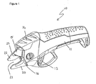
- a vegetation cutting tool in the form of a pruner 10 generally of the bypass type and comprising an elongate handle 11 including a user-control in the form of a trigger 13.
- Handle 11 further includes a cutting head 14 located at a front end of handle 11, the cutting head 14 comprising a moveable cutter member 15 and a fixed cutting head element in the form of a plate 16.
- Plate 16 comprises a fixed cutting member 20 and a vegetation guide 22 forming a vegetation-receiving channel 21 therebetween.
- Moveable cutter member 15 includes a sharpened leading or cutting edge 23 and is pivotally drivable, in use, between retracted and extended positions by a motor (24 in Figure 2 ).
- a motor 24 in Figure 2
- moveable and fixed cutter members 15,20 are operatively spaced, and the sharpened leading edge is retracted and protected by vegetation guide 22, and vegetation-receiving channel 21 is open.
- the action of driving moveable cutter member 15 towards the fixed cutter member 20 and particularly its unsharpened leading edge 54 provides a shearing action therebetween in the manner of a bypass-type pruner. That shearing action can be used to cut any vegetation which has been located within the vegetation-receiving channel 21.
- the action of driving the moveable cutter member 15 towards the fixed cutter member 20 provides a simple cutting force therebetween, in which a sharpened leading edge of the moveable cutter member 15 forces the article to be cut against the fixed cutter member 20 to thereby cut the article in the manner of a anvil-type pruner.
- the fixed cutter member 20 is not moveable.
- second cutter member 20 is reciprocally drivable relative to the moveable cutter member 15.
- Figure 2 shows the assembled mechanism of the pruner 10 with the moveable cutter member 15 in a retracted position, leaving vegetation-receiving channel 21 open for receipt of vegetation.
- the mechanism includes a motor 24 connected coaxially to a gearbox unit 25.
- the gearbox unit 25 is suitably a four-stage epicyclic gearbox (see Figure 6 ) which provides a reduction in the motor speed in the ratio of around 516:1.
- a crank 30 is rotatably attached to the gearbox output shaft (obscured), and comprises a crank body 31 and crank arm 32. Crank body 31 is connected to the output shaft of the gearbox unit 25.
- crank arm 32 is orientated to extend backwards towards the gearbox at its outer end, such that a point of connection with the cutting head is substantially in line with an end bearing 55 of the gearbox. As a result, any overhung bearing loads on the output shaft are reduced.
- moveable cutter member 15 includes an aperture 39 through which a pivot bush 41 is inserted and secured by pin in the form of a bolt 42 to mount moveable cutter member 15 pivotally upon plate 16 about a pivot point defined by the outer surface of pivot bush 41.
- Moveable cutter member 15 5 includes a tab 40.
- the mechanism further includes a link 34 which links crank arm 32 to the moveable cutting member 15.
- Link 34 includes a link aperture 52 at an operatively upper end ( Figure 5 ) which rotatably engages with crank arm 32 to provide a mechanical engagement between the link 34 and crank 30.
- the link 34 is retained on the crank arm 32 by a threaded bolt, or screw 53.
- the link 34 also includes a slot 35 provided at an operatively lower end of link 34 which operatively engages with the moveable cutter member 15 through tab 40.
- the linkage assembly is formed as a 'self-contained' unit around a linkage mounting moulding 60.
- Plate 16 is securely fixed to the linkage mounting moulding 60 by suitable securing means, for example a screw 61.
- moveable blade 15 is rotatably mounted on plate 16 by pivot bush 41 and pin 42.
- pin 42 passes through moveable blade 15 and plate 16 and fastens into captive nut 62 which is retained between the linkage mounting moulding 60 and plate 16.
- the gear assembly, incorporating the output bearing 55 is housed within the linkage mounting moulding 60 to provide the 'self-contained' unit.
- the linkage mounting moulding 60 includes a groove or channel 37 in which a portion of the link 34 is moveable, and which restricts the range of movement of the link 34, during normal operation.
- link 34 comprises a protrusion or link tab 36 which is moveable within channel 37 of the linkage mounting moulding 60.
- crank 30 in use, rotation of crank 30 by means of motor 24 causes link 34 to move in an upwards direction (in terms of the orientation shown in the Figures).
- the link 34 acts on the moveable cutter member 15, through the slot-tab engagement, to cause moveable cutter member 15 to rotate about the pivot point.
- the offset formed between crank body 31 and crank arm 32 has the effect that its engagement with the link 34 is substantially in-line with the gearbox output shaft bearing 55. This arrangement reduces the occurrence of bending loads on the gearbox output shaft and removes the need for additional load-carrying bearings.
- Moveable cutter member 15 also includes profiles 44,44' which, in use, sequentially actuate a pair of electrical limit switches 45,50 located on or adjacent plate 16, in response to the moveable cutter member being moved between retracted and extended positions.
- the profiles act upon electrical limit switches 45,50 to indicate to the pruner control electronics (omitted for clarity) that the cutter member has reached the respective fully retracted or extended position.
- This causes the power supplied to the motor to be switched off, suitably, by means of electrical relays (not shown).
- a short-circuit is also applied to the motor terminals to provide a rapid braking effect upon the cutter member.
- crank 30 A limit to the angular movement of crank 30 is provided by mechanical means, in this case by contact between the crank and a linkage mounting moulding of the pruner (not shown).
- movement of the link 34, and thus the crank 30 and moveable cutter member 15, is restricted due to the constraints imposed by the operative engagement of the integral link tab 36 of link 34 within channel 37 provided in the linkage mounting moulding ( Figure 6 )
- FIG. 3 there is shown a view of the mechanism in which the moveable cutter member 15 is in an extended position.
- activation of trigger 13 has caused the motor 24 to be energised to rotate the crank arm 30 through an angle of around 75 to 80 degrees.
- the closed limit switch 45 has been actuated by engagement with profile 44' of cutter member 15 and power to the motor has been switched off.
- the motor terminals have been short-circuited to achieve a braking effect.
- the mechanism remains in this closed configuration until trigger 13 is released by the user.
- crank 30 is also restricted by further mechanical means, such as by contact between the moving blade and the linkage mounting moulding of the pruner adjacent to the tab 40 (not shown).
- Alternative assemblies such as engagement of a portion of link 34 and the linkage mounting moulding surface around the gearbox output bearing 55 can be used.
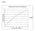
- the linkage mechanism described provides a mechanical advantage defined by the ratio between crank arm 32 angular rotation and moving blade (moveable cutter member) angular rotation.
- This mechanical advantage is variable throughout the cutting stroke of the moveable cutter member 15.
- a particular advantage of this arrangement is that the cutting force available to a branch of a particular diameter is then the same regardless of whether the branch is engaged by the moveable cutter member close to its pivot point (and therefore at a smaller moveable cutter member angular movement) or at its tip (and therefore at a greater moveable cutter member angular movement).
- a further advantage of the described linkage mechanism is that the moveable cutter member 15 is easily demountable for sharpening or replacement. As shown in Figure 4 , this is achieved by removing the bolt 42 and pivot bush 41 whereupon the moveable cutter member can be demounted from the tool by removing its tab 40 from the slot 35 at the lower end of link 34.
- the operative engagement of link tab 36 within channel 37 provided in the linkage mounting moulding ensures that the link 34 is appropriately retained in its correct position.
- the linkage mechanism provides a low cost, compact and mechanically efficient design. It is especially suitable for application in portable battery-powered tools, such as pruners, in which the mechanism forms a self-contained working element formed around and located to a linkage mounting moulding within the moulding of the case in which the pruner is housed.
- the pruner is ideally powered by one or more lithium-ion cells 51, due to their relative lightness in weight.
- the high efficiency of the mechanism means that the pruner tool can even be used with a single battery cell for cutting material up to 14mm in diameter.
- a suitable battery cell of 3.6 Volt, 1.3 Ah could achieve around 400 cuts of 12mm diameter vegetation before recharging was required.
- control electronics for the motor and or limit switch operations are also utilised to provide lithium-ion battery monitoring and controlling functions. For example, it may be desired to disable operation of the motor in the event that the battery becomes discharged below a pre-selected voltage or its temperature exceeds a predefined limit.
Landscapes
- Life Sciences & Earth Sciences (AREA)
- Forests & Forestry (AREA)
- Engineering & Computer Science (AREA)
- Mechanical Engineering (AREA)
- Biodiversity & Conservation Biology (AREA)
- Ecology (AREA)
- Environmental Sciences (AREA)
- Scissors And Nippers (AREA)
- Harvester Elements (AREA)
- Transmission Devices (AREA)
Claims (12)
- Outil de découpe de végétaux comprenant une tête de coupe (14), un moteur (24) et des moyens de transmission pouvant être entraînés par le moteur ;
la tête de coupe (14) comprenant des premier et second éléments tranchants ayant des surfaces de coupe (23, 54) respectives, le premier élément tranchant (15) étant fixé de façon pivotante par rapport au second élément tranchant (20) ;
au moins le premier élément tranchant (15) pouvant être entraîné par les moyens de transmission entre une première position angulaire par rapport au second élément tranchant (20), où un espace est formé entre les surfaces de coupe (23, 54) respectives, et une seconde position angulaire par rapport au second élément tranchant (20), où l'espace entre les surfaces de coupe (23, 54) respectives est fermé ; et
les moyens de transmission (25) comprenant des moyens de mise en prise (40) associés au premier élément tranchant (15) et une manivelle (30) pouvant être entraînée entre des première et seconde positions angulaires de manivelle définies correspondant aux première et seconde positions angulaires, la manivelle (30) étant couplée en fonctionnement aux moyens de mise en prise (40) par une articulation (34) ;
caractérisé en ce que le premier élément tranchant (15) peut être démonté par sortie de prise des moyens de mise en prise (40) hors de l'articulation (34) ; l'articulation (34) est maintenue en place lors du retrait du premier élément tranchant (15) ; et caractérisé en outre en ce que la tête de coupe comprend une moulure de fixation de jonction (60) et en ce que l'articulation (34) est mobile à l'intérieur d'un canal (37) prévu dans la moulure de fixation de jonction (60), pour lui permettre de conserver sa position par rapport à la moulure de fixation de jonction (60). - Outil de découpe de végétaux selon la revendication 1, dans lequel l'articulation (34) comprend en outre une patte d'articulation (36) intégrée, formée avec elle, la patte d'articulation (36) étant mobile à l'intérieur du canal (37) dans la moulure de fixation de jonction (60).
- Outil de découpe de végétaux selon la revendication 1 ou 2, dans lequel l'articulation (34) comprend une ouverture d'articulation (52) placée en fonctionnement au niveau d'une extrémité supérieure qui est mise en prise de façon à pouvoir tourner avec la manivelle (30) pour permettre une mise en prise mécanique entre l'articulation (34) et la manivelle (30).
- Outil de découpe de végétaux selon l'une quelconque des revendications 1 à 3, dans lequel les moyens de transmission comprennent en outre un ensemble d'engrenage de réduction (25), comprenant un palier de sortie (55) pouvant être entraîné par le moteur et dans lequel la manivelle peut être entraînée par l'ensemble d'engrenage (25).
- Outil de découpe de végétaux selon l'une quelconque des revendications 1 à 4, dans lequel les moyens de mise en prise comprennent une patte (40) formée sur le premier élément tranchant (15).
- Outil de découpe de végétaux selon la revendication 5, dans lequel l'articulation comprend une fente (35) pouvant entrer en prise, en fonctionnement, avec la patte (40).
- Outil de découpe de végétaux selon l'une quelconque des revendications précédentes, comprenant en outre une commande d'utilisateur pour permettre d'activer de façon non continue le moteur (24), dans lequel la commande d'utilisateur peut être déplacée entre des première et seconde positions pour déplacer le premier élément mobile (15) entre les première et seconde positions angulaires, et dans lequel le relâchement de la commande d'utilisateur provoque, en fonctionnement, le déplacement du premier élément tranchant (15) permettant de revenir à la première position angulaire.
- Outil de découpe de végétaux selon l'une quelconque des revendications 4 à 7, dans lequel la manivelle (30) est reliée en fonctionnement à l'articulation (34) de telle sorte que la connexion est sensiblement alignée avec le palier de sortie (55) de l'ensemble d'engrenage.
- Outil de découpe de végétaux selon l'une quelconque des revendications précédentes, dans lequel l'outil de découpe de végétaux comprend en outre un ou plusieurs interrupteurs de fin de course (45, 50) et dans lequel au moins un interrupteur de fin de course (45, 50) bloque l'alimentation en courant du moteur (24) lorsque l'au moins un desdits éléments tranchants (15) est déplacé de ladite première position angulaire dans ladite seconde position angulaire.
- Outil de découpe de végétaux selon l'une quelconque des revendications précédentes, comprenant en outre deux interrupteurs de fin de course (45, 50) donc chacun est associé à un relais pour connecter ou déconnecter les connexions électriques du moteur, dans lequel les relais prennent la forme d'un seul relais jumeau.
- Outil de découpe de végétaux selon l'une quelconque des revendications 4 à 10, dans lequel l'ensemble d'engrenage de réduction (25) est un ensemble d'engrenage de réduction épicyclique fixé coaxialement au moteur.
- Outil de découpe de végétaux selon l'une quelconque des revendications précédentes, dans lequel la tête de coupe (14) et les moyens de transmission comprennent une seule unité de travail.
Priority Applications (3)
| Application Number | Priority Date | Filing Date | Title |
|---|---|---|---|
| EP08105135A EP2158805B1 (fr) | 2008-08-26 | 2008-08-26 | Outil de découpe de végétaux |
| RU2009131994/21A RU2009131994A (ru) | 2008-08-26 | 2009-08-25 | Ручная машина для резки растительного материала |
| US12/547,366 US20100077621A1 (en) | 2008-08-26 | 2009-08-25 | Vegetation cutting tool |
Applications Claiming Priority (1)
| Application Number | Priority Date | Filing Date | Title |
|---|---|---|---|
| EP08105135A EP2158805B1 (fr) | 2008-08-26 | 2008-08-26 | Outil de découpe de végétaux |
Publications (2)
| Publication Number | Publication Date |
|---|---|
| EP2158805A1 EP2158805A1 (fr) | 2010-03-03 |
| EP2158805B1 true EP2158805B1 (fr) | 2011-11-02 |
Family
ID=40260604
Family Applications (1)
| Application Number | Title | Priority Date | Filing Date |
|---|---|---|---|
| EP08105135A Expired - Fee Related EP2158805B1 (fr) | 2008-08-26 | 2008-08-26 | Outil de découpe de végétaux |
Country Status (3)
| Country | Link |
|---|---|
| US (1) | US20100077621A1 (fr) |
| EP (1) | EP2158805B1 (fr) |
| RU (1) | RU2009131994A (fr) |
Cited By (1)
| Publication number | Priority date | Publication date | Assignee | Title |
|---|---|---|---|---|
| US9339938B2 (en) | 2010-10-08 | 2016-05-17 | Milwaukee Electric Tool Corporation | Powered cutting tool |
Families Citing this family (23)
| Publication number | Priority date | Publication date | Assignee | Title |
|---|---|---|---|---|
| US9486864B2 (en) | 2007-07-03 | 2016-11-08 | Milwaukee Electric Tool Corporation | Pipe cutter |
| US8683704B2 (en) * | 2007-07-03 | 2014-04-01 | Milwaukee Electric Tool Corporation | Pipe cutter |
| CN201345837Y (zh) * | 2008-12-31 | 2009-11-18 | 南京德朔实业有限公司 | 电动修枝剪 |
| CN201493868U (zh) * | 2009-09-08 | 2010-06-02 | 南京德朔实业有限公司 | 电动剪刀 |
| EP2625010B1 (fr) * | 2010-10-08 | 2016-06-22 | Milwaukee Electric Tool Corporation | Outil de coupe électrique |
| CN103327806B (zh) * | 2010-12-30 | 2016-01-13 | 创科户外产品技术有限公司 | 电动修剪工具 |
| CN102715023B (zh) * | 2011-03-31 | 2014-07-30 | 南京德朔实业有限公司 | 电动修枝剪 |
| CN102884948B (zh) * | 2011-07-22 | 2014-08-27 | 南京德朔实业有限公司 | 电动修枝剪刀 |
| CN102884949B (zh) * | 2011-07-22 | 2014-07-30 | 南京德朔实业有限公司 | 电动修枝剪刀 |
| CN103394748B (zh) * | 2011-09-06 | 2016-04-27 | 南京德朔实业有限公司 | 可安全换刀片的电动工具 |
| JP6226420B2 (ja) * | 2013-09-20 | 2017-11-08 | スターテング工業株式会社 | 電動アシスト機能付きはさみ |
| CN204149213U (zh) * | 2014-08-26 | 2015-02-11 | 宁波爱特工具有限公司 | 裁管刀 |
| FR3028715B1 (fr) * | 2014-11-25 | 2017-03-31 | Pellenc Sa | Outil de coupe motorise a garde. |
| CN104604545B (zh) * | 2015-02-12 | 2017-06-06 | 东莞市嘉航实业有限公司 | 电动修枝剪刀 |
| CN106472127A (zh) * | 2016-11-18 | 2017-03-08 | 中山庆琏金属制品有限公司 | 一种电动园林树枝剪 |
| US20210069805A1 (en) * | 2019-09-10 | 2021-03-11 | Techtronic Cordless Gp | Pipe cutter |
| CN112514673A (zh) * | 2020-12-24 | 2021-03-19 | 东莞市嘉航实业有限公司 | 电剪刀刀片双向驱动机构及电动剪刀 |
| US12103095B2 (en) * | 2021-06-07 | 2024-10-01 | Post Tech Manufacturing, Llc | Methods and apparatus for in-pocket tendon shearing |
| USD1000243S1 (en) * | 2021-07-09 | 2023-10-03 | Suzhou Ailixi Brushless Motor Co., Ltd. | Electric scissors |
| CN117677283A (zh) * | 2021-09-27 | 2024-03-08 | 南京泉峰科技有限公司 | 园林工具 |
| CA3235780A1 (fr) | 2021-10-22 | 2023-04-27 | Patrick Hennessey | Coupe-bague destine a couper en toute securite une bague coincee sur un appendice |
| USD1011157S1 (en) * | 2021-12-17 | 2024-01-16 | Robert Bosch Tool Corporation | Cutting tool |
| USD1089340S1 (en) | 2023-06-22 | 2025-08-19 | Ring Rescue Inc. | Ring cutter |
Family Cites Families (10)
| Publication number | Priority date | Publication date | Assignee | Title |
|---|---|---|---|---|
| US886555A (en) * | 1907-09-30 | 1908-05-05 | Jonathan B Tuttle | Fruit and flower picker. |
| US2635335A (en) * | 1949-04-04 | 1953-04-21 | Robert W James | Power-driven hand sheet metal shears |
| US2652626A (en) * | 1952-01-21 | 1953-09-22 | Harry R Morgan | Power-operated shears |
| US2621404A (en) * | 1952-02-21 | 1952-12-16 | Carl M Koons | Motor-driven shear means |
| US3408875A (en) * | 1967-03-09 | 1968-11-05 | Briskman Arthur | Power-operated tool |
| IT212378Z2 (it) * | 1987-10-08 | 1989-07-04 | Va Ri Me S R L | Cesoia motorizzata autoalimentata utilizzabile in particolare per la potatura di piante |
| DE19616948C1 (de) * | 1996-04-27 | 1997-11-27 | Wagner Gmbh J | Schneidwerkzeug, insbesondere Astschere |
| DE19616949C2 (de) | 1996-04-27 | 1998-04-09 | Wagner Gmbh J | Elektromotrisch angetriebenes Schneidwerkzeug, insbesondere Astschere |
| GB0229969D0 (en) * | 2002-12-21 | 2003-01-29 | Johnson Electric Sa | A motor and gearbox combination |
| US6973727B2 (en) | 2004-01-22 | 2005-12-13 | Ching Hsiu Yao | Electric driving scissors |
-
2008
- 2008-08-26 EP EP08105135A patent/EP2158805B1/fr not_active Expired - Fee Related
-
2009
- 2009-08-25 US US12/547,366 patent/US20100077621A1/en not_active Abandoned
- 2009-08-25 RU RU2009131994/21A patent/RU2009131994A/ru not_active Application Discontinuation
Cited By (1)
| Publication number | Priority date | Publication date | Assignee | Title |
|---|---|---|---|---|
| US9339938B2 (en) | 2010-10-08 | 2016-05-17 | Milwaukee Electric Tool Corporation | Powered cutting tool |
Also Published As
| Publication number | Publication date |
|---|---|
| US20100077621A1 (en) | 2010-04-01 |
| EP2158805A1 (fr) | 2010-03-03 |
| RU2009131994A (ru) | 2011-02-27 |
Similar Documents
| Publication | Publication Date | Title |
|---|---|---|
| EP2158805A1 (fr) | Outil de découpe de végétaux | |
| EP2159529B1 (fr) | Outil de coupe électrique | |
| CA2714773C (fr) | Cisailles electriques | |
| RU2492623C2 (ru) | Портативный электроинструмент с управлением спусковым механизмом | |
| US7895757B1 (en) | Gardening shears having energy-saving function | |
| EP2658361B1 (fr) | Outil d'incision électrique | |
| MX2011005570A (es) | Aparato de corte motorizado autodesatascable, particularmente una cortadora de setos. | |
| US20110099816A1 (en) | Electric trimmer with flip cover | |
| CA2292126C (fr) | Appareil d'ebranchage comprenant des compartiments dans les poignees pour ranger les lames pendant les periodes de non-utilisation, et methode connexe | |
| GB2295570A (en) | A cutting implement with pivoted blades | |
| US20100162574A1 (en) | Electric pruner | |
| CN208836593U (zh) | 一种单手可操作伸缩电动园林剪 | |
| KR101174640B1 (ko) | 자동전지가위 | |
| EP0879553A2 (fr) | Taille-haie | |
| JP2017192347A (ja) | 電動刈り込み鋏 | |
| KR100432397B1 (ko) | 자동전지가위 | |
| KR200388062Y1 (ko) | 자동전지가위 | |
| JP2005224122A (ja) | 電動ハサミ | |
| US20220331999A1 (en) | Multipurpose tool | |
| US20090151169A1 (en) | Gardening Shears Having Energy-Saving Function | |
| EP0391916A1 (fr) | Cisaille a commande electrique. | |
| EP2263444B1 (fr) | Outil de coupe électrique | |
| CN218388827U (zh) | 一种具有夹持功能的剪刀头及应用其的电动修枝剪 | |
| CN201315767Y (zh) | 一种用于剪切工具的刀具结构 | |
| CN215421793U (zh) | 一种带齿的电剪刀快换动刀 |
Legal Events
| Date | Code | Title | Description |
|---|---|---|---|
| PUAI | Public reference made under article 153(3) epc to a published international application that has entered the european phase |
Free format text: ORIGINAL CODE: 0009012 |
|
| AK | Designated contracting states |
Kind code of ref document: A1 Designated state(s): AT BE BG CH CY CZ DE DK EE ES FI FR GB GR HR HU IE IS IT LI LT LU LV MC MT NL NO PL PT RO SE SI SK TR |
|
| AX | Request for extension of the european patent |
Extension state: AL BA MK RS |
|
| 17P | Request for examination filed |
Effective date: 20100903 |
|
| 17Q | First examination report despatched |
Effective date: 20100924 |
|
| AKX | Designation fees paid |
Designated state(s): DE GB |
|
| GRAP | Despatch of communication of intention to grant a patent |
Free format text: ORIGINAL CODE: EPIDOSNIGR1 |
|
| GRAS | Grant fee paid |
Free format text: ORIGINAL CODE: EPIDOSNIGR3 |
|
| GRAA | (expected) grant |
Free format text: ORIGINAL CODE: 0009210 |
|
| AK | Designated contracting states |
Kind code of ref document: B1 Designated state(s): DE GB |
|
| REG | Reference to a national code |
Ref country code: GB Ref legal event code: FG4D |
|
| REG | Reference to a national code |
Ref country code: DE Ref legal event code: R096 Ref document number: 602008011014 Country of ref document: DE Effective date: 20120119 |
|
| PLBE | No opposition filed within time limit |
Free format text: ORIGINAL CODE: 0009261 |
|
| STAA | Information on the status of an ep patent application or granted ep patent |
Free format text: STATUS: NO OPPOSITION FILED WITHIN TIME LIMIT |
|
| 26N | No opposition filed |
Effective date: 20120803 |
|
| REG | Reference to a national code |
Ref country code: DE Ref legal event code: R097 Ref document number: 602008011014 Country of ref document: DE Effective date: 20120803 |
|
| REG | Reference to a national code |
Ref country code: DE Ref legal event code: R084 Ref document number: 602008011014 Country of ref document: DE |
|
| PGFP | Annual fee paid to national office [announced via postgrant information from national office to epo] |
Ref country code: GB Payment date: 20240822 Year of fee payment: 17 |
|
| PGFP | Annual fee paid to national office [announced via postgrant information from national office to epo] |
Ref country code: DE Payment date: 20241024 Year of fee payment: 17 |
|
| REG | Reference to a national code |
Ref country code: DE Ref legal event code: R119 Ref document number: 602008011014 Country of ref document: DE |
|
| GBPC | Gb: european patent ceased through non-payment of renewal fee |
Effective date: 20250826 |