EP2158868B1 - Antenne dipôle et à double bande d'ablation aux micro-ondes - Google Patents
Antenne dipôle et à double bande d'ablation aux micro-ondes Download PDFInfo
- Publication number
- EP2158868B1 EP2158868B1 EP09010873A EP09010873A EP2158868B1 EP 2158868 B1 EP2158868 B1 EP 2158868B1 EP 09010873 A EP09010873 A EP 09010873A EP 09010873 A EP09010873 A EP 09010873A EP 2158868 B1 EP2158868 B1 EP 2158868B1
- Authority
- EP
- European Patent Office
- Prior art keywords
- conductor
- microwave
- antenna assembly
- frequency
- outer conductor
- Prior art date
- Legal status (The legal status is an assumption and is not a legal conclusion. Google has not performed a legal analysis and makes no representation as to the accuracy of the status listed.)
- Ceased
Links
Images


Classifications
-
- A—HUMAN NECESSITIES
- A61—MEDICAL OR VETERINARY SCIENCE; HYGIENE
- A61B—DIAGNOSIS; SURGERY; IDENTIFICATION
- A61B18/00—Surgical instruments, devices or methods for transferring non-mechanical forms of energy to or from the body
- A61B18/18—Surgical instruments, devices or methods for transferring non-mechanical forms of energy to or from the body by applying electromagnetic radiation, e.g. microwaves
- A61B18/1815—Surgical instruments, devices or methods for transferring non-mechanical forms of energy to or from the body by applying electromagnetic radiation, e.g. microwaves using microwaves
-
- A—HUMAN NECESSITIES
- A61—MEDICAL OR VETERINARY SCIENCE; HYGIENE
- A61B—DIAGNOSIS; SURGERY; IDENTIFICATION
- A61B18/00—Surgical instruments, devices or methods for transferring non-mechanical forms of energy to or from the body
- A61B18/18—Surgical instruments, devices or methods for transferring non-mechanical forms of energy to or from the body by applying electromagnetic radiation, e.g. microwaves
-
- A—HUMAN NECESSITIES
- A61—MEDICAL OR VETERINARY SCIENCE; HYGIENE
- A61B—DIAGNOSIS; SURGERY; IDENTIFICATION
- A61B18/00—Surgical instruments, devices or methods for transferring non-mechanical forms of energy to or from the body
- A61B2018/00005—Cooling or heating of the probe or tissue immediately surrounding the probe
- A61B2018/00011—Cooling or heating of the probe or tissue immediately surrounding the probe with fluids
- A61B2018/00023—Cooling or heating of the probe or tissue immediately surrounding the probe with fluids closed, i.e. without wound contact by the fluid
-
- A—HUMAN NECESSITIES
- A61—MEDICAL OR VETERINARY SCIENCE; HYGIENE
- A61B—DIAGNOSIS; SURGERY; IDENTIFICATION
- A61B18/00—Surgical instruments, devices or methods for transferring non-mechanical forms of energy to or from the body
- A61B2018/00571—Surgical instruments, devices or methods for transferring non-mechanical forms of energy to or from the body for achieving a particular surgical effect
- A61B2018/00577—Ablation
-
- A—HUMAN NECESSITIES
- A61—MEDICAL OR VETERINARY SCIENCE; HYGIENE
- A61B—DIAGNOSIS; SURGERY; IDENTIFICATION
- A61B18/00—Surgical instruments, devices or methods for transferring non-mechanical forms of energy to or from the body
- A61B18/18—Surgical instruments, devices or methods for transferring non-mechanical forms of energy to or from the body by applying electromagnetic radiation, e.g. microwaves
- A61B18/1815—Surgical instruments, devices or methods for transferring non-mechanical forms of energy to or from the body by applying electromagnetic radiation, e.g. microwaves using microwaves
- A61B2018/1823—Generators therefor
-
- A—HUMAN NECESSITIES
- A61—MEDICAL OR VETERINARY SCIENCE; HYGIENE
- A61B—DIAGNOSIS; SURGERY; IDENTIFICATION
- A61B18/00—Surgical instruments, devices or methods for transferring non-mechanical forms of energy to or from the body
- A61B18/18—Surgical instruments, devices or methods for transferring non-mechanical forms of energy to or from the body by applying electromagnetic radiation, e.g. microwaves
- A61B18/1815—Surgical instruments, devices or methods for transferring non-mechanical forms of energy to or from the body by applying electromagnetic radiation, e.g. microwaves using microwaves
- A61B2018/183—Surgical instruments, devices or methods for transferring non-mechanical forms of energy to or from the body by applying electromagnetic radiation, e.g. microwaves using microwaves characterised by the type of antenna
-
- A—HUMAN NECESSITIES
- A61—MEDICAL OR VETERINARY SCIENCE; HYGIENE
- A61B—DIAGNOSIS; SURGERY; IDENTIFICATION
- A61B18/00—Surgical instruments, devices or methods for transferring non-mechanical forms of energy to or from the body
- A61B18/18—Surgical instruments, devices or methods for transferring non-mechanical forms of energy to or from the body by applying electromagnetic radiation, e.g. microwaves
- A61B18/1815—Surgical instruments, devices or methods for transferring non-mechanical forms of energy to or from the body by applying electromagnetic radiation, e.g. microwaves using microwaves
- A61B2018/183—Surgical instruments, devices or methods for transferring non-mechanical forms of energy to or from the body by applying electromagnetic radiation, e.g. microwaves using microwaves characterised by the type of antenna
- A61B2018/1838—Dipole antennas
Definitions
- the present disclosure relates generally to microwave antennas used in tissue ablation procedures. More particularly, the present disclosure is directed to dipole microwave antennas having dual-band capability.
- Treatment of certain diseases requires destruction of malignant tissue growths (e.g., tumors). It is known that tumor cells denature at elevated temperatures that are slightly lower than temperatures injurious to surrounding healthy cells. Therefore, known treatment methods, such as hyperthermia therapy, heat tumor cells to temperatures above 41° C, while maintaining adjacent healthy cells at lower temperatures to avoid irreversible cell damage. Such methods involve applying electromagnetic radiation to heat tissue and include ablation and coagulation of tissue. In particular, microwave energy is used to coagulate and/or ablate tissue to denature or kill the cancerous cells.
- Microwave energy is applied via microwave ablation antennas that penetrate tissue to reach tumors.
- microwave antennas such as monopole and dipole, in which microwave energy radiates perpendicularly from the axis of the conductor.
- a monopole antenna includes a single, elongated microwave conductor whereas a dipole antenna includes two conductors.
- the conductors may be in a coaxial configuration including an inner conductor and an outer conductor separated by a dielectric portion.
- dipole microwave antennas may have a long, thin inner conductor that extends along a longitudinal axis of the antenna and is surrounded by an outer conductor.
- a portion or portions of the outer conductor may be selectively removed to provide more effective outward radiation of energy.
- This type of microwave antenna construction is typically referred to as a "leaky waveguide" or "leaky coaxial” antenna.
- microwave antennas operate at a single frequency allowing for creation of similarly shaped lesions (e.g., spherical, oblong, etc.). To obtain a different ablation shape, a different type of antenna is usually used.
- US 4,583,556 discloses a microwave energy applicator that is arranged to apply microwave energy at dual frequencies.
- the preamble of claim 1 is based on this document.
- a triaxial microwave antenna assembly includes a feedline having an inner conductor, a central conductor disposed about the inner conductor and an outer conductor disposed about the central conductor and a radiating portion including a high frequency radiating section and a low frequency radiating section. Further features of the microwave antenna assembly of the present invention are defined in claim 1.
- a portion of the inner conductor may extend a first predetermined distance from the central conductor and a portion of the central conductor may extend the first predetermined distance from the outer conductor and a portion of the outer conductor may be a radiating portion thereof so that during application of a low frequency microwave energy, the portion of the inner conductor and the portion of the central conductor act as a low frequency first pole and the portion of the outer conductor acts as a low frequency second pole, the first and second low frequency poles defining the low frequency radiating section and so that during application of high frequency microwave energy, the portion of the inner conductor acts as a high frequency first pole and the portion of the central conductor acts as a high frequency second pole, the first and second high frequency poles defining the high frequency radiating section.
- a method for forming a lesion is also contemplated by the present disclosure. Such a method does not form an embodiment of the present invention.
- the method includes the initial step of providing a triaxial microwave antenna assembly that includes a radiating portion.
- the radiating portion includes a first frequency radiating section having a first predetermined length and a second frequency radiating section having a second predetermined length.
- the method also includes the step of supplying microwave either at a first frequency or a second frequency to selectively energize at least one of the first frequency radiating section and the second radiating section to adjust at least one property of the lection.
- the property of the lesion may include a depth and a diameter.
- the at least one property of the lesion may be selected from the group consisting of shape, diameter and depth.
- the method may include supplying microwave energy at a high frequency to energize the first frequency radiating section for the triaxial microwave antenna assembly.
- the method may also include supplying microwave energy at a low frequency to energize the second frequency radiating section of the triaxial microwave antenna assembly.
- the triaxial microwave antenna assembly of the providing step may include an inner conductor, a central conductor disposed about the inner conductor and an outer conductor disposed about the central conductor.
- the first radiating section of the providing step may include at least a portion of the inner conductor and at least a portion of the central conductor.
- the portion of the inner conductor may extend a first predetermined distance from the central conductor and the portion of the central conductor may extend the first predetermined distance from the outer conductor, such that the first predetermined length is equal to about twice the first predetermined distance.
- the first predetermined distance may be a quarter wavelength of the amplitude of the microwave energy supplied at the first frequency.
- the second radiating section of the providing step may include at least a portion of the central conductor and at least a portion of the outer conductor wherein the portion of the outer conductor is choked at a second predetermined distance.
- the second predetermined length is equal to about a sum of the first predetermined length and the second predetermined distance, which is a half wavelength of the amplitude of the microwave energy supplied a the second frequency.
- Fig.1 shows a microwave ablation system 10 that includes a microwave antenna assembly 12 coupled to a microwave generator 14 via a flexible coaxial cable 16.
- the generator 14 is configured to provide microwave energy at an operational frequency from about 500 MHz to about 5000 MHz.
- the antenna assembly 12 includes a radiating portion 18 connected by feedline 20 (or shaft) to the cable 16.
- Sheath 38 encloses radiating portion 18 and feedline 20 allowing a coolant fluid to circulate around the antenna assembly 12.
- a solid dielectric material may be disposed therein.
- Fig. 2 illustrates the radiating portion 18 of the antenna assembly 12 having a dipole antenna 40.
- the dipole antenna 40 is coupled to the feedline 20 that electrically connects antenna assembly 12 to the generator 14.
- the feedline 20 includes an inner conductor 50 (e.g., a wire) surrounded by an inner insulator 52, which is, in turn, surrounded by an outer conductor 56 (e.g., a cylindrical conducting sheath).
- the inner and outer conductors 50 and 56 may be constructed of copper, gold, stainless steel or other conductive metals with similar conductivity values.
- the metals may be plated with other materials, e.g., other conductive materials, to improve their properties, e.g., to improve conductivity or decrease energy loss, etc.
- the feedline 20 may be formed from a coaxial semi-rigid or flexible cable having a wire with a 0.047" (1.2 mm) outer diameter rated for 50 Ohms.
- the dipole antenna 40 may be formed from the inner conductor 50 and the inner insulator 52, which are extended outside the outer conductor 56, as shown best in Fig. 2 .
- the outer conductor 56 and the inner insulator 52 may be stripped to reveal the inner conductor 50, as shown in Fig. 3 .
- Assembly 12 also includes a tip 48 having a tapered end 24 that terminates at a pointed end 26 to allow for insertion into tissue with minimal resistance at a distal end of the radiating portion 18.
- tip 48 may be rounded or flat.
- the tip 48 which may be formed from a variety of heat-resistant materials suitable for penetrating tissue, such as metals (e.g., stainless steel) and various thermoplastic materials, such as poletherimide, polyamide thermoplastic resins, an example of which is Ultem® sold by General Electric Co. of Fairfield, CT.
- the tip 48 may be machined from various stock rods to obtain a desired shape.
- the tip 48 may be attached to the distal portion 78 using various adhesives, such as epoxy seal. If the tip 48 is metal, the tip 48 may be soldered or welded to the distal portion 78.
- the extended portion of the inner conductor 50 acts as a first pole 70 and the outer conductor 56 acts as a second pole 72, as represented in Fig. 4 .
- the first pole 70 includes an inductor 74 that maybe disposed between a proximal portion 76 and a distal portion 78 of the first pole 70.
- the distal portion 78 and the proximal portion 76 may be either balanced (e.g., of equal lengths) or unbalanced (e.g., of unequal lengths).
- the second pole 72 may have a first predetermined length a, that may be a quarter wavelength of the operating amplitude of the generator 14 at a first frequency. More specifically, the generator 14 may be adapted to operate at various frequencies, such as first and second frequencies, 2450 MHz and 915 MHz, respectively. Accordingly, the length a may be a quarter wavelength of the amplitude of the microwave energy supplied at 2450 MHz (e.g., ⁇ eHF /4, wherein HF is the first frequency or the high frequency). Other suitable frequencies are contemplated by the present disclosure.
- the proximal portion 76 of the first pole 70 may be substantially the same length, as the second pole 72, namely length a.
- the distal portion 78 may have a second predetermined length b, such that the total length of the first pole 70 may be length c, which is the sum of the lengths a and b.
- Length c may be a quarter wavelength of the operational amplitude of the generator 14 at the second frequency, namely 915 MHz (e.g., ⁇ eLF /4, wherein LF is the second frequency or the low frequency).
- the length of the second pole 72 and the proximal portion 76 as well as the total length of the first pole 70 are not limited to a quarter wavelength of the operating frequency and can be any suitable length maintaining the proportional length relationship discussed herein.
- the inductor 74 which may be a meandered strip or any suitable type of inductor, may have an impedance proportional to the frequency of the signal supplied by the generator 14, such that the impedance of the inductor 74 is relatively high when the generator 14 is operating at the first frequency (e.g., 2450 MHz) and lower when the generator 14 is outputting at the second frequency (e.g., 915 MHz).
- first operative length e.g., the total resonating length
- the impedance of the inductor 74 is lower and, therefore, allows for propagation of the lower frequency microwave signal to the distal portion 78. Since the microwave signal energizes the second pole 72 and the first pole 70 in its entirety, the first and second pole 70 and 72 fully resonate. As a result, second operative length (e.g., the total resonating length) length of the antenna 40 is the sum of the second pole 72 and the first pole 70 and is approximately half the wavelength of the operational amplitude of the generator 14 at the second frequency (e.g., ⁇ eLF /4 + ⁇ eHF /4).
- the total length of the first pole 70 and the second pole 72 may be ⁇ eLF /2, in which case the length of the first pole 70 is not equal to ⁇ eLF /4.
- a choke is not used.
- a coolant fluid may be supplied into the sheath 38 ( Fig. 1 ) to limit ablation of tissue along the shaft of the assembly 12.
- Fig. 6 shows a microwave ablation system 100 that includes a triaxial microwave antenna assembly 112 coupled to the microwave generator 14 via the flexible coaxial cable 16.
- the triaxial antenna assembly 112 includes a radiating portion 118 connected by feedline 120 (or shaft) to the cable 16. More specifically, the triaxial antenna assembly 112 is coupled to the cable 16 through a connection hub 22 having an outlet fluid port 30 and an inlet fluid port 32 allowing a coolant fluid 37 to circulate from ports 30 and 32 around the triaxial antenna assembly 112.
- the coolant fluid 37 may be a dielectric coolant fluid such as deionized water or saline.
- the ports 30 and 32 are also coupled to a supply pump 34 that is, in turn, coupled to a supply tank 36 via supply line 86.
- the supply pump 34 may be a peristaltic pump or any other suitable type.
- the supply tank 36 stores the coolant fluid 37 and may maintain the fluid at a predetermined temperature. More specifically, the supply tank 36 may include a coolant unit which cools the returning liquid from the triaxial antenna assembly 112.
- the coolant fluid 37 may be a gas and/or a mixture of fluid and gas.
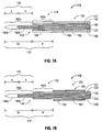
- Fig. 7A illustrates the feedline 120 and the radiating portion 118 of the triaxial antenna assembly 112 having a double-dipole antenna 140.
- the double-dipole antenna 140 is coupled to the feedline 120 that electrically connects the triaxial antenna assembly 112 to the generator 14.
- the radiating portion 118 includes an inner conductor 150 (e.g., a wire) surrounded by an inner insulator 152, which is surrounded by a central conductor 156 (e.g., a cylindrical conducting sheath).
- the radiating portion 118 also includes a central insulator 157 disposed around the central conductor 156, which is surrounded by an outer conductor 158.
- the inner, central and outer conductors 150, 156 and 158, respectively, may be constructed of copper, gold, stainless steel or other conductive metals with similar conductivity values. Much like the aforementioned conductors, the metals may be plated with other materials, e.g., other conductive materials, to improve their properties, e.g., to improve conductivity or decrease energy loss, etc.
- the outer conductor 158 may be surrounded by an outer jacket 159 defining a cavity 166 therebetween.
- the outer jacket 159 may be hollow and may include the cavity 166 inside thereof.
- the cavity 166 is in liquid communication with the ports 30 and 32 (see Fig. 6 ) for circulating the coolant fluid 37 therethrough.
- the outer conductor 158 may also include a solid conducting portion 168 disposed at the distal end thereof. The circulation of the coolant fluid 37 through the entire length of the cavity 166 that covers the feedline 120 removes the heat generated during ablation.
- the triaxial antenna assembly 112 is adapted to deliver microwave energy at two distinct frequencies (e.g., high frequency and low frequency).
- the inner and central conductors 150 and 156 represent the first dipole 170 of the double-dipole antenna 140, and are adapted to deliver microwave energy at a first frequency (e.g., 2450 MHz).
- the first dipole 170 and the outer conductor 158 represent the second dipole 172 of the double-dipole antenna 140 and are adapted to deliver microwave energy at a second frequency (e.g., 915 MHz).
- the central conductor 156 serves a dual purpose in the triaxial antenna assembly 112 - the central conductor 156 acts as an outer conductor for the inner conductor 150 during high frequency energy delivery and as an inner conductor for the outer conductor 158 during low frequency energy delivery.
- the inner conductor 150 extends outside the central conductor 156 by a first predetermined length a , which may be a quarter wavelength of the amplitude of the microwave energy supplied at 2450 MHz (e.g., ⁇ eHF /4, wherein HF is the first frequency or the high frequency).
- the central conductor 156 also extends outside the outer conductor 158 by the predetermined length a .
- the exposed sections of the inner and central conductors 150 and 156 define a high frequency radiating section 170 having a total length equal to the sum of lengths a (e.g., ⁇ eHF/2 ). More specifically, during application of high frequency microwave energy, the inner conductor 150 acts as a high frequency first pole 180a and the central conductor 156 acts as a high frequency second pole 180b for the first dipole 170 of the double-dipole antenna 140.
- the cooling cavity 166 extends from the proximal end of the conducting portion 168 along the feedline 120, covering the outer conductor 158.
- conductors 150 and 156 along with conducting portion 168 define a low frequency radiating section 172 having a total length of 2a + b .
- the length b may be any length suitable such that the sum of 2a + b represents a half wavelength of the amplitude of the microwave energy supplied at the low frequency (e.g., 915 MHz).
- the inner and central conductors 150 and 156 act as a low frequency first pole 182a
- the conducting portion 168 acts as a low frequency second pole 182b for the second dipole of the double-dipole antenna 140.
- the triaxial antenna assembly 112 includes a choke 160 that is disposed around the outer conductor 158.
- Choke 160 may include an inner dielectric layer 162 and an outer conductive layer 164.
- the choke 160 may be a quarter-wavelength shorted choke at the low frequency and is shorted to the outer conductor 158 at the proximal end of the choke 160 by soldering or other suitable methods.
- the choke 160 may replace the cooling cavity 166, and defines a portion of the radiating section 118 as a low frequency radiating section 172. More specifically, the choke 160 is disposed a second predetermined distance, length b , from the distal end of the inner conductor 150.
- Length b may be such that the sum of 2a + b represents half wavelength of the amplitude of the microwave energy supplied at 915 MHz (e.g., ⁇ eLF /2, wherein LF is the second frequency or the low frequency).
- the choke 160 is adapted to limit the bandwidth of the microwave energy only at the second frequency and does not interfere with the application of microwave energy at the first frequency.
- the inner and central conductors 150 and 156 act as a low frequency first pole 182a and a distal portion of the outer conductor 158 acts as a low frequency second pole 182b.
- the low frequency second pole 182b may have a length b such that in conjunction with the low frequency first pole 182a, the first and second poles 182a and 182b define a low frequency radiating section 172 having a total length equal to the sum of lengths 2a + b (e.g., ⁇ eLF /2).
- the dual-frequency operation of the antenna assembly 12 and the triaxial antenna assembly 112 allows for the production of lesions of varying shape and depth. More specifically, the total operative length (e.g., the resonating portion) of the antenna 40 of the assembly 12 ( Fig. 2 ) may be controlled by adjusting the frequency of the output of the generator 14. Since the depth of the lesion produced by the antenna 40 is directly related to the length of the resonating portion of the antenna 40, adjusting the relevant portions of the antenna 40 that resonate allows a user to control of the shape (e.g., diameter) and depth of the desired lesion.
- the shape e.g., diameter
- the shape of the lesion is controlled accordingly by nature of the inductor 74 disposed on the first pole 70 ( Fig. 5 ).
- the inductor 74 controls the operative length of the antenna 40 based on the frequency of the microwave energy supplied to the antenna 40.
- a method for forming a lesion includes the steps of supplying microwave energy at a predetermined frequency (e.g., first or second frequency) to the microwave antenna assembly 12 and adjusting the operative length of the dipole antenna 40 based on the frequency of the microwave energy supplied thereto to adjust at least one property (e.g., depth, circumference, shape, etc.) of the lesion.
- a predetermined frequency e.g., first or second frequency
- the depth of the desired lesion may also be varied.
- a low frequency e.g., 915 MHz
- the energy passes through the outer conductor 158 and the central conductor 156 thereby generating a lesion along the entire low frequency radiating section 172.
- a high frequency e.g., 2450 MHz
- the energy passes through the inner and central conductors 150 and 156, thereby generating a lesion only along the high frequency radiating section 170.
- energizing either or both sections 170 and 172 allows a user to generate varying depth lesions.
Landscapes
- Health & Medical Sciences (AREA)
- Surgery (AREA)
- Life Sciences & Earth Sciences (AREA)
- Medical Informatics (AREA)
- Animal Behavior & Ethology (AREA)
- Nuclear Medicine, Radiotherapy & Molecular Imaging (AREA)
- Electromagnetism (AREA)
- Engineering & Computer Science (AREA)
- Biomedical Technology (AREA)
- Heart & Thoracic Surgery (AREA)
- Physics & Mathematics (AREA)
- Molecular Biology (AREA)
- Otolaryngology (AREA)
- General Health & Medical Sciences (AREA)
- Public Health (AREA)
- Veterinary Medicine (AREA)
- Surgical Instruments (AREA)
- Radiation-Therapy Devices (AREA)
- Variable-Direction Aerials And Aerial Arrays (AREA)
- Support Of Aerials (AREA)
Claims (8)
- Ensemble d'antenne micro-ondes triaxial (112), comprenant:une ligne d'amenée (120) incluant un conducteur intérieur (150), un conducteur central (156) disposé autour du conducteur intérieur (150) et un conducteur extérieur (158) disposé autour du conducteur central; etune portion de rayonnement (118) incluant une section de rayonnement haute fréquence (170) et une section de rayonnement basse fréquence (172);l'ensemble étant caractérisé en comprenant:un étrangleur (160) disposé autour du conducteur extérieur et conçu pour limiter la largeur de bande de l'énergie micro-ondes seulement à la basse fréquence et pour ne pas interférer avec l'application de l'énergie micro-ondes à haute fréquence.
- Ensemble d'antenne micro-ondes triaxial selon la revendication 1, où la section de rayonnement haute fréquence comprend une portion du conducteur intérieur et une portion du conducteur central, et la section de rayonnement basse fréquence comprend la portion du conducteur central et une portion du conducteur extérieur.
- Ensemble d'antenne micro-ondes triaxial selon la revendication 2, où la portion du conducteur intérieur s'étend sur une première distance prédéterminée depuis le conducteur central, et la portion du conducteur central s'étend sur une première distance prédéterminée depuis le conducteur extérieur.
- Ensemble d'antenne micro-ondes triaxial selon la revendication 3, où la première distance prédéterminée est un quart de longueur d'onde de l'amplitude de l'énergie micro-ondes fournie à haute fréquence.
- Ensemble d'antenne micro-ondes triaxial selon la revendication 2, 3 ou 4, où le conducteur extérieur comprend une structure tubulaire définissant une cavité (166) à l'intérieur apte à faire circuler un fluide de refroidissement à travers celle-ci, où la cavité est disposée à une deuxième distance prédéterminée de la portion distale du conducteur extérieur.
- Ensemble d'antenne micro-ondes triaxial selon la revendication 5, où la somme du double de la première distance et de la deuxième distance prédéterminée représente une demi-longueur d'onde de l'amplitude de l'énergie micro-ondes fournie à basse fréquence.
- Ensemble d'antenne micro-ondes selon la revendication 3 ou 4, où l'étrangleur est disposé à une deuxième distance prédéterminée de la portion centrale du conducteur extérieur.
- Ensemble d'antenne micro-ondes selon la revendication 7, où la somme du double de la première distance et de la deuxième distance prédéterminée représente une demi-longueur d'onde de l'amplitude de l'énergie micro-ondes fournie à basse fréquence.
Applications Claiming Priority (1)
| Application Number | Priority Date | Filing Date | Title |
|---|---|---|---|
| US12/197,473 US9173706B2 (en) | 2008-08-25 | 2008-08-25 | Dual-band dipole microwave ablation antenna |
Publications (2)
| Publication Number | Publication Date |
|---|---|
| EP2158868A1 EP2158868A1 (fr) | 2010-03-03 |
| EP2158868B1 true EP2158868B1 (fr) | 2012-10-24 |
Family
ID=41170088
Family Applications (1)
| Application Number | Title | Priority Date | Filing Date |
|---|---|---|---|
| EP09010873A Ceased EP2158868B1 (fr) | 2008-08-25 | 2009-08-25 | Antenne dipôle et à double bande d'ablation aux micro-ondes |
Country Status (5)
| Country | Link |
|---|---|
| US (3) | US9173706B2 (fr) |
| EP (1) | EP2158868B1 (fr) |
| JP (1) | JP5420347B2 (fr) |
| AU (1) | AU2009212766B2 (fr) |
| CA (1) | CA2676522C (fr) |
Cited By (6)
| Publication number | Priority date | Publication date | Assignee | Title |
|---|---|---|---|---|
| US8894640B2 (en) | 2009-09-24 | 2014-11-25 | Covidien Lp | Optical detection of interrupted fluid flow to ablation probe |
| US8932281B2 (en) | 2011-01-05 | 2015-01-13 | Covidien Lp | Energy-delivery devices with flexible fluid-cooled shaft, inflow/outflow junctions suitable for use with same, and systems including same |
| US9011421B2 (en) | 2011-01-05 | 2015-04-21 | Covidien Lp | Energy-delivery devices with flexible fluid-cooled shaft, inflow/outflow junctions suitable for use with same, and systems including same |
| US9017319B2 (en) | 2011-01-05 | 2015-04-28 | Covidien Lp | Energy-delivery devices with flexible fluid-cooled shaft, inflow/outflow junctions suitable for use with same, and systems including same |
| US9028476B2 (en) | 2011-02-03 | 2015-05-12 | Covidien Lp | Dual antenna microwave resection and ablation device, system and method of use |
| US9192437B2 (en) | 2009-05-27 | 2015-11-24 | Covidien Lp | Narrow gauge high strength choked wet tip microwave ablation antenna |
Families Citing this family (57)
| Publication number | Priority date | Publication date | Assignee | Title |
|---|---|---|---|---|
| US7197363B2 (en) * | 2002-04-16 | 2007-03-27 | Vivant Medical, Inc. | Microwave antenna having a curved configuration |
| US10363092B2 (en) | 2006-03-24 | 2019-07-30 | Neuwave Medical, Inc. | Transmission line with heat transfer ability |
| US11389235B2 (en) | 2006-07-14 | 2022-07-19 | Neuwave Medical, Inc. | Energy delivery systems and uses thereof |
| US10376314B2 (en) | 2006-07-14 | 2019-08-13 | Neuwave Medical, Inc. | Energy delivery systems and uses thereof |
| US9622813B2 (en) | 2007-11-01 | 2017-04-18 | Covidien Lp | Method for volume determination and geometric reconstruction |
| US8280525B2 (en) | 2007-11-16 | 2012-10-02 | Vivant Medical, Inc. | Dynamically matched microwave antenna for tissue ablation |
| US8435237B2 (en) | 2008-01-29 | 2013-05-07 | Covidien Lp | Polyp encapsulation system and method |
| US9949794B2 (en) | 2008-03-27 | 2018-04-24 | Covidien Lp | Microwave ablation devices including expandable antennas and methods of use |
| US8192427B2 (en) | 2008-06-09 | 2012-06-05 | Tyco Healthcare Group Lp | Surface ablation process with electrode cooling methods |
| US9173706B2 (en) * | 2008-08-25 | 2015-11-03 | Covidien Lp | Dual-band dipole microwave ablation antenna |
| US8251987B2 (en) | 2008-08-28 | 2012-08-28 | Vivant Medical, Inc. | Microwave antenna |
| US8403924B2 (en) | 2008-09-03 | 2013-03-26 | Vivant Medical, Inc. | Shielding for an isolation apparatus used in a microwave generator |
| US8197473B2 (en) | 2009-02-20 | 2012-06-12 | Vivant Medical, Inc. | Leaky-wave antennas for medical applications |
| US8202270B2 (en) | 2009-02-20 | 2012-06-19 | Vivant Medical, Inc. | Leaky-wave antennas for medical applications |
| US9277969B2 (en) | 2009-04-01 | 2016-03-08 | Covidien Lp | Microwave ablation system with user-controlled ablation size and method of use |
| US8463396B2 (en) | 2009-05-06 | 2013-06-11 | Covidien LLP | Power-stage antenna integrated system with high-strength shaft |
| US8235981B2 (en) | 2009-06-02 | 2012-08-07 | Vivant Medical, Inc. | Electrosurgical devices with directional radiation pattern |
| ES2864688T3 (es) | 2009-07-28 | 2021-10-14 | Neuwave Medical Inc | Sistema de ablación |
| USD634010S1 (en) | 2009-08-05 | 2011-03-08 | Vivant Medical, Inc. | Medical device indicator guide |
| US9031668B2 (en) * | 2009-08-06 | 2015-05-12 | Covidien Lp | Vented positioner and spacer and method of use |
| US9113925B2 (en) * | 2009-09-09 | 2015-08-25 | Covidien Lp | System and method for performing an ablation procedure |
| US8069553B2 (en) | 2009-09-09 | 2011-12-06 | Vivant Medical, Inc. | Method for constructing a dipole antenna |
| US8355803B2 (en) | 2009-09-16 | 2013-01-15 | Vivant Medical, Inc. | Perfused core dielectrically loaded dipole microwave antenna probe |
| US9095359B2 (en) | 2009-09-18 | 2015-08-04 | Covidien Lp | Tissue ablation system with energy distribution |
| US9113926B2 (en) | 2009-09-29 | 2015-08-25 | Covidien Lp | Management of voltage standing wave ratio at skin surface during microwave ablation |
| US8568398B2 (en) | 2009-09-29 | 2013-10-29 | Covidien Lp | Flow rate monitor for fluid cooled microwave ablation probe |
| US8568401B2 (en) | 2009-10-27 | 2013-10-29 | Covidien Lp | System for monitoring ablation size |
| US8430871B2 (en) | 2009-10-28 | 2013-04-30 | Covidien Lp | System and method for monitoring ablation size |
| US8382750B2 (en) | 2009-10-28 | 2013-02-26 | Vivant Medical, Inc. | System and method for monitoring ablation size |
| US8491579B2 (en) * | 2010-02-05 | 2013-07-23 | Covidien Lp | Electrosurgical devices with choke shorted to biological tissue |
| US8409188B2 (en) * | 2010-03-26 | 2013-04-02 | Covidien Lp | Ablation devices with adjustable radiating section lengths, electrosurgical systems including same, and methods of adjusting ablation fields using same |
| JP6153865B2 (ja) | 2010-05-03 | 2017-06-28 | ニューウェーブ メディカル, インコーポレイテッドNeuwave Medical, Inc. | エネルギー送達システム |
| US8945144B2 (en) | 2010-09-08 | 2015-02-03 | Covidien Lp | Microwave spacers and method of use |
| USD673685S1 (en) | 2010-09-08 | 2013-01-01 | Vivant Medical, Inc. | Microwave device spacer and positioner with arcuate slot |
| US8968289B2 (en) | 2010-10-22 | 2015-03-03 | Covidien Lp | Microwave spacers and methods of use |
| US9770294B2 (en) | 2011-01-05 | 2017-09-26 | Covidien Lp | Energy-delivery devices with flexible fluid-cooled shaft, inflow/outflow junctions suitable for use with same, and systems including same |
| US10335230B2 (en) | 2011-03-09 | 2019-07-02 | Covidien Lp | Systems for thermal-feedback-controlled rate of fluid flow to fluid-cooled antenna assembly and methods of directing energy to tissue using same |
| CN107224325B (zh) * | 2011-12-21 | 2020-09-01 | 纽华沃医药公司 | 能量输送系统及其用途 |
| US9119648B2 (en) | 2012-01-06 | 2015-09-01 | Covidien Lp | System and method for treating tissue using an expandable antenna |
| US9113931B2 (en) | 2012-01-06 | 2015-08-25 | Covidien Lp | System and method for treating tissue using an expandable antenna |
| EA201590197A1 (ru) | 2012-08-23 | 2015-07-30 | Алиос Биофарма, Инк. | Соединения для лечения парамиксовирусных вирусных инфекций |
| MA41614A (fr) | 2015-02-25 | 2018-01-02 | Alios Biopharma Inc | Composés antiviraux |
| KR20180075603A (ko) | 2015-10-26 | 2018-07-04 | 뉴웨이브 메디컬, 인코포레이티드 | 의료 장치를 고정시키기 위한 기기 및 이의 관련 방법 |
| MX2018005116A (es) | 2015-10-26 | 2018-09-05 | Neuwave Medical Inc | Sistemas de suministro de energia y sus usos. |
| GB2550537B (en) * | 2016-02-11 | 2018-04-04 | Gyrus Medical Ltd | Microwave ablation antenna assemblies |
| CN109069203B (zh) | 2016-04-15 | 2021-06-22 | 纽韦弗医疗设备公司 | 用于能量输送的系统和方法 |
| US11000332B2 (en) | 2016-08-02 | 2021-05-11 | Covidien Lp | Ablation cable assemblies having a large diameter coaxial feed cable reduced to a small diameter at intended site |
| EP3381393A1 (fr) | 2017-03-31 | 2018-10-03 | National University of Ireland Galway | Sonde d'ablation |
| GB201708726D0 (en) * | 2017-06-01 | 2017-07-19 | Creo Medical Ltd | Electrosurgical instrument for ablation and resection |
| US10716619B2 (en) | 2017-06-19 | 2020-07-21 | Covidien Lp | Microwave and radiofrequency energy-transmitting tissue ablation systems |
| US20190246876A1 (en) | 2018-02-15 | 2019-08-15 | Neuwave Medical, Inc. | Compositions and methods for directing endoscopic devices |
| US11672596B2 (en) | 2018-02-26 | 2023-06-13 | Neuwave Medical, Inc. | Energy delivery devices with flexible and adjustable tips |
| US11160600B2 (en) | 2018-03-01 | 2021-11-02 | Covidien Lp | Monopolar return electrode grasper with return electrode monitoring |
| US12144538B2 (en) | 2018-03-29 | 2024-11-19 | National University Of Ireland, Galway | Ablation probe |
| WO2020019264A1 (fr) * | 2018-07-26 | 2020-01-30 | 华为技术有限公司 | Dispositif d'alimentation, antenne à micro-ondes à double fréquence et dispositif d'antenne à double fréquence |
| US11832879B2 (en) | 2019-03-08 | 2023-12-05 | Neuwave Medical, Inc. | Systems and methods for energy delivery |
| CN110701993B (zh) * | 2019-09-29 | 2021-08-03 | 广州佳昕机电科技有限公司 | 一种智能卡的天线埋深检测装置及检测方法 |
Citations (1)
| Publication number | Priority date | Publication date | Assignee | Title |
|---|---|---|---|---|
| EP1055400A1 (fr) * | 1999-05-28 | 2000-11-29 | Gyrus Medical Limited | Appareil électrochirurgical |
Family Cites Families (146)
| Publication number | Priority date | Publication date | Assignee | Title |
|---|---|---|---|---|
| DE390937C (de) | 1922-10-13 | 1924-03-03 | Adolf Erb | Vorrichtung zur Innenbeheizung von Wannenoefen zum Haerten, Anlassen, Gluehen, Vergueten und Schmelzen |
| DE1099658B (de) | 1959-04-29 | 1961-02-16 | Siemens Reiniger Werke Ag | Selbsttaetige Einschaltvorrichtung fuer Hochfrequenzchirurgiegeraete |
| FR1275415A (fr) | 1960-09-26 | 1961-11-10 | Dispositif détecteur de perturbations pour installations électriques, notamment d'électrochirurgie | |
| DE1139927B (de) | 1961-01-03 | 1962-11-22 | Friedrich Laber | Hochfrequenz-Chirurgiegeraet |
| DE1149832C2 (de) | 1961-02-25 | 1977-10-13 | Siemens AG, 1000 Berlin und 8000 München | Hochfrequenz-chirurgieapparat |
| FR1347865A (fr) | 1962-11-22 | 1964-01-04 | Perfectionnements aux appareils de diathermo-coagulation | |
| DE1439302B2 (de) | 1963-10-26 | 1971-05-19 | Siemens AG, 1000 Berlin u 8000 München | Hochfrequenz Chirurgiegerat |
| US3631363A (en) * | 1969-11-14 | 1971-12-28 | Gen Electric | High-frequency cavity oscillator having improved tuning means |
| SU401367A1 (ru) | 1971-10-05 | 1973-10-12 | Тернопольский государственный медицинский институт | Биактивный электрохирургическнп инструмент |
| FR2235669A1 (en) | 1973-07-07 | 1975-01-31 | Lunacek Boris | Gynaecological sterilisation instrument - has hollow electrode protruding from the end of a curved ended tube |
| GB1480736A (en) | 1973-08-23 | 1977-07-20 | Matburn Ltd | Electrodiathermy apparatus |
| DE2455174A1 (de) | 1973-11-21 | 1975-05-22 | Termiflex Corp | Ein/ausgabegeraet zum datenaustausch mit datenverarbeitungseinrichtungen |
| DE2407559C3 (de) | 1974-02-16 | 1982-01-21 | Dornier System Gmbh, 7990 Friedrichshafen | Wärmesonde |
| DE2415263A1 (de) | 1974-03-29 | 1975-10-02 | Aesculap Werke Ag | Chirurgische hf-koagulationssonde |
| DE2429021C2 (de) | 1974-06-18 | 1983-12-08 | Erbe Elektromedizin GmbH, 7400 Tübingen | Fernschalteinrichtung für ein HF-Chirurgiegerät |
| FR2276027A1 (fr) | 1974-06-25 | 1976-01-23 | Medical Plastics Inc | Raccordement electrique pour electrode plane |
| DE2460481A1 (de) | 1974-12-20 | 1976-06-24 | Delma Elektro Med App | Elektrodenhandgriff zur handfernschaltung eines hochfrequenz-chirurgiegeraets |
| US4237887A (en) | 1975-01-23 | 1980-12-09 | Valleylab, Inc. | Electrosurgical device |
| DE2504280C3 (de) | 1975-02-01 | 1980-08-28 | Hans Heinrich Prof. Dr. 8035 Gauting Meinke | Vorrichtung zum Schneiden und/oder Koagulieren menschlichen Gewebes mit Hochfrequenzstrom |
| CA1064581A (fr) | 1975-06-02 | 1979-10-16 | Stephen W. Andrews | Circuit de controle de pulsations et methode pour appareil d'electrochirurgie |
| FR2315286A2 (fr) | 1975-06-26 | 1977-01-21 | Lamidey Marcel | Pince a dissequer, hemostatique, haute frequence |
| DE2540968C2 (de) | 1975-09-13 | 1982-12-30 | Erbe Elektromedizin GmbH, 7400 Tübingen | Einrichtung zum Einschalten des Koagulationsstroms einer bipolaren Koagulationspinzette |
| FR2390968A1 (fr) | 1977-05-16 | 1978-12-15 | Skovajsa Joseph | Dispositif de traitement local d'un patient, notamment pour acupuncture ou auriculotherapie |
| SU727201A2 (ru) | 1977-11-02 | 1980-04-15 | Киевский Научно-Исследовательский Институт Нейрохирургии | Электрохирургический аппарат |
| DE2803275C3 (de) | 1978-01-26 | 1980-09-25 | Aesculap-Werke Ag Vormals Jetter & Scheerer, 7200 Tuttlingen | Fernschalteinrichtung zum Schalten eines monopolaren HF-Chirurgiegerätes |
| DE2823291A1 (de) | 1978-05-27 | 1979-11-29 | Rainer Ing Grad Koch | Schaltung zur automatischen einschaltung des hochfrequenzstromes von hochfrequenz-koagulationsgeraeten |
| DE2946728A1 (de) | 1979-11-20 | 1981-05-27 | Erbe Elektromedizin GmbH & Co KG, 7400 Tübingen | Hochfrequenz-chirurgiegeraet |
| US5097844A (en) * | 1980-04-02 | 1992-03-24 | Bsd Medical Corporation | Hyperthermia apparatus having three-dimensional focusing |
| US4798215A (en) * | 1984-03-15 | 1989-01-17 | Bsd Medical Corporation | Hyperthermia apparatus |
| US4462412A (en) * | 1980-04-02 | 1984-07-31 | Bsd Medical Corporation | Annular electromagnetic radiation applicator for biological tissue, and method |
| JPS5778844A (en) | 1980-11-04 | 1982-05-17 | Kogyo Gijutsuin | Lasre knife |
| DE3045996A1 (de) | 1980-12-05 | 1982-07-08 | Medic Eschmann Handelsgesellschaft für medizinische Instrumente mbH, 2000 Hamburg | Elektro-chirurgiegeraet |
| FR2502935B1 (fr) | 1981-03-31 | 1985-10-04 | Dolley Roger | Procede et dispositif de controle de la coagulation de tissus a l'aide d'un courant a haute frequence |
| DE3120102A1 (de) | 1981-05-20 | 1982-12-09 | F.L. Fischer GmbH & Co, 7800 Freiburg | Anordnung zur hochfrequenzkoagulation von eiweiss fuer chirurgische zwecke |
| US4397313A (en) * | 1981-08-03 | 1983-08-09 | Clini-Therm Corporation | Multiple microwave applicator system and method for microwave hyperthermia treatment |
| FR2517953A1 (fr) | 1981-12-10 | 1983-06-17 | Alvar Electronic | Appareil diaphanometre et son procede d'utilisation |
| US4583556A (en) * | 1982-12-13 | 1986-04-22 | M/A-Com, Inc. | Microwave applicator/receiver apparatus |
| FR2546409B1 (fr) * | 1983-05-26 | 1988-05-13 | Cgr Mev | Appareil d'hyperthermie |
| FR2573301B3 (fr) | 1984-11-16 | 1987-04-30 | Lamidey Gilles | Pince chirurgicale et son appareillage de commande et de controle |
| DE3510586A1 (de) | 1985-03-23 | 1986-10-02 | Erbe Elektromedizin GmbH, 7400 Tübingen | Kontrolleinrichtung fuer ein hochfrequenz-chirurgiegeraet |
| DE3604823C2 (de) | 1986-02-15 | 1995-06-01 | Lindenmeier Heinz | Hochfrequenzgenerator mit automatischer Leistungsregelung für die Hochfrequenzchirurgie |
| JPH055106Y2 (fr) | 1986-02-28 | 1993-02-09 | ||
| US5554176A (en) * | 1986-05-15 | 1996-09-10 | Telectronics Pacing Systems, Inc. | Implantable electrode and sensor lead apparatus |
| EP0246350A1 (fr) | 1986-05-23 | 1987-11-25 | Erbe Elektromedizin GmbH. | Electrode pour coaguler |
| JPH0540112Y2 (fr) | 1987-03-03 | 1993-10-12 | ||
| DE3711511C1 (de) | 1987-04-04 | 1988-06-30 | Hartmann & Braun Ag | Verfahren zur Bestimmung der Gaskonzentrationen in einem Gasgemisch und Sensor zur Messung der Waermeleitfaehigkeit |
| DE8712328U1 (de) | 1987-09-11 | 1988-02-18 | Jakoubek, Franz, 7201 Emmingen-Liptingen | Endoskopiezange |
| EP0415997A4 (en) * | 1988-05-18 | 1992-04-08 | Kasevich Associates, Inc. | Microwave balloon angioplasty |
| US5129396A (en) * | 1988-11-10 | 1992-07-14 | Arye Rosen | Microwave aided balloon angioplasty with lumen measurement |
| DE3904558C2 (de) | 1989-02-15 | 1997-09-18 | Lindenmeier Heinz | Automatisch leistungsgeregelter Hochfrequenzgenerator für die Hochfrequenz-Chirurgie |
| DE3926934A1 (de) * | 1989-08-16 | 1991-02-21 | Deutsches Krebsforsch | Hyperthermie-mikrowellenapplikator zur erwaermung einer begrenzten umgebung in einem dissipativen medium |
| DE3942998C2 (de) | 1989-12-27 | 1998-11-26 | Delma Elektro Med App | Elektrochirurgisches Hochfrequenzgerät |
| JP2514450B2 (ja) * | 1990-03-01 | 1996-07-10 | 原田工業株式会社 | スリ―ブ付自動車用三波共用アンテナ |
| US5221269A (en) | 1990-10-15 | 1993-06-22 | Cook Incorporated | Guide for localizing a nonpalpable breast lesion |
| US5301687A (en) * | 1991-06-06 | 1994-04-12 | Trustees Of Dartmouth College | Microwave applicator for transurethral hyperthermia |
| US5417210A (en) * | 1992-05-27 | 1995-05-23 | International Business Machines Corporation | System and method for augmentation of endoscopic surgery |
| DE4122050C2 (de) | 1991-07-03 | 1996-05-30 | Gore W L & Ass Gmbh | Antennenanordnung mit Zuleitung zur medizinischen Wärmeapplikation in Körperhohlräumen |
| US5366477A (en) | 1991-10-17 | 1994-11-22 | American Cyanamid Company | Actuating forces transmission link and assembly for use in surgical instruments |
| US5323778A (en) * | 1991-11-05 | 1994-06-28 | Brigham & Women's Hospital | Method and apparatus for magnetic resonance imaging and heating tissues |
| DE4238263A1 (en) | 1991-11-15 | 1993-05-19 | Minnesota Mining & Mfg | Adhesive comprising hydrogel and crosslinked polyvinyl:lactam - is used in electrodes for biomedical application providing low impedance and good mechanical properties when water and/or moisture is absorbed from skin |
| US5681282A (en) * | 1992-01-07 | 1997-10-28 | Arthrocare Corporation | Methods and apparatus for ablation of luminal tissues |
| DE4205213A1 (de) | 1992-02-20 | 1993-08-26 | Delma Elektro Med App | Hochfrequenzchirurgiegeraet |
| FR2687786B1 (fr) | 1992-02-26 | 1994-05-06 | Pechiney Recherche | Mesure de la resistivite electrique et de la conductivite thermique a haute temperature de produits refractaires. |
| CA2094220A1 (fr) | 1992-05-21 | 1993-11-22 | Mark A. Rydell | Ciseaux chirurgicaux permettant la coagulation bipolaire |
| DE4303882C2 (de) | 1993-02-10 | 1995-02-09 | Kernforschungsz Karlsruhe | Kombinationsinstrument zum Trennen und Koagulieren für die minimal invasive Chirurgie |
| GB9309142D0 (en) | 1993-05-04 | 1993-06-16 | Gyrus Medical Ltd | Laparoscopic instrument |
| US5405346A (en) * | 1993-05-14 | 1995-04-11 | Fidus Medical Technology Corporation | Tunable microwave ablation catheter |
| US5693082A (en) * | 1993-05-14 | 1997-12-02 | Fidus Medical Technology Corporation | Tunable microwave ablation catheter system and method |
| JPH07106840A (ja) * | 1993-10-07 | 1995-04-21 | Harada Ind Co Ltd | 二波共用スリーブアンテナ |
| GB9322464D0 (en) | 1993-11-01 | 1993-12-22 | Gyrus Medical Ltd | Electrosurgical apparatus |
| DE4339049C2 (de) | 1993-11-16 | 2001-06-28 | Erbe Elektromedizin | Einrichtung zur Konfiguration chirurgischer Systeme |
| GB9413070D0 (en) | 1994-06-29 | 1994-08-17 | Gyrus Medical Ltd | Electrosurgical apparatus |
| GB9425781D0 (en) | 1994-12-21 | 1995-02-22 | Gyrus Medical Ltd | Electrosurgical instrument |
| US6293942B1 (en) | 1995-06-23 | 2001-09-25 | Gyrus Medical Limited | Electrosurgical generator method |
| US6496738B2 (en) * | 1995-09-06 | 2002-12-17 | Kenneth L. Carr | Dual frequency microwave heating apparatus |
| DE19608716C1 (de) | 1996-03-06 | 1997-04-17 | Aesculap Ag | Bipolares chirurgisches Faßinstrument |
| AU2931897A (en) | 1996-05-06 | 1997-11-26 | Thermal Therapeutics, Inc. | Transcervical intrauterine applicator for intrauterine hyperthermia |
| AU3204097A (en) | 1996-05-22 | 1997-12-09 | Somnus Medical Technologies, Inc. | Method and apparatus for ablating turbinates |
| DE29616210U1 (de) | 1996-09-18 | 1996-11-14 | Olympus Winter & Ibe Gmbh, 22045 Hamburg | Handhabe für chirurgische Instrumente |
| DE19643127A1 (de) | 1996-10-18 | 1998-04-23 | Berchtold Gmbh & Co Geb | Hochfrequenzchirurgiegerät und Verfahren zu dessen Betrieb |
| US5923475A (en) | 1996-11-27 | 1999-07-13 | Eastman Kodak Company | Laser printer using a fly's eye integrator |
| DE19717411A1 (de) | 1997-04-25 | 1998-11-05 | Aesculap Ag & Co Kg | Verfahren und Vorrichtung zur Überwachung der thermischen Belastung des Gewebes eines Patienten |
| US6591049B2 (en) | 1997-07-02 | 2003-07-08 | Lumitex, Inc. | Light delivery systems and applications thereof |
| DE19751108A1 (de) | 1997-11-18 | 1999-05-20 | Beger Frank Michael Dipl Desig | Elektrochirurgisches Operationswerkzeug |
| US6031375A (en) * | 1997-11-26 | 2000-02-29 | The Johns Hopkins University | Method of magnetic resonance analysis employing cylindrical coordinates and an associated apparatus |
| EP0923907A1 (fr) | 1997-12-19 | 1999-06-23 | Gyrus Medical Limited | Instrument électrochirurgical. |
| DE19801173C1 (de) | 1998-01-15 | 1999-07-15 | Kendall Med Erzeugnisse Gmbh | Klemmverbinder für Filmelektroden |
| DE19848540A1 (de) | 1998-10-21 | 2000-05-25 | Reinhard Kalfhaus | Schaltungsanordnung und Verfahren zum Betreiben eines Wechselrichters |
| US7070595B2 (en) | 1998-12-14 | 2006-07-04 | Medwaves, Inc. | Radio-frequency based catheter system and method for ablating biological tissues |
| US6427089B1 (en) | 1999-02-19 | 2002-07-30 | Edward W. Knowlton | Stomach treatment apparatus and method |
| GB9904373D0 (en) * | 1999-02-25 | 1999-04-21 | Microsulis Plc | Radiation applicator |
| US6287297B1 (en) | 1999-03-05 | 2001-09-11 | Plc Medical Systems, Inc. | Energy delivery system and method for performing myocardial revascular |
| US20020022836A1 (en) * | 1999-03-05 | 2002-02-21 | Gyrus Medical Limited | Electrosurgery system |
| US6375606B1 (en) * | 1999-03-17 | 2002-04-23 | Stereotaxis, Inc. | Methods of and apparatus for treating vascular defects |
| GB9911956D0 (en) | 1999-05-21 | 1999-07-21 | Gyrus Medical Ltd | Electrosurgery system and method |
| GB9911954D0 (en) | 1999-05-21 | 1999-07-21 | Gyrus Medical Ltd | Electrosurgery system and instrument |
| GB9912625D0 (en) | 1999-05-28 | 1999-07-28 | Gyrus Medical Ltd | An electrosurgical generator and system |
| GB9913652D0 (en) | 1999-06-11 | 1999-08-11 | Gyrus Medical Ltd | An electrosurgical generator |
| WO2001001847A1 (fr) | 1999-07-06 | 2001-01-11 | Inbae Yoon | Endoscope de penetration et instrument chirurgical endoscopique a capteur d'images cmos et visuel |
| US6725080B2 (en) * | 2000-03-01 | 2004-04-20 | Surgical Navigation Technologies, Inc. | Multiple cannula image guided tool for image guided procedures |
| AU2001251134B2 (en) | 2000-03-31 | 2006-02-02 | Angiodynamics, Inc. | Tissue biopsy and treatment apparatus and method |
| DE10027727C1 (de) | 2000-06-03 | 2001-12-06 | Aesculap Ag & Co Kg | Scheren- oder zangenförmiges chirurgisches Instrument |
| US6866624B2 (en) | 2000-12-08 | 2005-03-15 | Medtronic Ave,Inc. | Apparatus and method for treatment of malignant tumors |
| US6603994B2 (en) * | 2000-12-28 | 2003-08-05 | Scimed Life Systems, Inc. | Apparatus and method for internally inducing a magnetic field in an aneurysm to embolize aneurysm with magnetically-controllable substance |
| ITPI20010006A1 (it) * | 2001-01-31 | 2002-07-31 | Cnr Consiglio Naz Delle Ricer | Antenna interstiziale con choke miniaturizzato per applicazioni di ipertemia a microonde in medicina e chirurgia |
| US20050014901A1 (en) * | 2001-07-10 | 2005-01-20 | Ips Corporation | Adhesive compositions for bonding and filling large assemblies |
| US6878147B2 (en) | 2001-11-02 | 2005-04-12 | Vivant Medical, Inc. | High-strength microwave antenna assemblies |
| DE10224154A1 (de) | 2002-05-27 | 2003-12-18 | Celon Ag Medical Instruments | Vorrichtung zum elektrochirurgischen Veröden von Körpergewebe |
| WO2004052169A2 (fr) * | 2002-09-27 | 2004-06-24 | The Trustees Of Dartmouth College | Imagerie par adsorption par resonance magnetique, elastographie et tomographie |
| US7697972B2 (en) * | 2002-11-19 | 2010-04-13 | Medtronic Navigation, Inc. | Navigation system for cardiac therapies |
| US6961028B2 (en) * | 2003-01-17 | 2005-11-01 | Lockheed Martin Corporation | Low profile dual frequency dipole antenna structure |
| JP2004290266A (ja) * | 2003-03-25 | 2004-10-21 | Olympus Corp | 処置装置 |
| US6932776B2 (en) * | 2003-06-02 | 2005-08-23 | Meridian Medicalssystems, Llc | Method and apparatus for detecting and treating vulnerable plaques |
| DE10328514B3 (de) | 2003-06-20 | 2005-03-03 | Aesculap Ag & Co. Kg | Chirurgisches Instrument |
| GB2403148C2 (en) | 2003-06-23 | 2013-02-13 | Microsulis Ltd | Radiation applicator |
| US7311703B2 (en) * | 2003-07-18 | 2007-12-25 | Vivant Medical, Inc. | Devices and methods for cooling microwave antennas |
| FR2862813B1 (fr) | 2003-11-20 | 2006-06-02 | Pellenc Sa | Procede de chargement equilibre d'une batterie lithium-ion ou lithium polymere |
| FR2864439B1 (fr) | 2003-12-30 | 2010-12-03 | Image Guided Therapy | Dispositif de traitement d'un volume de tissu biologique par hyperthermie localisee |
| JP4133855B2 (ja) * | 2004-02-03 | 2008-08-13 | Dxアンテナ株式会社 | 多周波数アンテナ |
| US6950076B2 (en) * | 2004-02-16 | 2005-09-27 | The Boeing Company | Two-dimensional dual-frequency antenna and associated down-conversion method |
| US6999041B2 (en) * | 2004-02-16 | 2006-02-14 | The Boeing Company | Dual frequency antennas and associated down-conversion method |
| US7101369B2 (en) * | 2004-04-29 | 2006-09-05 | Wisconsin Alumni Research Foundation | Triaxial antenna for microwave tissue ablation |
| US7244254B2 (en) | 2004-04-29 | 2007-07-17 | Micrablate | Air-core microwave ablation antennas |
| US7467015B2 (en) * | 2004-04-29 | 2008-12-16 | Neuwave Medical, Inc. | Segmented catheter for tissue ablation |
| DE102004022206B4 (de) | 2004-05-04 | 2006-05-11 | Bundesrepublik Deutschland, vertr. d. d. Bundesministerium für Wirtschaft und Arbeit, dieses vertr. d. d. Präsidenten der Physikalisch-Technischen Bundesanstalt | Sensor und Sensoranordnung zur Messung der Wärmeleitfähigkeit einer Probe |
| TWI279030B (en) * | 2004-06-21 | 2007-04-11 | Accton Technology Corp | Antenna and antenna array |
| WO2006127847A2 (fr) * | 2005-05-24 | 2006-11-30 | Micrablate, Llc | Dispositif chirurgical a ondes millimetriques |
| WO2006138382A2 (fr) * | 2005-06-14 | 2006-12-28 | Micrablate, Llc | Outil de resection de tissus a ondes millimetriques |
| DE202005015147U1 (de) | 2005-09-26 | 2006-02-09 | Health & Life Co., Ltd., Chung-Ho | Biosensor-Teststreifen mit Identifizierfunktion |
| US7565207B2 (en) * | 2005-11-22 | 2009-07-21 | Bsd Medical Corporation | Apparatus for creating hyperthermia in tissue |
| US8882766B2 (en) | 2006-01-24 | 2014-11-11 | Covidien Ag | Method and system for controlling delivery of energy to divide tissue |
| US10363092B2 (en) | 2006-03-24 | 2019-07-30 | Neuwave Medical, Inc. | Transmission line with heat transfer ability |
| US7777130B2 (en) * | 2007-06-18 | 2010-08-17 | Vivant Medical, Inc. | Microwave cable cooling |
| US9949794B2 (en) | 2008-03-27 | 2018-04-24 | Covidien Lp | Microwave ablation devices including expandable antennas and methods of use |
| US9198723B2 (en) | 2008-03-31 | 2015-12-01 | Covidien Lp | Re-hydration antenna for ablation |
| US8834409B2 (en) | 2008-07-29 | 2014-09-16 | Covidien Lp | Method for ablation volume determination and geometric reconstruction |
| US9173706B2 (en) | 2008-08-25 | 2015-11-03 | Covidien Lp | Dual-band dipole microwave ablation antenna |
| US8118808B2 (en) | 2009-03-10 | 2012-02-21 | Vivant Medical, Inc. | Cooled dielectrically buffered microwave dipole antenna |
| US9277969B2 (en) | 2009-04-01 | 2016-03-08 | Covidien Lp | Microwave ablation system with user-controlled ablation size and method of use |
| US10045819B2 (en) | 2009-04-14 | 2018-08-14 | Covidien Lp | Frequency identification for microwave ablation probes |
| US8463396B2 (en) | 2009-05-06 | 2013-06-11 | Covidien LLP | Power-stage antenna integrated system with high-strength shaft |
| US8216227B2 (en) | 2009-05-06 | 2012-07-10 | Vivant Medical, Inc. | Power-stage antenna integrated system with junction member |
| US8353903B2 (en) | 2009-05-06 | 2013-01-15 | Vivant Medical, Inc. | Power-stage antenna integrated system |
| US8292881B2 (en) | 2009-05-27 | 2012-10-23 | Vivant Medical, Inc. | Narrow gauge high strength choked wet tip microwave ablation antenna |
| US8834460B2 (en) | 2009-05-29 | 2014-09-16 | Covidien Lp | Microwave ablation safety pad, microwave safety pad system and method of use |
| US8235981B2 (en) | 2009-06-02 | 2012-08-07 | Vivant Medical, Inc. | Electrosurgical devices with directional radiation pattern |
-
2008
- 2008-08-25 US US12/197,473 patent/US9173706B2/en active Active
-
2009
- 2009-08-24 AU AU2009212766A patent/AU2009212766B2/en not_active Ceased
- 2009-08-24 CA CA2676522A patent/CA2676522C/fr not_active Expired - Fee Related
- 2009-08-24 JP JP2009193371A patent/JP5420347B2/ja not_active Expired - Fee Related
- 2009-08-25 EP EP09010873A patent/EP2158868B1/fr not_active Ceased
-
2015
- 2015-10-27 US US14/923,868 patent/US9439730B2/en active Active
-
2016
- 2016-08-24 US US15/245,301 patent/US20160361118A1/en not_active Abandoned
Patent Citations (1)
| Publication number | Priority date | Publication date | Assignee | Title |
|---|---|---|---|---|
| EP1055400A1 (fr) * | 1999-05-28 | 2000-11-29 | Gyrus Medical Limited | Appareil électrochirurgical |
Cited By (6)
| Publication number | Priority date | Publication date | Assignee | Title |
|---|---|---|---|---|
| US9192437B2 (en) | 2009-05-27 | 2015-11-24 | Covidien Lp | Narrow gauge high strength choked wet tip microwave ablation antenna |
| US8894640B2 (en) | 2009-09-24 | 2014-11-25 | Covidien Lp | Optical detection of interrupted fluid flow to ablation probe |
| US8932281B2 (en) | 2011-01-05 | 2015-01-13 | Covidien Lp | Energy-delivery devices with flexible fluid-cooled shaft, inflow/outflow junctions suitable for use with same, and systems including same |
| US9011421B2 (en) | 2011-01-05 | 2015-04-21 | Covidien Lp | Energy-delivery devices with flexible fluid-cooled shaft, inflow/outflow junctions suitable for use with same, and systems including same |
| US9017319B2 (en) | 2011-01-05 | 2015-04-28 | Covidien Lp | Energy-delivery devices with flexible fluid-cooled shaft, inflow/outflow junctions suitable for use with same, and systems including same |
| US9028476B2 (en) | 2011-02-03 | 2015-05-12 | Covidien Lp | Dual antenna microwave resection and ablation device, system and method of use |
Also Published As
| Publication number | Publication date |
|---|---|
| US9439730B2 (en) | 2016-09-13 |
| US9173706B2 (en) | 2015-11-03 |
| EP2158868A1 (fr) | 2010-03-03 |
| AU2009212766B2 (en) | 2013-09-19 |
| AU2009212766A1 (en) | 2010-03-11 |
| CA2676522A1 (fr) | 2010-02-25 |
| US20100045558A1 (en) | 2010-02-25 |
| CA2676522C (fr) | 2016-11-29 |
| JP2010050975A (ja) | 2010-03-04 |
| US20160361118A1 (en) | 2016-12-15 |
| JP5420347B2 (ja) | 2014-02-19 |
| US20160045260A1 (en) | 2016-02-18 |
Similar Documents
| Publication | Publication Date | Title |
|---|---|---|
| EP2158868B1 (fr) | Antenne dipôle et à double bande d'ablation aux micro-ondes | |
| US20100045559A1 (en) | Dual-Band Dipole Microwave Ablation Antenna | |
| US20250281237A1 (en) | Choked dielectric loaded tip dipole microwave antenna | |
| EP2008604B1 (fr) | Applicateur à micro-ondes à large bande | |
| EP2177173B1 (fr) | Antenne à micro-ondes dipôle à pointe chargée diélectrique étranglée | |
| EP2128929B1 (fr) | Antenne à micro-ondes à papillon coulissant | |
| AU2017219068B2 (en) | Dual-band dipole microwave ablation antenna | |
| AU2013273707B2 (en) | Dual-band dipole microwave ablation antenna | |
| AU2015261719B2 (en) | Slidable choke microwave antenna | |
| AU2014201120B2 (en) | Slidable choke microwave antenna |
Legal Events
| Date | Code | Title | Description |
|---|---|---|---|
| PUAI | Public reference made under article 153(3) epc to a published international application that has entered the european phase |
Free format text: ORIGINAL CODE: 0009012 |
|
| AK | Designated contracting states |
Kind code of ref document: A1 Designated state(s): AT BE BG CH CY CZ DE DK EE ES FI FR GB GR HR HU IE IS IT LI LT LU LV MC MK MT NL NO PL PT RO SE SI SK SM TR |
|
| AX | Request for extension of the european patent |
Extension state: AL BA RS |
|
| 17P | Request for examination filed |
Effective date: 20100902 |
|
| 17Q | First examination report despatched |
Effective date: 20101020 |
|
| GRAP | Despatch of communication of intention to grant a patent |
Free format text: ORIGINAL CODE: EPIDOSNIGR1 |
|
| GRAS | Grant fee paid |
Free format text: ORIGINAL CODE: EPIDOSNIGR3 |
|
| GRAA | (expected) grant |
Free format text: ORIGINAL CODE: 0009210 |
|
| AK | Designated contracting states |
Kind code of ref document: B1 Designated state(s): AT BE BG CH CY CZ DE DK EE ES FI FR GB GR HR HU IE IS IT LI LT LU LV MC MK MT NL NO PL PT RO SE SI SK SM TR |
|
| REG | Reference to a national code |
Ref country code: GB Ref legal event code: FG4D |
|
| REG | Reference to a national code |
Ref country code: CH Ref legal event code: EP |
|
| REG | Reference to a national code |
Ref country code: AT Ref legal event code: REF Ref document number: 580474 Country of ref document: AT Kind code of ref document: T Effective date: 20121115 |
|
| REG | Reference to a national code |
Ref country code: IE Ref legal event code: FG4D |
|
| REG | Reference to a national code |
Ref country code: DE Ref legal event code: R096 Ref document number: 602009010573 Country of ref document: DE Effective date: 20121220 |
|
| REG | Reference to a national code |
Ref country code: AT Ref legal event code: MK05 Ref document number: 580474 Country of ref document: AT Kind code of ref document: T Effective date: 20121024 |
|
| REG | Reference to a national code |
Ref country code: NL Ref legal event code: VDEP Effective date: 20121024 |
|
| PG25 | Lapsed in a contracting state [announced via postgrant information from national office to epo] |
Ref country code: NO Free format text: LAPSE BECAUSE OF FAILURE TO SUBMIT A TRANSLATION OF THE DESCRIPTION OR TO PAY THE FEE WITHIN THE PRESCRIBED TIME-LIMIT Effective date: 20130124 Ref country code: SE Free format text: LAPSE BECAUSE OF FAILURE TO SUBMIT A TRANSLATION OF THE DESCRIPTION OR TO PAY THE FEE WITHIN THE PRESCRIBED TIME-LIMIT Effective date: 20121024 Ref country code: NL Free format text: LAPSE BECAUSE OF FAILURE TO SUBMIT A TRANSLATION OF THE DESCRIPTION OR TO PAY THE FEE WITHIN THE PRESCRIBED TIME-LIMIT Effective date: 20121024 Ref country code: IS Free format text: LAPSE BECAUSE OF FAILURE TO SUBMIT A TRANSLATION OF THE DESCRIPTION OR TO PAY THE FEE WITHIN THE PRESCRIBED TIME-LIMIT Effective date: 20130224 Ref country code: FI Free format text: LAPSE BECAUSE OF FAILURE TO SUBMIT A TRANSLATION OF THE DESCRIPTION OR TO PAY THE FEE WITHIN THE PRESCRIBED TIME-LIMIT Effective date: 20121024 Ref country code: HR Free format text: LAPSE BECAUSE OF FAILURE TO SUBMIT A TRANSLATION OF THE DESCRIPTION OR TO PAY THE FEE WITHIN THE PRESCRIBED TIME-LIMIT Effective date: 20121024 |
|
| PG25 | Lapsed in a contracting state [announced via postgrant information from national office to epo] |
Ref country code: GR Free format text: LAPSE BECAUSE OF FAILURE TO SUBMIT A TRANSLATION OF THE DESCRIPTION OR TO PAY THE FEE WITHIN THE PRESCRIBED TIME-LIMIT Effective date: 20130125 Ref country code: LV Free format text: LAPSE BECAUSE OF FAILURE TO SUBMIT A TRANSLATION OF THE DESCRIPTION OR TO PAY THE FEE WITHIN THE PRESCRIBED TIME-LIMIT Effective date: 20121024 Ref country code: BE Free format text: LAPSE BECAUSE OF FAILURE TO SUBMIT A TRANSLATION OF THE DESCRIPTION OR TO PAY THE FEE WITHIN THE PRESCRIBED TIME-LIMIT Effective date: 20121024 Ref country code: SI Free format text: LAPSE BECAUSE OF FAILURE TO SUBMIT A TRANSLATION OF THE DESCRIPTION OR TO PAY THE FEE WITHIN THE PRESCRIBED TIME-LIMIT Effective date: 20121024 Ref country code: PL Free format text: LAPSE BECAUSE OF FAILURE TO SUBMIT A TRANSLATION OF THE DESCRIPTION OR TO PAY THE FEE WITHIN THE PRESCRIBED TIME-LIMIT Effective date: 20121024 Ref country code: PT Free format text: LAPSE BECAUSE OF FAILURE TO SUBMIT A TRANSLATION OF THE DESCRIPTION OR TO PAY THE FEE WITHIN THE PRESCRIBED TIME-LIMIT Effective date: 20130225 |
|
| PG25 | Lapsed in a contracting state [announced via postgrant information from national office to epo] |
Ref country code: AT Free format text: LAPSE BECAUSE OF FAILURE TO SUBMIT A TRANSLATION OF THE DESCRIPTION OR TO PAY THE FEE WITHIN THE PRESCRIBED TIME-LIMIT Effective date: 20121024 |
|
| PG25 | Lapsed in a contracting state [announced via postgrant information from national office to epo] |
Ref country code: BG Free format text: LAPSE BECAUSE OF FAILURE TO SUBMIT A TRANSLATION OF THE DESCRIPTION OR TO PAY THE FEE WITHIN THE PRESCRIBED TIME-LIMIT Effective date: 20130124 Ref country code: EE Free format text: LAPSE BECAUSE OF FAILURE TO SUBMIT A TRANSLATION OF THE DESCRIPTION OR TO PAY THE FEE WITHIN THE PRESCRIBED TIME-LIMIT Effective date: 20121024 Ref country code: CZ Free format text: LAPSE BECAUSE OF FAILURE TO SUBMIT A TRANSLATION OF THE DESCRIPTION OR TO PAY THE FEE WITHIN THE PRESCRIBED TIME-LIMIT Effective date: 20121024 Ref country code: SK Free format text: LAPSE BECAUSE OF FAILURE TO SUBMIT A TRANSLATION OF THE DESCRIPTION OR TO PAY THE FEE WITHIN THE PRESCRIBED TIME-LIMIT Effective date: 20121024 Ref country code: DK Free format text: LAPSE BECAUSE OF FAILURE TO SUBMIT A TRANSLATION OF THE DESCRIPTION OR TO PAY THE FEE WITHIN THE PRESCRIBED TIME-LIMIT Effective date: 20121024 |
|
| PG25 | Lapsed in a contracting state [announced via postgrant information from national office to epo] |
Ref country code: IT Free format text: LAPSE BECAUSE OF FAILURE TO SUBMIT A TRANSLATION OF THE DESCRIPTION OR TO PAY THE FEE WITHIN THE PRESCRIBED TIME-LIMIT Effective date: 20121024 Ref country code: RO Free format text: LAPSE BECAUSE OF FAILURE TO SUBMIT A TRANSLATION OF THE DESCRIPTION OR TO PAY THE FEE WITHIN THE PRESCRIBED TIME-LIMIT Effective date: 20121024 |
|
| PLBE | No opposition filed within time limit |
Free format text: ORIGINAL CODE: 0009261 |
|
| STAA | Information on the status of an ep patent application or granted ep patent |
Free format text: STATUS: NO OPPOSITION FILED WITHIN TIME LIMIT |
|
| 26N | No opposition filed |
Effective date: 20130725 |
|
| PG25 | Lapsed in a contracting state [announced via postgrant information from national office to epo] |
Ref country code: ES Free format text: LAPSE BECAUSE OF FAILURE TO SUBMIT A TRANSLATION OF THE DESCRIPTION OR TO PAY THE FEE WITHIN THE PRESCRIBED TIME-LIMIT Effective date: 20130204 |
|
| REG | Reference to a national code |
Ref country code: DE Ref legal event code: R082 Ref document number: 602009010573 Country of ref document: DE Representative=s name: HOFFMANN - EITLE, DE Effective date: 20130926 Ref country code: DE Ref legal event code: R081 Ref document number: 602009010573 Country of ref document: DE Owner name: COVIDIEN LP, US Free format text: FORMER OWNER: VIVANT MEDICAL, INC., BOULDER, US Effective date: 20130926 Ref country code: DE Ref legal event code: R081 Ref document number: 602009010573 Country of ref document: DE Owner name: COVIDIEN LP, MANSFIELD, US Free format text: FORMER OWNER: VIVANT MEDICAL, INC., BOULDER, COL., US Effective date: 20130926 Ref country code: DE Ref legal event code: R082 Ref document number: 602009010573 Country of ref document: DE Representative=s name: HOFFMANN - EITLE PATENT- UND RECHTSANWAELTE PA, DE Effective date: 20130926 |
|
| REG | Reference to a national code |
Ref country code: DE Ref legal event code: R097 Ref document number: 602009010573 Country of ref document: DE Effective date: 20130725 |
|
| PG25 | Lapsed in a contracting state [announced via postgrant information from national office to epo] |
Ref country code: CY Free format text: LAPSE BECAUSE OF FAILURE TO SUBMIT A TRANSLATION OF THE DESCRIPTION OR TO PAY THE FEE WITHIN THE PRESCRIBED TIME-LIMIT Effective date: 20121024 |
|
| REG | Reference to a national code |
Ref country code: GB Ref legal event code: 732E Free format text: REGISTERED BETWEEN 20131114 AND 20131120 |
|
| REG | Reference to a national code |
Ref country code: FR Ref legal event code: TP Owner name: COVIDIEN LP., US Effective date: 20131202 Ref country code: FR Ref legal event code: CD Owner name: COVIDIEN LP., US Effective date: 20131202 |
|
| REG | Reference to a national code |
Ref country code: CH Ref legal event code: PL |
|
| PG25 | Lapsed in a contracting state [announced via postgrant information from national office to epo] |
Ref country code: LI Free format text: LAPSE BECAUSE OF NON-PAYMENT OF DUE FEES Effective date: 20130831 Ref country code: CH Free format text: LAPSE BECAUSE OF NON-PAYMENT OF DUE FEES Effective date: 20130831 Ref country code: MC Free format text: LAPSE BECAUSE OF FAILURE TO SUBMIT A TRANSLATION OF THE DESCRIPTION OR TO PAY THE FEE WITHIN THE PRESCRIBED TIME-LIMIT Effective date: 20121024 |
|
| PG25 | Lapsed in a contracting state [announced via postgrant information from national office to epo] |
Ref country code: LT Free format text: LAPSE BECAUSE OF FAILURE TO SUBMIT A TRANSLATION OF THE DESCRIPTION OR TO PAY THE FEE WITHIN THE PRESCRIBED TIME-LIMIT Effective date: 20121024 |
|
| PG25 | Lapsed in a contracting state [announced via postgrant information from national office to epo] |
Ref country code: SM Free format text: LAPSE BECAUSE OF FAILURE TO SUBMIT A TRANSLATION OF THE DESCRIPTION OR TO PAY THE FEE WITHIN THE PRESCRIBED TIME-LIMIT Effective date: 20121024 |
|
| PG25 | Lapsed in a contracting state [announced via postgrant information from national office to epo] |
Ref country code: MT Free format text: LAPSE BECAUSE OF FAILURE TO SUBMIT A TRANSLATION OF THE DESCRIPTION OR TO PAY THE FEE WITHIN THE PRESCRIBED TIME-LIMIT Effective date: 20121024 Ref country code: TR Free format text: LAPSE BECAUSE OF FAILURE TO SUBMIT A TRANSLATION OF THE DESCRIPTION OR TO PAY THE FEE WITHIN THE PRESCRIBED TIME-LIMIT Effective date: 20121024 |
|
| PG25 | Lapsed in a contracting state [announced via postgrant information from national office to epo] |
Ref country code: MK Free format text: LAPSE BECAUSE OF FAILURE TO SUBMIT A TRANSLATION OF THE DESCRIPTION OR TO PAY THE FEE WITHIN THE PRESCRIBED TIME-LIMIT Effective date: 20121024 Ref country code: HU Free format text: LAPSE BECAUSE OF FAILURE TO SUBMIT A TRANSLATION OF THE DESCRIPTION OR TO PAY THE FEE WITHIN THE PRESCRIBED TIME-LIMIT; INVALID AB INITIO Effective date: 20090825 Ref country code: LU Free format text: LAPSE BECAUSE OF NON-PAYMENT OF DUE FEES Effective date: 20130825 |
|
| REG | Reference to a national code |
Ref country code: FR Ref legal event code: PLFP Year of fee payment: 8 |
|
| REG | Reference to a national code |
Ref country code: FR Ref legal event code: PLFP Year of fee payment: 9 |
|
| REG | Reference to a national code |
Ref country code: FR Ref legal event code: PLFP Year of fee payment: 10 |
|
| PGFP | Annual fee paid to national office [announced via postgrant information from national office to epo] |
Ref country code: GB Payment date: 20200722 Year of fee payment: 12 |
|
| PGFP | Annual fee paid to national office [announced via postgrant information from national office to epo] |
Ref country code: IE Payment date: 20210722 Year of fee payment: 13 |
|
| GBPC | Gb: european patent ceased through non-payment of renewal fee |
Effective date: 20210825 |
|
| PG25 | Lapsed in a contracting state [announced via postgrant information from national office to epo] |
Ref country code: GB Free format text: LAPSE BECAUSE OF NON-PAYMENT OF DUE FEES Effective date: 20210825 |
|
| PG25 | Lapsed in a contracting state [announced via postgrant information from national office to epo] |
Ref country code: IE Free format text: LAPSE BECAUSE OF NON-PAYMENT OF DUE FEES Effective date: 20220825 |
|
| PGFP | Annual fee paid to national office [announced via postgrant information from national office to epo] |
Ref country code: FR Payment date: 20230720 Year of fee payment: 15 Ref country code: DE Payment date: 20230720 Year of fee payment: 15 |
|
| REG | Reference to a national code |
Ref country code: DE Ref legal event code: R119 Ref document number: 602009010573 Country of ref document: DE |
|
| PG25 | Lapsed in a contracting state [announced via postgrant information from national office to epo] |
Ref country code: DE Free format text: LAPSE BECAUSE OF NON-PAYMENT OF DUE FEES Effective date: 20250301 |
|
| PG25 | Lapsed in a contracting state [announced via postgrant information from national office to epo] |
Ref country code: FR Free format text: LAPSE BECAUSE OF NON-PAYMENT OF DUE FEES Effective date: 20240831 |