EP2158998A2 - Tourelle revolver - Google Patents
Tourelle revolver Download PDFInfo
- Publication number
- EP2158998A2 EP2158998A2 EP09008830A EP09008830A EP2158998A2 EP 2158998 A2 EP2158998 A2 EP 2158998A2 EP 09008830 A EP09008830 A EP 09008830A EP 09008830 A EP09008830 A EP 09008830A EP 2158998 A2 EP2158998 A2 EP 2158998A2
- Authority
- EP
- European Patent Office
- Prior art keywords
- tool
- turret
- drive
- axis
- clutch
- Prior art date
- Legal status (The legal status is an assumption and is not a legal conclusion. Google has not performed a legal analysis and makes no representation as to the accuracy of the status listed.)
- Granted
Links
- 230000008878 coupling Effects 0.000 claims description 10
- 238000010168 coupling process Methods 0.000 claims description 10
- 238000005859 coupling reaction Methods 0.000 claims description 10
- 238000006073 displacement reaction Methods 0.000 claims description 6
- 230000002093 peripheral effect Effects 0.000 claims description 3
- 238000003754 machining Methods 0.000 description 7
- 238000005553 drilling Methods 0.000 description 2
- 238000003801 milling Methods 0.000 description 2
- 238000005096 rolling process Methods 0.000 description 2
- 230000009977 dual effect Effects 0.000 description 1
- 239000012530 fluid Substances 0.000 description 1
- 238000004804 winding Methods 0.000 description 1
Images


Classifications
-
- B—PERFORMING OPERATIONS; TRANSPORTING
- B23—MACHINE TOOLS; METAL-WORKING NOT OTHERWISE PROVIDED FOR
- B23Q—DETAILS, COMPONENTS, OR ACCESSORIES FOR MACHINE TOOLS, e.g. ARRANGEMENTS FOR COPYING OR CONTROLLING; MACHINE TOOLS IN GENERAL CHARACTERISED BY THE CONSTRUCTION OF PARTICULAR DETAILS OR COMPONENTS; COMBINATIONS OR ASSOCIATIONS OF METAL-WORKING MACHINES, NOT DIRECTED TO A PARTICULAR RESULT
- B23Q5/00—Driving or feeding mechanisms; Control arrangements therefor
- B23Q5/02—Driving main working members
- B23Q5/04—Driving main working members rotary shafts, e.g. working-spindles
-
- B—PERFORMING OPERATIONS; TRANSPORTING
- B23—MACHINE TOOLS; METAL-WORKING NOT OTHERWISE PROVIDED FOR
- B23B—TURNING; BORING
- B23B29/00—Holders for non-rotary cutting tools; Boring bars or boring heads; Accessories for tool holders
- B23B29/24—Tool holders for a plurality of cutting tools, e.g. turrets
- B23B29/32—Turrets adjustable by power drive, i.e. turret heads
- B23B29/323—Turrets with power operated angular positioning devices
-
- B—PERFORMING OPERATIONS; TRANSPORTING
- B23—MACHINE TOOLS; METAL-WORKING NOT OTHERWISE PROVIDED FOR
- B23Q—DETAILS, COMPONENTS, OR ACCESSORIES FOR MACHINE TOOLS, e.g. ARRANGEMENTS FOR COPYING OR CONTROLLING; MACHINE TOOLS IN GENERAL CHARACTERISED BY THE CONSTRUCTION OF PARTICULAR DETAILS OR COMPONENTS; COMBINATIONS OR ASSOCIATIONS OF METAL-WORKING MACHINES, NOT DIRECTED TO A PARTICULAR RESULT
- B23Q5/00—Driving or feeding mechanisms; Control arrangements therefor
- B23Q5/02—Driving main working members
- B23Q5/04—Driving main working members rotary shafts, e.g. working-spindles
- B23Q5/043—Accessories for spindle drives
-
- B—PERFORMING OPERATIONS; TRANSPORTING
- B23—MACHINE TOOLS; METAL-WORKING NOT OTHERWISE PROVIDED FOR
- B23Q—DETAILS, COMPONENTS, OR ACCESSORIES FOR MACHINE TOOLS, e.g. ARRANGEMENTS FOR COPYING OR CONTROLLING; MACHINE TOOLS IN GENERAL CHARACTERISED BY THE CONSTRUCTION OF PARTICULAR DETAILS OR COMPONENTS; COMBINATIONS OR ASSOCIATIONS OF METAL-WORKING MACHINES, NOT DIRECTED TO A PARTICULAR RESULT
- B23Q2220/00—Machine tool components
- B23Q2220/002—Tool turrets
-
- Y—GENERAL TAGGING OF NEW TECHNOLOGICAL DEVELOPMENTS; GENERAL TAGGING OF CROSS-SECTIONAL TECHNOLOGIES SPANNING OVER SEVERAL SECTIONS OF THE IPC; TECHNICAL SUBJECTS COVERED BY FORMER USPC CROSS-REFERENCE ART COLLECTIONS [XRACs] AND DIGESTS
- Y10—TECHNICAL SUBJECTS COVERED BY FORMER USPC
- Y10T—TECHNICAL SUBJECTS COVERED BY FORMER US CLASSIFICATION
- Y10T29/00—Metal working
- Y10T29/51—Plural diverse manufacturing apparatus including means for metal shaping or assembling
- Y10T29/5152—Plural diverse manufacturing apparatus including means for metal shaping or assembling with turret mechanism
- Y10T29/5154—Plural diverse manufacturing apparatus including means for metal shaping or assembling with turret mechanism tool turret
- Y10T29/5155—Rotary tool holder
-
- Y—GENERAL TAGGING OF NEW TECHNOLOGICAL DEVELOPMENTS; GENERAL TAGGING OF CROSS-SECTIONAL TECHNOLOGIES SPANNING OVER SEVERAL SECTIONS OF THE IPC; TECHNICAL SUBJECTS COVERED BY FORMER USPC CROSS-REFERENCE ART COLLECTIONS [XRACs] AND DIGESTS
- Y10—TECHNICAL SUBJECTS COVERED BY FORMER USPC
- Y10T—TECHNICAL SUBJECTS COVERED BY FORMER US CLASSIFICATION
- Y10T29/00—Metal working
- Y10T29/51—Plural diverse manufacturing apparatus including means for metal shaping or assembling
- Y10T29/5152—Plural diverse manufacturing apparatus including means for metal shaping or assembling with turret mechanism
- Y10T29/5154—Plural diverse manufacturing apparatus including means for metal shaping or assembling with turret mechanism tool turret
- Y10T29/5158—Fluid operated
-
- Y—GENERAL TAGGING OF NEW TECHNOLOGICAL DEVELOPMENTS; GENERAL TAGGING OF CROSS-SECTIONAL TECHNOLOGIES SPANNING OVER SEVERAL SECTIONS OF THE IPC; TECHNICAL SUBJECTS COVERED BY FORMER USPC CROSS-REFERENCE ART COLLECTIONS [XRACs] AND DIGESTS
- Y10—TECHNICAL SUBJECTS COVERED BY FORMER USPC
- Y10T—TECHNICAL SUBJECTS COVERED BY FORMER US CLASSIFICATION
- Y10T74/00—Machine element or mechanism
- Y10T74/14—Rotary member or shaft indexing, e.g., tool or work turret
-
- Y—GENERAL TAGGING OF NEW TECHNOLOGICAL DEVELOPMENTS; GENERAL TAGGING OF CROSS-SECTIONAL TECHNOLOGIES SPANNING OVER SEVERAL SECTIONS OF THE IPC; TECHNICAL SUBJECTS COVERED BY FORMER USPC CROSS-REFERENCE ART COLLECTIONS [XRACs] AND DIGESTS
- Y10—TECHNICAL SUBJECTS COVERED BY FORMER USPC
- Y10T—TECHNICAL SUBJECTS COVERED BY FORMER US CLASSIFICATION
- Y10T82/00—Turning
- Y10T82/25—Lathe
- Y10T82/2508—Lathe with tool turret
Definitions
- the invention relates to a tool turret, to be attached to a machine tool or attached base body defining a turret about which is rotatably mounted on the base body a tool disk having a plurality of distributed around its circumference tool stations by rotating the tool disk in each case at least one working position are adjustable, in which a tool located in the interior of the tool drive with its rotatable about a turret axis rotation axis, output side gear part with a tool-side coupling part for driving at least one tool in clutch engagement, which is located on the aligned to the working position tool station, wherein the output side gear part is pivotally mounted in the tool disk about the turret axis.
- Tool turrets are known, which are intended for use in machine tools, such as lathes, machining centers and similar devices.
- the tools located at the tool stations of the tool disk that are to be used are both stationary Tools such as Drehmeisel and the like, as well as so-called rotary tools for machining operations such as drilling, milling and the like.
- the rotary drive for the rotary tool in question which is located at the tool station located in the working position, via the internal tool drive, with its output side gear part, a respective, tool-side coupling part can be in clutch engagement, when the tool station, at the Rotary tool is mounted, located in a defined working position.
- the determination of the angular position of this defined working position relative to the main body is disadvantageous in some cases. While a fixed angular position of the working position is appropriate for turning operations, because it always takes place on the center of the workpiece axis machining, it is often desirable to make outside the specified angular position drilling or milling can, the feed or machining direction is not rectangular takes place to the workpiece axis.
- a turret is rotatably mounted on a revolver body about a turret axis and locked in several working positions.
- At least one tool holder is interchangeably attached to the turret, comprising a rotatable clamping device for a tool and a spindle for driving the clamping device with a gear arranged within the turret.
- a parallel to the turret axis drive shaft is axially displaceably mounted and loaded with a hydraulically generated axial force.
- the drive shaft carries a gear from which in a working position of the turret, the spindle is driven.
- the drive shaft is biased with a small axial force in the sense of engagement of the two gears and only after the engagement of the two gears with hydraulically generated force in the axial direction detectable.
- the DE 28 49 167 B2 shows a comparable to the above solution generic tool turret solution.
- a clutch within the tool disk is not provided in the known, generic solutions.
- the invention has the object to provide a tool turret, can be made with the machining operations by rotary tools not only when setting the tool disk to a defined working position, but also in such cases where the tool disk in a desired arbitrary rotational position is.
- a significant feature of the invention is that in the tool disc, a clutch is present, which makes it possible to couple the output-side gear part for a pivoting movement about the turret axis with the tool disk.
- the output-side gear part can be taken with appropriate switching position of the clutch, when the tool disk is rotated to a desired rotational position of the tool disk, which opens the possibility to work in desired, different angular positions with rotary tools.
- the output side gear part can be decoupled from the tool disk in the relevant switching position of the clutch, which opens up the possibility of another, another To bring the tool into the working position.
- the output-side gear part with which a rotary tool to be driven engages with its tool-side coupling part, is pivotably arranged in the tool disk about the turret axis, it can form the drive for the respective rotary tool in different angular positions.
- the clutch as a movable coupling part on a socket which forms a rotary bearing of the driven side gear part for the rotation about the radial axis of rotation, between the first switching position and second switching position is arranged radially displaceable in the tool disc and in the first switching position a radially advanced position occupies, in which it is engaged with radially end-side drivers with driving surfaces of the tool disk.
- the dual function of the socket both for the storage of the driven-side gear part of the tool drive and as a movable coupling part of the clutch leads to an extremely compact design, in the tool drive and clutch without difficulty within the available in the tool disk Baurahmes be accommodated.
- the output side gear part is as a further component of the clutch together with the socket in the tool disc so radially displaceable that it occupies a radially inwardly pushed position at the second switching position, in which it is secured to the main body against pivotal movement about the turret axis, but is rotatable about its radial axis of rotation.
- a defined output angular position for machining operations with both stationary tools and with rotary tools is set when the clutch is in the second switching position. Setting rotational movements
- the tool disk can be made here, without the output side gear part of the tool drive would be taken from this defined starting position.
- the output side gear part can in turn take with the rotational movement of the tool disk in a desired position in which a rotary tool to be operated.
- the tool drive can be designed in the manner of an angle drive with a drive-side, rotatable about the turret crown gear with lying in a radial plane toothing whose radial extent is chosen so that the teeth of the output side gear member at the radial displacements between first and second switching position with the toothing of the crown wheel is meshing.
- the tool drive can therefore, regardless of which switching position the clutch is in action.
- the arrangement is preferably such that the main body has a central support column defining the turret axis about which the tool disc is rotatably mounted, within which a guide body is provided, on which the movable components of the clutch, such as bush and rotatably mounted therein, output side gear part, both for the radial movements between the switching positions and for pivoting movements are guided around the turret axis.
- the arrangement may be such that the bushing has a protruding annular body on the outer peripheral side, which separates pressure chambers from one another as a movable annular piston, which are formed on the guide body in the guide section, on which the bushing for the displacement movements between the switching positions is guided, wherein the pressure chambers optionally be supplied with the pressure medium to transfer the clutch by moving the socket in the switching positions.
- the drive-side crown wheel of the tool drive is mounted on a hollow shaft surrounding the support column, wherein the arrangement is preferably made so that at the end portion of the hollow shaft, which is adjacent to that end of the support column, which is remote from the tool disc, a seated on the hollow shaft Sprocket with a driven gear of a drive motor in gear connection is.
- a coaxially arranged for this torque motor may be provided, the rotor is connected to the tool disk for the direct drive.
- a clamping is preferably present between the base body and the tool disk, wherein preferably the actuation is hydraulic.
- the illustrated in the drawing embodiment of the tool turret has a base body 1 with a turret housing 3, which is closed at one end with a housing cover 5 and at the other end is followed by a tool disk 7.
- a housing cover 5 On the housing cover 5, an electric drive motor 9 is flanged from the in Fig. 1 only one part section adjoining its output shaft 8 is shown.
- On the housing cover 5 also forming a part of the base body 1 support column 11 is attached with its one end, the other end extends into the interior of the tool disk 7.
- the support column 11 defines the turret axis 13 about which the tool disk 7 is rotatably mounted on the base body 1.
- a torque motor 21 concentrically surrounding the support column 11 is provided, the outer rotor 19 of which is connected to a tubular body 17 of the tool disk 7, which extends into the interior of the turret housing 3.
- the internal stator of the motor 21, whose stator winding designated by 23 is connected to the turret housing 3 on rotation.
- a surrounding the support column 11 hollow shaft 25 is provided on the housing cover 5 adjacent end a drive pinion 27 is seated, and thus the hollow shaft 25 itself, is mounted on the housing cover 5 via a roller bearing 29 , The pinion 27 is meshed with a pinion 28 on the output shaft 8 of the motor 9.
- a crown wheel 31 which, and thus the hollow shaft 25 itself, is mounted on the guide body 61 via a further rolling bearing 33.
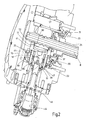
- the crown wheel 31 forms the drive-side part of the tool drive located in the interior of the tool disk 7. Whose details and the details of a clutch, which is located inside the tool disk, are from the Fig. 2 and 3 more clearly removable.
- a rotary body 35 is provided with a concentric to its axis of rotation shaft 37, which forms a rotary coupling part 39, with a tool-side coupling part for the rotary drive of a rotary tool, not shown, located at a tool station 45 in a tool holder 44 is located.
- the rotary body 35 forms an outer toothed rim 41 which concentrically surrounds the axis of rotation and engages with the toothing 43 of the crown wheel 31.
- the toothing 43 on the ring gear 31 has in a radial plane an extension which is selected so that the ring gear 41 with the teeth 43 is permanently engaged, regardless of whether the rotary body 35 by radial displacement movement in one of the first switching position or one of the second Switching position of the clutch corresponding position is set radially.
- the Fig. 1 and 2 show each one the rotational body 35, ie the output-side gear part of the tool drive, in the first switching position of the clutch corresponding radial position, while Fig. 3 the rotational body 35 in the second switching position of the clutch corresponding radial adjustment position shows. In both positions of the ring gear 41 is in meshing with the teeth 43 of the crown wheel 31st
- the clutch itself has, as between the first and second switching position radially movable coupling part on a bushing 47 concentrically surrounds the shaft 37 of the rotary body 35 and roller bearings 49 forms a rotary bearing of the output side gear part forming rotary body 35.
- the bush 47 has at the remote from the turret axis 13 rolling bearings 49 a shaft retaining ring 51 through which the bushing 47 in a radially outwardly directed displacement movement in the first switching position the rotational body 35 entrains.
- the actuation of the clutch takes place hydraulically.
- the bushing 47 on the outer peripheral side has a projecting annular body 53, which acts as an annular piston, which is guided in an annular guide section 55 and therein a separating element between a first pressure chamber 57 (FIGS. Fig. 1 and 2 ) and a second pressure chamber 59 (FIG. Fig. 3 ).
- the guide section 55 is guided for the pivoting movements about the turret axis 13 on a guide body 61 in the tool disk 7.
- the Fig. 1 and 2 show the clutch in the first switching position, in which the pressure chamber 57 is supplied with a hydraulic pressure medium, so that the bush 47 has moved radially outward into a position, at the end-side driver 63, the bushing 47 lock on driving surfaces 65 of the tool disk 7.
- this switching position serving as the output side gear member rotating body 35 is moved radially away with its sprocket 41 of the support column 11, but remains with its sprocket 41 with the teeth 43 of the crown gear 31 in mesh, so that a recorded in the tool holder 44 rotary tool is driven.
- a machining operation can therefore be carried out with the relevant rotary tool, regardless of the rotational position in which the tool station 45, at which the tool holder 44 of the respective rotary tool is located, is adjusted by rotating the tool disk 7.
- the Fig. 3 shows the positions corresponding to the second switching position of the clutch, now the other pressure chamber 59 is supplied with hydraulic pressure fluid, so that the serving as an annular piston ring body 53 of the bushing 47 and thus this moves itself radially inward.
- the drivers 63 of the bushing 47 are retracted from the driver surfaces 65 of the tool disk 7. Pivoting movements of the same about the turret axis 13 therefore lead to no entrainment of the rotary body 35, which forms the output-side gear part of the tool drive.
- the tool drive therefore remains in a given position regardless of the setting rotational movements of the tool disk 7.
- the guide body 61 is fixed securely in the adjustment rotational movement of the tool disk 7 in its angular position with respect to the turret axis 13, the rotational body 35 in the pushed inward position, ie the second switching position of the clutch, in a defined starting position, ie in a for the operation of a rotary tool preferred position, be set. This is done in such a way that at the pushed inward position a flattened portion 71 of the rotating body 35 presses through a passage 69 of the guide body 61 through flattened end portions 72 of the support column 11 and thus fixed to the support column 11 against rotation.
Landscapes
- Engineering & Computer Science (AREA)
- Mechanical Engineering (AREA)
- Cutting Tools, Boring Holders, And Turrets (AREA)
- Automatic Tool Replacement In Machine Tools (AREA)
- Turning (AREA)
- Gripping On Spindles (AREA)
Applications Claiming Priority (1)
| Application Number | Priority Date | Filing Date | Title |
|---|---|---|---|
| DE102008045181A DE102008045181B3 (de) | 2008-08-30 | 2008-08-30 | Werkzeugrevolver |
Publications (3)
| Publication Number | Publication Date |
|---|---|
| EP2158998A2 true EP2158998A2 (fr) | 2010-03-03 |
| EP2158998A3 EP2158998A3 (fr) | 2010-04-07 |
| EP2158998B1 EP2158998B1 (fr) | 2010-12-01 |
Family
ID=41396958
Family Applications (1)
| Application Number | Title | Priority Date | Filing Date |
|---|---|---|---|
| EP09008830A Not-in-force EP2158998B1 (fr) | 2008-08-30 | 2009-07-07 | Tourelle revolver |
Country Status (4)
| Country | Link |
|---|---|
| US (1) | US8561273B2 (fr) |
| EP (1) | EP2158998B1 (fr) |
| AT (1) | ATE490049T1 (fr) |
| DE (2) | DE102008045181B3 (fr) |
Families Citing this family (8)
| Publication number | Priority date | Publication date | Assignee | Title |
|---|---|---|---|---|
| DE102009042772A1 (de) * | 2009-09-25 | 2011-07-14 | Sauter Feinmechanik GmbH, 72555 | Antriebsvorrichtung |
| DE102012002695B4 (de) † | 2012-02-14 | 2024-08-01 | Zf Cv Systems Hannover Gmbh | Verfahren zur Ermittlung einer Notbremssituation eines Fahrzeuges |
| JP6182109B2 (ja) * | 2014-06-05 | 2017-08-16 | 株式会社村谷機械製作所 | ホーニング加工装置 |
| DE102014221418B4 (de) * | 2014-10-22 | 2020-10-29 | Supfina Grieshaber Gmbh & Co. Kg | Werkzeugmaschine zur Oberflächenbearbeitung eines Werkstücks |
| CN110548890A (zh) * | 2018-06-04 | 2019-12-10 | 鸿鼎科技有限公司 | 三孔钻夹头成型装置及成型方法 |
| EP3871812A1 (fr) * | 2020-02-28 | 2021-09-01 | Gildemeister Italiana S.r.l. | Unité de tourelle dotée d'un axe b et d'une machine-outil, en particulier un tour |
| CN113084566B (zh) * | 2021-04-30 | 2022-04-29 | 扬州鼎准科技有限责任公司 | 一种轴径向复合多刀杆动力刀架 |
| DE102023003464A1 (de) | 2023-08-23 | 2025-02-27 | Kolibri Beteiligungsgesellschaft Mbh & Co. Kgaa | Werkzeugrevolver |
Citations (4)
| Publication number | Priority date | Publication date | Assignee | Title |
|---|---|---|---|---|
| DE2849167B2 (de) | 1978-11-13 | 1980-12-11 | Gildemeister Ag, 4800 Bielefeld | Werkzeugrevolver |
| DE3929803C1 (fr) | 1989-09-07 | 1991-01-24 | Traub Ag, 7313 Reichenbach, De | |
| DE68908208T2 (de) | 1988-03-04 | 1994-03-31 | Duplomatic | Werkzeugrevolver für Drehmaschinen, Bearbeitungsinseln zum Drehen und ähnliche Vorrichtungen. |
| DE102005033890A1 (de) | 2005-07-20 | 2007-01-25 | Sauter Feinmechanik Gmbh | Werkzeugrevolver |
Family Cites Families (4)
| Publication number | Priority date | Publication date | Assignee | Title |
|---|---|---|---|---|
| DE3216891A1 (de) * | 1982-05-06 | 1983-11-10 | Index-Werke Kg Hahn & Tessky, 7300 Esslingen | Mehrspindel-revolerverdrehautomat |
| JPS6034239A (ja) * | 1983-07-30 | 1985-02-21 | Miyano Tekkosho:Kk | 工作機械における回転工具の駆動装置 |
| JP2003071615A (ja) * | 2001-08-30 | 2003-03-12 | Mori Seiki Co Ltd | タレット刃物台 |
| JP4251630B2 (ja) * | 2003-12-17 | 2009-04-08 | 株式会社森精機製作所 | 工作機械のタレット |
-
2008
- 2008-08-30 DE DE102008045181A patent/DE102008045181B3/de not_active Expired - Fee Related
-
2009
- 2009-07-07 AT AT09008830T patent/ATE490049T1/de active
- 2009-07-07 DE DE502009000216T patent/DE502009000216D1/de active Active
- 2009-07-07 EP EP09008830A patent/EP2158998B1/fr not_active Not-in-force
- 2009-08-13 US US12/461,518 patent/US8561273B2/en not_active Expired - Fee Related
Patent Citations (4)
| Publication number | Priority date | Publication date | Assignee | Title |
|---|---|---|---|---|
| DE2849167B2 (de) | 1978-11-13 | 1980-12-11 | Gildemeister Ag, 4800 Bielefeld | Werkzeugrevolver |
| DE68908208T2 (de) | 1988-03-04 | 1994-03-31 | Duplomatic | Werkzeugrevolver für Drehmaschinen, Bearbeitungsinseln zum Drehen und ähnliche Vorrichtungen. |
| DE3929803C1 (fr) | 1989-09-07 | 1991-01-24 | Traub Ag, 7313 Reichenbach, De | |
| DE102005033890A1 (de) | 2005-07-20 | 2007-01-25 | Sauter Feinmechanik Gmbh | Werkzeugrevolver |
Also Published As
| Publication number | Publication date |
|---|---|
| DE102008045181B3 (de) | 2010-01-07 |
| DE502009000216D1 (de) | 2011-01-13 |
| ATE490049T1 (de) | 2010-12-15 |
| US20100056351A1 (en) | 2010-03-04 |
| EP2158998B1 (fr) | 2010-12-01 |
| US8561273B2 (en) | 2013-10-22 |
| EP2158998A3 (fr) | 2010-04-07 |
Similar Documents
| Publication | Publication Date | Title |
|---|---|---|
| EP2158998B1 (fr) | Tourelle revolver | |
| DE60201794T2 (de) | Revolverwerkzeughalter | |
| DE102010035150B4 (de) | Automatisiert koppelbares Spannfutter | |
| DE69208199T2 (de) | Universalwerkzeugverbindung | |
| EP2517811B1 (fr) | Dispositif de forage | |
| EP2358502B1 (fr) | Engrenage planétaire commutable dans une machine-outil portative | |
| EP0461357B1 (fr) | Tourelle révolver porte outil | |
| DE19951658A1 (de) | Werkzeughalter | |
| EP2480372B1 (fr) | Dispositif d'entraînement | |
| DE3010934C2 (fr) | ||
| DE202017102598U1 (de) | Drehmomentausgangswerkzeug | |
| DE102015002232A1 (de) | Werkzeugrevolver | |
| EP0245629B1 (fr) | Dispositif de fixation de porte-pièces mécaniques aux broches des machines à tourner, en particulier de mandrins de serrage | |
| EP2185318B1 (fr) | Tourelle revolver | |
| EP1128930B1 (fr) | Tete d'outil a logement de broche | |
| DE202011001868U1 (de) | Werkzeugwechsler | |
| DE10164722A1 (de) | Werkzeug | |
| DE4235095A1 (de) | Werkzeugrevolver | |
| EP1163976A1 (fr) | Entrainement avec une transmission variable pour un dispositif porte outil | |
| DE20312887U1 (de) | Beim Betrieb rotierendes Werkzeug mit einem Werkzeugschaft | |
| EP2180979B1 (fr) | Outil à main électrique | |
| EP0545006A1 (fr) | Porte-outil revolver | |
| EP2602054B1 (fr) | Machine-outil | |
| EP1211017A1 (fr) | Broche tournante de machine outil montée dans un boitier | |
| EP3072634B1 (fr) | Tourelle revolver |
Legal Events
| Date | Code | Title | Description |
|---|---|---|---|
| PUAI | Public reference made under article 153(3) epc to a published international application that has entered the european phase |
Free format text: ORIGINAL CODE: 0009012 |
|
| AK | Designated contracting states |
Kind code of ref document: A2 Designated state(s): AT BE BG CH CY CZ DE DK EE ES FI FR GB GR HR HU IE IS IT LI LT LU LV MC MK MT NL NO PL PT RO SE SI SK SM TR |
|
| AX | Request for extension of the european patent |
Extension state: AL BA RS |
|
| PUAL | Search report despatched |
Free format text: ORIGINAL CODE: 0009013 |
|
| AK | Designated contracting states |
Kind code of ref document: A3 Designated state(s): AT BE BG CH CY CZ DE DK EE ES FI FR GB GR HR HU IE IS IT LI LT LU LV MC MK MT NL NO PL PT RO SE SI SK SM TR |
|
| AX | Request for extension of the european patent |
Extension state: AL BA RS |
|
| RIC1 | Information provided on ipc code assigned before grant |
Ipc: B23B 29/24 20060101ALI20100301BHEP Ipc: B23Q 5/04 20060101AFI20091229BHEP |
|
| 17P | Request for examination filed |
Effective date: 20100422 |
|
| GRAP | Despatch of communication of intention to grant a patent |
Free format text: ORIGINAL CODE: EPIDOSNIGR1 |
|
| GRAS | Grant fee paid |
Free format text: ORIGINAL CODE: EPIDOSNIGR3 |
|
| GRAA | (expected) grant |
Free format text: ORIGINAL CODE: 0009210 |
|
| AK | Designated contracting states |
Kind code of ref document: B1 Designated state(s): AT BE BG CH CY CZ DE DK EE ES FI FR GB GR HR HU IE IS IT LI LT LU LV MC MK MT NL NO PL PT RO SE SI SK SM TR |
|
| REG | Reference to a national code |
Ref country code: GB Ref legal event code: FG4D Free format text: NOT ENGLISH |
|
| REG | Reference to a national code |
Ref country code: CH Ref legal event code: EP |
|
| REG | Reference to a national code |
Ref country code: IE Ref legal event code: FG4D |
|
| REF | Corresponds to: |
Ref document number: 502009000216 Country of ref document: DE Date of ref document: 20110113 Kind code of ref document: P |
|
| REG | Reference to a national code |
Ref country code: NL Ref legal event code: VDEP Effective date: 20101201 |
|
| PG25 | Lapsed in a contracting state [announced via postgrant information from national office to epo] |
Ref country code: NO Free format text: LAPSE BECAUSE OF FAILURE TO SUBMIT A TRANSLATION OF THE DESCRIPTION OR TO PAY THE FEE WITHIN THE PRESCRIBED TIME-LIMIT Effective date: 20110301 Ref country code: LT Free format text: LAPSE BECAUSE OF FAILURE TO SUBMIT A TRANSLATION OF THE DESCRIPTION OR TO PAY THE FEE WITHIN THE PRESCRIBED TIME-LIMIT Effective date: 20101201 |
|
| LTIE | Lt: invalidation of european patent or patent extension |
Effective date: 20101201 |
|
| PG25 | Lapsed in a contracting state [announced via postgrant information from national office to epo] |
Ref country code: CY Free format text: LAPSE BECAUSE OF FAILURE TO SUBMIT A TRANSLATION OF THE DESCRIPTION OR TO PAY THE FEE WITHIN THE PRESCRIBED TIME-LIMIT Effective date: 20101201 Ref country code: HR Free format text: LAPSE BECAUSE OF FAILURE TO SUBMIT A TRANSLATION OF THE DESCRIPTION OR TO PAY THE FEE WITHIN THE PRESCRIBED TIME-LIMIT Effective date: 20101201 Ref country code: NL Free format text: LAPSE BECAUSE OF FAILURE TO SUBMIT A TRANSLATION OF THE DESCRIPTION OR TO PAY THE FEE WITHIN THE PRESCRIBED TIME-LIMIT Effective date: 20101201 Ref country code: LV Free format text: LAPSE BECAUSE OF FAILURE TO SUBMIT A TRANSLATION OF THE DESCRIPTION OR TO PAY THE FEE WITHIN THE PRESCRIBED TIME-LIMIT Effective date: 20101201 Ref country code: FI Free format text: LAPSE BECAUSE OF FAILURE TO SUBMIT A TRANSLATION OF THE DESCRIPTION OR TO PAY THE FEE WITHIN THE PRESCRIBED TIME-LIMIT Effective date: 20101201 Ref country code: SI Free format text: LAPSE BECAUSE OF FAILURE TO SUBMIT A TRANSLATION OF THE DESCRIPTION OR TO PAY THE FEE WITHIN THE PRESCRIBED TIME-LIMIT Effective date: 20101201 Ref country code: BG Free format text: LAPSE BECAUSE OF FAILURE TO SUBMIT A TRANSLATION OF THE DESCRIPTION OR TO PAY THE FEE WITHIN THE PRESCRIBED TIME-LIMIT Effective date: 20110301 Ref country code: SE Free format text: LAPSE BECAUSE OF FAILURE TO SUBMIT A TRANSLATION OF THE DESCRIPTION OR TO PAY THE FEE WITHIN THE PRESCRIBED TIME-LIMIT Effective date: 20101201 |
|
| REG | Reference to a national code |
Ref country code: IE Ref legal event code: FD4D |
|
| PG25 | Lapsed in a contracting state [announced via postgrant information from national office to epo] |
Ref country code: GR Free format text: LAPSE BECAUSE OF FAILURE TO SUBMIT A TRANSLATION OF THE DESCRIPTION OR TO PAY THE FEE WITHIN THE PRESCRIBED TIME-LIMIT Effective date: 20110302 |
|
| PG25 | Lapsed in a contracting state [announced via postgrant information from national office to epo] |
Ref country code: IE Free format text: LAPSE BECAUSE OF FAILURE TO SUBMIT A TRANSLATION OF THE DESCRIPTION OR TO PAY THE FEE WITHIN THE PRESCRIBED TIME-LIMIT Effective date: 20101201 Ref country code: PT Free format text: LAPSE BECAUSE OF FAILURE TO SUBMIT A TRANSLATION OF THE DESCRIPTION OR TO PAY THE FEE WITHIN THE PRESCRIBED TIME-LIMIT Effective date: 20110401 Ref country code: ES Free format text: LAPSE BECAUSE OF FAILURE TO SUBMIT A TRANSLATION OF THE DESCRIPTION OR TO PAY THE FEE WITHIN THE PRESCRIBED TIME-LIMIT Effective date: 20110312 Ref country code: IS Free format text: LAPSE BECAUSE OF FAILURE TO SUBMIT A TRANSLATION OF THE DESCRIPTION OR TO PAY THE FEE WITHIN THE PRESCRIBED TIME-LIMIT Effective date: 20110401 Ref country code: EE Free format text: LAPSE BECAUSE OF FAILURE TO SUBMIT A TRANSLATION OF THE DESCRIPTION OR TO PAY THE FEE WITHIN THE PRESCRIBED TIME-LIMIT Effective date: 20101201 Ref country code: CZ Free format text: LAPSE BECAUSE OF FAILURE TO SUBMIT A TRANSLATION OF THE DESCRIPTION OR TO PAY THE FEE WITHIN THE PRESCRIBED TIME-LIMIT Effective date: 20101201 |
|
| PG25 | Lapsed in a contracting state [announced via postgrant information from national office to epo] |
Ref country code: SK Free format text: LAPSE BECAUSE OF FAILURE TO SUBMIT A TRANSLATION OF THE DESCRIPTION OR TO PAY THE FEE WITHIN THE PRESCRIBED TIME-LIMIT Effective date: 20101201 Ref country code: PL Free format text: LAPSE BECAUSE OF FAILURE TO SUBMIT A TRANSLATION OF THE DESCRIPTION OR TO PAY THE FEE WITHIN THE PRESCRIBED TIME-LIMIT Effective date: 20101201 Ref country code: RO Free format text: LAPSE BECAUSE OF FAILURE TO SUBMIT A TRANSLATION OF THE DESCRIPTION OR TO PAY THE FEE WITHIN THE PRESCRIBED TIME-LIMIT Effective date: 20101201 |
|
| PLBE | No opposition filed within time limit |
Free format text: ORIGINAL CODE: 0009261 |
|
| STAA | Information on the status of an ep patent application or granted ep patent |
Free format text: STATUS: NO OPPOSITION FILED WITHIN TIME LIMIT |
|
| PG25 | Lapsed in a contracting state [announced via postgrant information from national office to epo] |
Ref country code: DK Free format text: LAPSE BECAUSE OF FAILURE TO SUBMIT A TRANSLATION OF THE DESCRIPTION OR TO PAY THE FEE WITHIN THE PRESCRIBED TIME-LIMIT Effective date: 20101201 |
|
| 26N | No opposition filed |
Effective date: 20110902 |
|
| REG | Reference to a national code |
Ref country code: DE Ref legal event code: R097 Ref document number: 502009000216 Country of ref document: DE Effective date: 20110902 |
|
| PG25 | Lapsed in a contracting state [announced via postgrant information from national office to epo] |
Ref country code: MT Free format text: LAPSE BECAUSE OF FAILURE TO SUBMIT A TRANSLATION OF THE DESCRIPTION OR TO PAY THE FEE WITHIN THE PRESCRIBED TIME-LIMIT Effective date: 20101201 |
|
| BERE | Be: lapsed |
Owner name: SAUTER FEINMECHANIK G.M.B.H. Effective date: 20110731 |
|
| PG25 | Lapsed in a contracting state [announced via postgrant information from national office to epo] |
Ref country code: MC Free format text: LAPSE BECAUSE OF NON-PAYMENT OF DUE FEES Effective date: 20110731 |
|
| REG | Reference to a national code |
Ref country code: FR Ref legal event code: ST Effective date: 20120330 |
|
| PG25 | Lapsed in a contracting state [announced via postgrant information from national office to epo] |
Ref country code: FR Free format text: LAPSE BECAUSE OF NON-PAYMENT OF DUE FEES Effective date: 20110801 Ref country code: BE Free format text: LAPSE BECAUSE OF NON-PAYMENT OF DUE FEES Effective date: 20110731 |
|
| PG25 | Lapsed in a contracting state [announced via postgrant information from national office to epo] |
Ref country code: MK Free format text: LAPSE BECAUSE OF FAILURE TO SUBMIT A TRANSLATION OF THE DESCRIPTION OR TO PAY THE FEE WITHIN THE PRESCRIBED TIME-LIMIT Effective date: 20101201 |
|
| PG25 | Lapsed in a contracting state [announced via postgrant information from national office to epo] |
Ref country code: SM Free format text: LAPSE BECAUSE OF FAILURE TO SUBMIT A TRANSLATION OF THE DESCRIPTION OR TO PAY THE FEE WITHIN THE PRESCRIBED TIME-LIMIT Effective date: 20101201 |
|
| PG25 | Lapsed in a contracting state [announced via postgrant information from national office to epo] |
Ref country code: LU Free format text: LAPSE BECAUSE OF NON-PAYMENT OF DUE FEES Effective date: 20110707 |
|
| PG25 | Lapsed in a contracting state [announced via postgrant information from national office to epo] |
Ref country code: TR Free format text: LAPSE BECAUSE OF FAILURE TO SUBMIT A TRANSLATION OF THE DESCRIPTION OR TO PAY THE FEE WITHIN THE PRESCRIBED TIME-LIMIT Effective date: 20101201 |
|
| PG25 | Lapsed in a contracting state [announced via postgrant information from national office to epo] |
Ref country code: HU Free format text: LAPSE BECAUSE OF FAILURE TO SUBMIT A TRANSLATION OF THE DESCRIPTION OR TO PAY THE FEE WITHIN THE PRESCRIBED TIME-LIMIT Effective date: 20101201 |
|
| REG | Reference to a national code |
Ref country code: CH Ref legal event code: PL |
|
| GBPC | Gb: european patent ceased through non-payment of renewal fee |
Effective date: 20130707 |
|
| PG25 | Lapsed in a contracting state [announced via postgrant information from national office to epo] |
Ref country code: GB Free format text: LAPSE BECAUSE OF NON-PAYMENT OF DUE FEES Effective date: 20130707 Ref country code: LI Free format text: LAPSE BECAUSE OF NON-PAYMENT OF DUE FEES Effective date: 20130731 Ref country code: CH Free format text: LAPSE BECAUSE OF NON-PAYMENT OF DUE FEES Effective date: 20130731 |
|
| REG | Reference to a national code |
Ref country code: AT Ref legal event code: MM01 Ref document number: 490049 Country of ref document: AT Kind code of ref document: T Effective date: 20140707 |
|
| PG25 | Lapsed in a contracting state [announced via postgrant information from national office to epo] |
Ref country code: AT Free format text: LAPSE BECAUSE OF NON-PAYMENT OF DUE FEES Effective date: 20140707 |
|
| PGFP | Annual fee paid to national office [announced via postgrant information from national office to epo] |
Ref country code: IT Payment date: 20190705 Year of fee payment: 11 Ref country code: DE Payment date: 20190731 Year of fee payment: 11 |
|
| REG | Reference to a national code |
Ref country code: DE Ref legal event code: R119 Ref document number: 502009000216 Country of ref document: DE |
|
| PG25 | Lapsed in a contracting state [announced via postgrant information from national office to epo] |
Ref country code: DE Free format text: LAPSE BECAUSE OF NON-PAYMENT OF DUE FEES Effective date: 20210202 |
|
| PG25 | Lapsed in a contracting state [announced via postgrant information from national office to epo] |
Ref country code: IT Free format text: LAPSE BECAUSE OF NON-PAYMENT OF DUE FEES Effective date: 20200707 |