EP2159008A2 - Outil d'impact - Google Patents
Outil d'impact Download PDFInfo
- Publication number
- EP2159008A2 EP2159008A2 EP09011068A EP09011068A EP2159008A2 EP 2159008 A2 EP2159008 A2 EP 2159008A2 EP 09011068 A EP09011068 A EP 09011068A EP 09011068 A EP09011068 A EP 09011068A EP 2159008 A2 EP2159008 A2 EP 2159008A2
- Authority
- EP
- European Patent Office
- Prior art keywords
- swinging
- air chamber
- dynamic vibration
- weight
- hammer
- Prior art date
- Legal status (The legal status is an assumption and is not a legal conclusion. Google has not performed a legal analysis and makes no representation as to the accuracy of the status listed.)
- Granted
Links
Images


Classifications
-
- B—PERFORMING OPERATIONS; TRANSPORTING
- B25—HAND TOOLS; PORTABLE POWER-DRIVEN TOOLS; MANIPULATORS
- B25D—PERCUSSIVE TOOLS
- B25D17/00—Details of, or accessories for, portable power-driven percussive tools
- B25D17/24—Damping the reaction force
-
- B—PERFORMING OPERATIONS; TRANSPORTING
- B25—HAND TOOLS; PORTABLE POWER-DRIVEN TOOLS; MANIPULATORS
- B25D—PERCUSSIVE TOOLS
- B25D16/00—Portable percussive machines with superimposed rotation, the rotational movement of the output shaft of a motor being modified to generate axial impacts on the tool bit
-
- B—PERFORMING OPERATIONS; TRANSPORTING
- B25—HAND TOOLS; PORTABLE POWER-DRIVEN TOOLS; MANIPULATORS
- B25D—PERCUSSIVE TOOLS
- B25D17/00—Details of, or accessories for, portable power-driven percussive tools
- B25D17/06—Hammer pistons; Anvils ; Guide-sleeves for pistons
-
- B—PERFORMING OPERATIONS; TRANSPORTING
- B25—HAND TOOLS; PORTABLE POWER-DRIVEN TOOLS; MANIPULATORS
- B25D—PERCUSSIVE TOOLS
- B25D2211/00—Details of portable percussive tools with electromotor or other motor drive
- B25D2211/06—Means for driving the impulse member
- B25D2211/061—Swash-plate actuated impulse-driving mechanisms
-
- B—PERFORMING OPERATIONS; TRANSPORTING
- B25—HAND TOOLS; PORTABLE POWER-DRIVEN TOOLS; MANIPULATORS
- B25D—PERCUSSIVE TOOLS
- B25D2217/00—Details of, or accessories for, portable power-driven percussive tools
- B25D2217/0073—Arrangements for damping of the reaction force
- B25D2217/0076—Arrangements for damping of the reaction force by use of counterweights
- B25D2217/0084—Arrangements for damping of the reaction force by use of counterweights being fluid-driven
-
- B—PERFORMING OPERATIONS; TRANSPORTING
- B25—HAND TOOLS; PORTABLE POWER-DRIVEN TOOLS; MANIPULATORS
- B25D—PERCUSSIVE TOOLS
- B25D2217/00—Details of, or accessories for, portable power-driven percussive tools
- B25D2217/0073—Arrangements for damping of the reaction force
- B25D2217/0076—Arrangements for damping of the reaction force by use of counterweights
- B25D2217/0092—Arrangements for damping of the reaction force by use of counterweights being spring-mounted
-
- B—PERFORMING OPERATIONS; TRANSPORTING
- B25—HAND TOOLS; PORTABLE POWER-DRIVEN TOOLS; MANIPULATORS
- B25D—PERCUSSIVE TOOLS
- B25D2222/00—Materials of the tool or the workpiece
- B25D2222/54—Plastics
-
- B—PERFORMING OPERATIONS; TRANSPORTING
- B25—HAND TOOLS; PORTABLE POWER-DRIVEN TOOLS; MANIPULATORS
- B25D—PERCUSSIVE TOOLS
- B25D2250/00—General details of portable percussive tools; Components used in portable percussive tools
- B25D2250/121—Housing details
-
- B—PERFORMING OPERATIONS; TRANSPORTING
- B25—HAND TOOLS; PORTABLE POWER-DRIVEN TOOLS; MANIPULATORS
- B25D—PERCUSSIVE TOOLS
- B25D2250/00—General details of portable percussive tools; Components used in portable percussive tools
- B25D2250/245—Spatial arrangement of components of the tool relative to each other
Definitions
- the invention relates to a vibration reducing technique for an impact tool which linearly drives a tool bit by means of a swinging member.
- Japanese non-examined laid-open Patent Publication No. 2008-73836 discloses an electric hammer drill that drives a hammer bit by using a swinging mechanism (also referred to as "swash mechanism").
- the kwon art includes a vibration reducing mechanism having a dynamic vibration reducer mounted to a tool body of the hammer drill.
- the dynamic vibration reducer is designed to actively drive or forcibly vibrate a weight of the dynamic vibration reducer by directly utilizing swinging movement of a swinging member in the form of the swinging ring and thereby reduce vibration caused during hammering operation.
- the dynamic vibration reducer can be steadily operated.
- the known vibration reducing mechanism is of the mechanical type that vibrates the dynamic vibration reducer by using machine parts directly operated by swinging movement of the swinging ring. Therefore, the number of machine parts relating to such vibration increase and it is necessary to move the weight of the dynamic vibration reducer in a direction opposite to the direction of movement of the hammer bit. Due to these facts, a vibration mechanism section has to be disposed on the opposite side of the center of swinging movement from a hammer bit driving mechanism section and is thus difficult to dispose by utilizing a free space within the tool body. Therefore, in these respects, further improvement is required.
- a representative impact tool to perform a hammering operation by linearly driving a tool bit at least in an axial direction of the tool bit.
- the representative impact tool includes a motor, a swinging member that swings in the axial direction of the tool bit by rotation of the motor, a driving element that reciprocates by a swinging movement of the swinging member and a first air chamber in which pressure is fluctuated by reciprocating movement of the driving element and the tool bit is driven by pressure fluctuations of the first air chamber.
- the impact tool further includes a second air chamber in which pressure is fluctuated by swinging movement of the swinging member and a dynamic vibration reducer having a weight and an elastic element that exerts a biasing force on the weight. The weight under the biasing force of the elastic element is forcibly vibrated by pressure fluctuations of the second air chamber.
- the second air chamber may be provided in which pressure is fluctuated by a swinging movement of the swinging member, and the weight of the dynamic vibration reducer is forcibly vibrated by pressure fluctuations of the second air chamber.
- the weight is vibrated by utilizing fluctuations of air pressure
- the number of machine parts can be reduced compared with a mechanical vibration mechanism.
- the system of pneumatic vibration by pressure fluctuations of air it can be constructed such that the second air chamber and the dynamic vibration reducer are connected by a passage, so that constraints on the installation place for the second air chamber can be lessened. Therefore, the second air chamber can be easily formed by utilizing a free space existing around the swinging member.
- a rational pneumatic vibration mechanism can be realized by utilizing the free space.
- the impact tool may have a driving member mounted to the swinging member to fluctuate pressure in the second air chamber.
- the driving member and the driving element are disposed on the opposite sides of the swinging member.
- the driving element is disposed on one side of the swinging member in the swinging direction, but a free space exists on the other side of the swinging member in the swinging direction.
- the second air chamber and the driving member can be rationally installed by utilizing this free space.
- the weight of the dynamic vibration reducer can be moved in a direction opposite to the tool bit.
- the driving member and the driving element are coaxially disposed.
- the driving member and the driving element are linearly driven by swinging movement of the swinging member and air of the second air chamber or the first air chamber is compressed, a reaction force caused by this compression is transmitted from the driving member to the driving element or from the driving element to the driving member via the swinging member.
- the reaction force is transmitted along the same axis, so that useless stress which, for example, may cause a twist is not easily generated on the swinging member, so that durability can be effectively enhanced.
- the driving member and the driving element are integrally formed with each other.
- the number of parts can be reduced, which leads to improvement in ease of assembling operation.
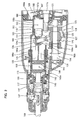
- FIG. 1 is a sectional side view showing an entire electric hammer drill 101 as a representative embodiment of the impact tool according to the invention.
- FIG. 2 is an enlarged sectional view showing an essential part of the hammer drill 101.
- the hammer drill 101 mainly includes a body 103 that forms an outer shell of the hammer drill 101 and an elongate hammer bit 119 that is detachably coupled to one end (left end as viewed in FIG. 1 ) of the body 103 in a longitudinal direction of the hammer drill 101.
- the body 103 is provided as a component part for forming a tool body.
- the hammer bit 119 is held by the tool holder 137 such that it is allowed to reciprocate with respect to the tool holder 137 in its axial direction (in the longitudinal direction of the body 103) and prevented from rotating with respect to the tool holder 13 7 in its circumferential direction.
- the hammer bit 119 is a feature that corresponds to the "tool bit" according to the invention.
- the body 103 includes a motor housing 105 that houses a driving motor 111, a gear housing 107 that houses a motion converting section 113, a power transmitting section 114 and a striking mechanism 115, and a handgrip 109 that is connected to the other end (right end as viewed in FIG. 1 ) of the body 103 in the axial direction of the hammer drill 101 and designed to be held by a user.
- the driving motor 111 is driven when a user depresses a trigger 109a disposed on the handgrip 109.
- the side of the hammer bit 119 is taken as the front or tool front side, and the side of the handgrip 109 as the rear or tool rear side.
- FIG. 2 shows the motion converting section 113, the power transmitting section 114 and the striking mechanism 115 in enlarged sectional view.
- the motion converting section 113 serves to convert the rotating output of the driving motor 111 into linear motion and then transmit it to the striking mechanism 115. Then, a striking force (impact force) is generated in the axial direction of the hammer bit 119 via the striking mechanism 115.
- the motion converting section 113 mainly includes a driving gear 121, a driven gear 123, a driven shaft 125, a rotating element 127, a swinging ring 129 and a piston 141.
- the driving gear 121 is connected to a motor output shaft 111a of the driving motor 111 that extends in the axial direction of the hammer bit 119 and rotationally driven when the driving motor 111 is driven.
- the driven gear 123 engages with the driving gear 121 and the driven shaft 125 is mounted to the driven gear 123. Therefore, the driven shaft 125 is connected to the motor output shaft 111a of the driving motor 111 and rotationally driven.
- the driving motor 111 is a feature that corresponds to the "motor" according to the invention.
- the rotating element 127 rotates together with the driven gear 123 via the driven shaft 125.
- the outer periphery of the rotating element 127 fitted onto the driven shaft 125 is inclined at a predetermined inclination with respect to the axis of the driven shaft 125.
- the swinging ring 129 is rotatably mounted on the inclined outer periphery of the rotating element 127 via a bearing 126 and caused to swing in the axial direction of the hammer bit 119 by rotation of the rotating element 127.
- the swinging ring 129 is a feature that corresponds to the "swinging member" according to the invention.
- the swinging ring 129 has a swinging rod 128 extending upward (in the radial direction) therefrom in a direction transverse to the axial direction of the hammer bit 119, and the swinging rod 128 is connected to the piston 141 via a ball (steel ball) 124 such that the swinging rod 128 can pivot in all directions.
- the piston 141 is caused to reciprocate in the axial direction of the hammer bit within a cylindrical hammer 143 having a bottom by swinging movement of the swinging ring 129, and serves as a driving element for driving the striking mechanism 115.
- the piston 141 is a feature that corresponds to the "driving element" according to this invention.
- the motor output shaft 111a of the driving motor 111, the driven shaft 125 and the piston 141 each extend in the axial direction of the hammer bit 119 and are disposed in parallel to each other.
- the driven shaft 125 is disposed below the motor output shaft 111a of the driving motor 111 and the piston 141 is disposed above the driven shaft 125.
- the power transmitting section 114 serves to appropriately reduce the speed of the rotating output of the driving motor 111 and transmit it to the hammer bit 119 so that the hammer bit 119 is caused to rotate in its circumferential direction.
- the power transmitting section 114 is disposed to the hammer bit 119 side of the driving motor 111 in the axial direction of the hammer bit 119.
- the power transmitting section 114 according to this embodiment mainly includes a first transmission gear 131, a second transmission gear 133, a hammer guide 139 and a tool holder 137.
- the first transmission gear 131 is caused to rotate in a vertical plane by the driving motor 111 via the driving gear 121 and the driven shaft 125.
- the second transmission gear 133 is engaged with the first transmission gear 131 and rotates the tool holder 137 on its axis when the driven shaft 125 rotates.
- the hammer guide 139 extends in the axial direction of the hammer bit 119 and serves to guide linear movement of the hammer 143. Further, the hammer guide 139 is configured as a cylindrical element that is rotated together with the second transmission gear 133.
- the tool holder 137 extends in the axial direction of the hammer bit 119 and serves as a holding element to hold the hammer bit 119. Further, the tool holder 137 is rotated together with the hammer guide 139 via a torque limiter 135.
- the tool holder 137 is rotatably supported via the bearing 147 by a cylindrical barrel 117 which is integrally formed on the front end of the gear housing 107. Further, the hammer guide 139 is rotatably supported via a bearing 126 by a cylindrical guide holding portion 108a which is formed on an inner housing 108 within the gear housing 107.
- the striking mechanism 115 mainly includes the hammer 143 having a cylindrical shape with a bottom and fitted within the bore of the hammer guide 139 such that it can slide in the axial direction of the hammer bit, and an intermediate element in the form of an impact bolt 145 that is slidably fitted within the tool holder 137 and serves to transmit kinetic energy of the hammer 143 to the hammer bit 119.
- An air spring chamber 143a is defined by a bore inner wall of the hammer 143 and an axial front end surface of the piston 141 which is slidably fitted into the bore.
- the hammer 143 is configured as a striker that is caused to move forward via the air spring chamber 143a by linear movement of the piston 141 and strikes the hammer bit 119.
- the air spring chamber 143a is formed on an extension of the axis of the hammer bit 119.
- the air spring chamber 143a is a feature that corresponds to the "first air chamber" according to the invention.
- the driving gear 121 is caused to rotate in a vertical plane by the rotating output of the driving motor 111.
- the rotating element 127 is caused to rotate in a vertical plane via the driven gear 123 that is engaged with the driving gear 121, and the driven shaft 125, which in turn causes the swinging ring 129 and the swinging rod 128 to swing in the axial direction of the hammer bit 119.
- the piston 141 is caused to linearly slide by the swinging movement of the swinging rod 128.
- the hammer 143 By the action of the air spring function (pressure fluctuations) within the air spring chamber 143a as a result of this sliding movement of the piston 141, the hammer 143 linearly moves within the hammer guide 139. At this time, the hammer 143 collides with the impact bolt 145 and transmits the kinetic energy caused by the collision to the hammer bit 119.
- the hammer guide 139 When the first transmission gear 131 is caused to rotate together with the driven shaft 125, the hammer guide 139 is caused to rotate in a vertical plane via the second transmission gear 133 that is engaged with the first transmission gear 131, which in turn causes the tool holder 137 and the hammer bit 119 held by the tool holder 137 to rotate in the circumferential direction together with the hammer guide 139.
- the hammer bit 119 performs a hammering movement in the axial direction and a drilling movement in the circumferential direction, so that a hammer drill operation is performed on the workpiece.
- the hammer bit 119 is struck by the hammer 143 formed by a cylindrical member, and the piston 141 disposed within the hammer 143 is driven by the swinging ring 129. Therefore, in contrast to the known construction in which the piston driven by the swinging ring is formed, for example, by a cylindrical member and the striker disposed within the cylindrical piston strikes the hammer bit, the piston 141 can be shaped like a disk. As a result, the piston 141 can be reduced in its mass (weight), so that vibration caused in the hammer drill 101 can be effectively reduced. Further, the hammer 143 that houses the piston 141 has a cylindrical shape having a bottom and it structurally has a predetermined length in the axial direction of the hammer 143. Therefore, a physically rational construction is obtained by using a cylindrical member as the hammer 143 which requires weight.
- the piston 141 is made of resin. Therefore, when the hammer drill 101 is driven, the temperature within the air spring chamber 143a is elevated by compression of air, so that heat must be dissipated.
- a wall surface of the air spring chamber 143a is defmed by the hammer 143 which is a cylindrical member made of iron, so that the heat within the air spring chamber 143a is dissipated via the hammer 143. Therefore, as for the piston 141, it is not necessary to particularly consider the heat dissipating ability of the air spring chamber 143a.
- the piston 141 can be made of resin, so that weight reduction and cost reduction can be effectively realized.
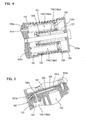
- FIG. 3 is a sectional view showing the sectional structure of the dynamic vibration reducer 151 and its surrounding members as viewed from the front of the hammer drill 101.
- FIG. 4 is a sectional view taken along line B-B in FIG. 3
- FIG. 5 is a sectional view taken along line A-A in FIG. 3 . As shown in FIGS.
- the dynamic vibration reducer 151 mainly includes a dynamic vibration reducer body 153, a weight 155 for vibration reduction, and front and rear coil springs 157 disposed on the tool front and rear sides of the weight 155 and extending in the axial direction of the hammer bit 119.
- the dynamic vibration reducer 151 is a feature that corresponds to the "dynamic vibration reducer" according to the invention.
- the dynamic vibration reducer body 153 has a housing space for housing the weight 155 and the coil spring 157 and is provided as a cylindrical guide for guiding the weight 155 to slide with stability.
- the dynamic vibration reducer body 153 is fixedly mounted to the body 103.
- the weight 155 is configured as a mass part which is slidably disposed within the housing space of the dynamic vibration reducer body 153 in such a manner as to move in the longitudinal direction of the housing space (in the axial direction of the hammer bit 119).
- the weight 155 is a feature that corresponds to the "weight” according to the invention.
- the weight 155 has spring receiving spaces 156 having a circular section and extending in the form of a hollow in the axial direction of the hammer bit 119 over a predetermined region in the front and rear portions of the weight 155.
- One end of each of the coil springs 157 is received in the associated spring receiving space 156. In this embodiment, as shown in FIGS.
- three spring receiving spaces 156 are arranged in a vertical direction transverse to the axial direction of the hammer bit 119.
- One of the three spring receiving spaces 156 which are formed in the front portion of the weight 155 (the right region of the weight 155 as viewed in FIG. 4 ) is referred to as a first spring receiving space 156a, and the other two in the rear portion of the weight 155 (the left region of the weight 155 as viewed in FIG. 4 ) are referred to as second spring receiving spaces 156b.
- the first spring receiving space 156a receives the coil spring 157 disposed on the front of the weight 155, while the second spring receiving spaces 156b receive the coil springs 157 disposed on the rear of the weight 155.
- the coil springs 157 are configured as elastic elements which support the weight 155 with respect to the dynamic vibration reducer body 153 or the body 103 such that the coil springs 157 apply respective spring forces to the weight 155 toward each other when the weight 155 moves within the housing space of the dynamic vibration reducer body 153 in the longitudinal direction (in the axial direction of the hammer bit 119). Further, preferably, the total spring constant of the two coil springs 157 received in the second spring receiving spaces 156b is equal to the spring constant of the coil spring 157 received in the first spring receiving space 156a.
- the coil spring 157 is a feature that corresponds to the "elastic element" according to the invention.
- the front coil spring 157 received in the first spring receiving space 156a its front end is supported by a front wall part 153a of the dynamic vibration reducer body 153, and its rear end is supported by a spring receiver 158 disposed on the bottom of the first spring receiving space 156a.
- each of the rear coil springs 157 received in the second spring receiving spaces 156b its front end is supported by a spring receiver 159 disposed on the bottom of the second spring receiving space 156b, and its rear end is supported by a rear wall part 153b of the dynamic vibration reducer body 153.
- the front and rear coil springs 157 exert respective elastic biasing forces on the weight 155 toward each other in the axial direction of the hammer bit 119.
- the weight 155 can move in the axial direction of the hammer bit 119 in the state in which the elastic biasing forces of the front and rear coil springs 157 are exerted on the weight 155 toward each other.
- the weight 155 and the coil springs 157 serve as vibration reducing elements in the dynamic vibration reducer 151 and cooperate to passively reduce vibration of the body 103 during the operation of the hammer drill 101.
- the vibration of the body 103 in the hammer drill 101 can be alleviated during operation.
- the spring receiving spaces 156 are formed inside the weight 155 and one end of each of the coil springs 157 is disposed within the spring receiving space 156.
- the length of the dynamic vibration reducer 151 can be reduced in the axial direction of the hammer bit 119 with the coil springs 157 received and set in the spring receiving spaces 156 of the weight 155, so that the dynamic vibration reducer 151 can be reduced in size in the axial direction of the hammer bit 119.
- the first and second spring receiving spaces 156a, 156b of the spring receiving spaces 156 formed in the weight 155 are arranged to overlap to each other at predetermined region in a longitudinal direction.
- the coil spring 157 received in the first spring receiving space 156a and the coil springs 157 received in the second spring receiving spaces 156b are arranged to overlap to each other in a direction transverse to the extending direction of the coil springs.
- this construction is effective in further reducing the size of the dynamic vibration reducer 151 in its longitudinal direction and in reducing its weight with a simpler structure.
- this construction is particularly effective when installation space for the dynamic vibration reducer 151 within the body 103 is limited in the longitudinal direction of the body 103.
- the coil springs can be further upsized by the amount of the overlap between the coil spring 157 received in the first spring receiving space 156a and the coil springs 157 received in the second spring receiving spaces 156a, provided that the length of the dynamic vibration reducer in the longitudinal direction is not changed.
- the dynamic vibration reducer 151 can provide a higher vibration reducing effect by the upsized coil springs with stability.
- the dynamic vibration reducer 151 having the above-described construction is disposed in a left region (on the left side as viewed in FIG. 3 ) within the body 103 when the body 103 is viewed from the tool front (from the left as viewed in FIG. 2 ).
- the dynamic vibration reducer 151 is disposed within a left region of an interior space 110 of the gear housing 107 to the left of the motion converting section 113.
- a region around the motion converting section 113 is likely to be rendered free. Therefore, by installing the dynamic vibration reducer 151 within this region, rational placement of the dynamic vibration reducer 151 can be realized without increasing the size of the body 103 by effectively utilizing a free space within the body 103.
- a pneumatic vibration mechanism 161 which actively drives or forcibly vibrates the weight 155 of the dynamic vibration reducer 151 by utilizing fluctuations of air pressure.
- the pneumatic vibration mechanism 161 mainly includes an air chamber 163, a piston member 165 that fluctuates the pressure within the air chamber 163 and an air passage 167 that connects the air chamber 163 to the dynamic vibration reducer 151.
- the pneumatic vibration mechanism 161 is disposed by utilizing a rear region at the rear of the swinging ring 129 or particularly a rear region at the rear of the swinging rod 128 within the internal space 110 of the gear housing 107.
- an inner housing 108 is disposed in the rear of the gear housing 107 and has a vertical wall 108b in a direction transverse to the axis of the hammer bit 119 and a cylindrical portion 108c having an open front end and formed on the vertical wall 108b.
- the air chamber 163 is defined by an inner wall of the cylindrical portion 108c and a rear surface of the piston member 165.
- the piston member 165 is fitted into the cylindrical member 108c such that it can slide in the axial direction of the hammer bit 119.
- the air chamber 163 is formed on the extension of the axis of the hammer bit 119.
- the air chamber 163 is a feature that corresponds to the "second air chamber” according to the invention.
- the cylindrical portion 108c extends further forward over the swinging rod 128, and the cylindrical guide holding portion 108a is formed on the extending end of the cylindrical portion 108c.
- the cylindrical guide holding portion 108a has a larger diameter than the cylindrical portion 108c and serves to rotatably support the above-described hammer guide 139. Further, an opening 108d is formed in between the cylindrical portion 108c and the guide holding portion 108a in order to avoid interference with the swinging rod 128.
- the piston member 165 is coupled to the swinging rod 128 of the swinging ring 129 and caused to reciprocate within the air chamber 163 by swinging movement of the swinging ring 129.
- the piston member 165 is provided as a pressure fluctuating member to fluctuate the pressure within the air chamber 163.
- the piston member 165 is a feature that corresponds to the "driving member" according to the invention.
- the piston member 165 and the piston 141 are coaxially disposed on the opposite sides of the swinging rod 128 of the swinging ring 129.
- the piston member 165 is connected to an arm 142 that extends rearward from the rear surface of the piston 141.
- the arm 142 for connecting the piston member 165 and the piston 141 is connected to the swinging rod 128 via a spherical connecting structure.
- the spherical connecting structure includes a connection 166 having a concave spherical surface 166a formed on the arm 142 and a ball 124 fitted into the connection 166.
- the piston 141 and the piston member 165 are connected to the swinging rod 128 such that they are allowed to pivot in all directions with respect to the swinging rod 128 by sliding movement of the ball 124 in spherical contact with the connection 166.
- the swinging rod 128 is loosely fitted into a through hole 124a passing through the center of the ball 124 and formed through the ball 124, and allowed to slide with respect to the ball 124 along and around the longitudinal direction of the through hole 124a.
- the arm 142 and the swinging rod 128 are connected with each other via the ball 124, but a cylindrical element may be used in place of the ball 124.
- the piston 141 and the piston member 165 are integrally formed of resin together with the arm 142. Further, a circular opening 166b through which the ball 124 is fitted into the connection 166 is formed in the connection 166 of the arm 142. Thus, the ball 124 is mounted by fitting into the connection 166 through the circular opening 166b by utilizing flexibility of resin. Therefore, the connection 166 is not necessary to have a split structure, so that a rational spherical connecting structure can be realized.
- the piston member 165 has a cylindrical shape having an open front end and a closed rear end, and an outer surface of the rear end portion of the piston member 165 is held in sliding contact with the inner wall surface of the air chamber 163.
- the sliding performance of the piston 141 with respect to the hammer 143 can be ensured.
- the piston 141 that reciprocates within the hammer 143a may be acted upon by a force in a direction that twists the piston 141 (a force other than in its moving direction).
- sliding performance of the piston 141 with respect to the hammer 143 may be impaired.
- the piston member 165 that linearly moves to fluctuate pressure in the air chamber 163 is guided to slide in contact with the inner circumferential wall surface of the air chamber 163.
- the piston member 165 serves as a sliding guide for the piston 141.
- the piston member 165 forms a slider and the inner circumferential wall surface of the air chamber 163 (the inner circumferential surface of the cylindrical portion 108c) forms a sliding guide.
- the piston member 165 and the inner circumferential wall surface of the air chamber 163 form the "sliding guide" according to the invention.
- the sliding movement of the piston 141 is guided at two points to the both sides of the swinging ring 129 in the longitudinal direction by the hammer 143 and the cylindrical portion 108c of the inner housing 108 which is a component part of the air chamber 163. Therefore, the piston 141 is prevented from twisting with respect to the hammer 143, so that the piston 141 can obtain smooth and stable sliding performance.
- the air chamber 163 communicates with the rear second spring receiving space 156b of the dynamic vibration reducer 151 via the air passage 167.
- the air passage 167 includes a recessed groove 168 formed in the inner housing 108 and a groove cover 169 that covers the top of the recessed groove 168.
- the air passage 167 communicates at one end with the air chamber via a first communication hole 167a formed in the inner housing 108 and also communicates at the other end with the second spring receiving space 156b of the dynamic vibration reducer 151 via a second communication hole 167b formed in the inner housing 108 and the dynamic vibration reducer body 153.
- the recessed groove 168 is formed along the rear surface of the vertical wall 108b of the inner housing 108 and the groove cover 169 is mounted on the rear wall of the inner housing 108 by a screw 169a so as to cover the recessed groove 168. Further, the first spring receiving space 156a of the dynamic vibration reducer 151 communicates with the internal space 110 of the gear housing 107 via a vent hole 153c formed in the dynamic vibration reducer body 153.
- the pressure in the air chamber 163 fluctuates in relation to the driving of the motion converting section 113.
- the piston member 165 is caused to reciprocate within the air chamber 163 in the longitudinal direction by the swinging movement of the swinging ring 129 which is a component part of the motion converting section 113.
- the volume of the hermetically closed air chamber 163 is caused to fluctuate, so that the pressure in the air chamber 163 fluctuates.
- Air in the air chamber 163 is compressed (pressure is raised) by rearward movement of the piston member 165, while air in the air chamber 163 is expanded (pressure is reduced) by forward movement of the piston member 165.
- the dynamic vibration reducer 151 also serves as an active vibration reducing mechanism by forced vibration, so that it can effectively alleviate vibration caused in the body 103 in the longitudinal direction during hammering operation or hammer drill operation.
- the pneumatic vibration mechanism 161 for the dynamic vibration reducer 151 is provided by utilizing a rear region at the rear of the swinging ring 129 which is a component part of the motion converting section 113, or particularly a rear region at the rear of the swinging rod 128, within the internal space 110 of the gear housing 107.
- a region at the rear of the swinging ring 129 and above the motor output shaft 111a exists as a free space.
- the pneumatic vibration mechanism 161 can be rationally provided by effectively utilizing the free space within the body 103 without increasing the size of the body 103.
- the piston member 165 and the piston 141 are coaxially disposed.
- the piston member 165 and the piston 141 are operated by swinging movement of the swinging ring 129 and compress air in the air chamber 163 or air in the air spring chamber 143a, a reaction force caused by this compression is transmitted from the piston member 165 to the piston 141 or from the piston 141 to the piston member 165 via the swinging rod 128.
- the reaction force is transmitted along the same axis. Therefore, useless stress which, for example, may cause a twist is not easily generated on the swinging rod 128, so that the durability can be effectively improved.
- the piston member 165 and the piston 141 are integrally formed. With such a construction, the number of parts can be reduced, which leads to improvement in ease of assembling operation.
- the air passage 167 that connects the air chamber 163 of the pneumatic vibration mechanism 161 and the second spring receiving space 105b of the dynamic vibration reducer 151 is formed in the vertical wall 108b of the inner housing 108 within the gear housing 107. Therefore, in contrast, for example, to a construction in which such connection is made by using a pipe and a pipe connecting operation must be performed in a limited region within the gear housing 107, such a pipe connecting operation is not necessary and thus ease of assembling operation can be improved.
- the piston member 165 and the piston 141 are described as being coaxially disposed, but they may be disposed on different axes. Further, the piston 141 and the piston member 165 may be formed by separate members and individually connected to the swinging ring 129. Further, in this embodiment, the dynamic vibration reducer 151 is described as being disposed in a region to the left of the motion converting section 113 as viewed from the front of the hammer drill 101, but it may be disposed in regions other than the left region, for example, in a right region, both in the right and left regions or in an upper region. Further, the air passage 167 may be formed by piping.
- the hammer drill is explained as a representative example of the impact tool, but the invention can be applied to a hammer that performs a predetermined operation by linearly driving a tool bit.
- all features disclosed in the description and/or the claims are intended to be disclosed separately and independently from each other for the purpose of original disclosure as well as for the purpose of restricting the claimed invention independent of the composition of the features in the embodiments and/or the claims.
- all value ranges or indications of groups of entities disclose every possible intermediate value or intermediate entity for the purpose of original disclosure as well as for the purpose of restricting the claimed invention, in particular as limits of value ranges.
Landscapes
- Engineering & Computer Science (AREA)
- Mechanical Engineering (AREA)
- Percussive Tools And Related Accessories (AREA)
- Dental Tools And Instruments Or Auxiliary Dental Instruments (AREA)
- Electrophonic Musical Instruments (AREA)
Priority Applications (1)
| Application Number | Priority Date | Filing Date | Title |
|---|---|---|---|
| EP13174215.7A EP2674258B1 (fr) | 2008-08-29 | 2009-08-28 | Outil d'impact |
Applications Claiming Priority (1)
| Application Number | Priority Date | Filing Date | Title |
|---|---|---|---|
| JP2008222106A JP5290666B2 (ja) | 2008-08-29 | 2008-08-29 | 打撃工具 |
Related Child Applications (2)
| Application Number | Title | Priority Date | Filing Date |
|---|---|---|---|
| EP13174215.7A Division EP2674258B1 (fr) | 2008-08-29 | 2009-08-28 | Outil d'impact |
| EP13174215.7 Division-Into | 2013-06-28 |
Publications (3)
| Publication Number | Publication Date |
|---|---|
| EP2159008A2 true EP2159008A2 (fr) | 2010-03-03 |
| EP2159008A3 EP2159008A3 (fr) | 2011-03-23 |
| EP2159008B1 EP2159008B1 (fr) | 2013-08-14 |
Family
ID=41395449
Family Applications (2)
| Application Number | Title | Priority Date | Filing Date |
|---|---|---|---|
| EP09011068.5A Active EP2159008B1 (fr) | 2008-08-29 | 2009-08-28 | Outil d'impact |
| EP13174215.7A Active EP2674258B1 (fr) | 2008-08-29 | 2009-08-28 | Outil d'impact |
Family Applications After (1)
| Application Number | Title | Priority Date | Filing Date |
|---|---|---|---|
| EP13174215.7A Active EP2674258B1 (fr) | 2008-08-29 | 2009-08-28 | Outil d'impact |
Country Status (5)
| Country | Link |
|---|---|
| US (1) | US7967078B2 (fr) |
| EP (2) | EP2159008B1 (fr) |
| JP (1) | JP5290666B2 (fr) |
| CN (1) | CN101659049B (fr) |
| RU (1) | RU2510326C2 (fr) |
Cited By (3)
| Publication number | Priority date | Publication date | Assignee | Title |
|---|---|---|---|---|
| WO2011072916A1 (fr) * | 2009-12-16 | 2011-06-23 | Robert Bosch Gmbh | Machine-outil à main comportant un dispositif d'amortissement des vibrations |
| EP2425937A1 (fr) * | 2010-09-02 | 2012-03-07 | HILTI Aktiengesellschaft | Machine-outil à main |
| CN120314520A (zh) * | 2025-06-16 | 2025-07-15 | 陕西陕煤榆北煤业有限公司 | 一种地下矿井内用气体监测设备及方法 |
Families Citing this family (22)
| Publication number | Priority date | Publication date | Assignee | Title |
|---|---|---|---|---|
| US20090114412A1 (en) * | 2007-11-05 | 2009-05-07 | Black And Decker Inc. | Power tool having housing with enhanced impact resistance |
| JP5336781B2 (ja) * | 2008-07-07 | 2013-11-06 | 株式会社マキタ | 作業工具 |
| JP5361504B2 (ja) * | 2009-04-10 | 2013-12-04 | 株式会社マキタ | 打撃工具 |
| DE102011007433A1 (de) * | 2010-04-20 | 2011-12-08 | Robert Bosch Gmbh | Handwerkzeugmaschinenvorrichtung |
| WO2011153689A1 (fr) * | 2010-06-09 | 2011-12-15 | Bosch Power Tools (China) Co., Ltd. | Mécanisme de percussion |
| JP5496812B2 (ja) * | 2010-08-03 | 2014-05-21 | 株式会社マキタ | 作業工具 |
| US9156152B2 (en) * | 2011-08-31 | 2015-10-13 | Makita Corporation | Impact tool having counter weight that reduces vibration |
| DE102012210088A1 (de) * | 2012-06-15 | 2013-12-19 | Hilti Aktiengesellschaft | Werkzeugmaschine |
| EP3189940B1 (fr) * | 2012-12-25 | 2018-01-31 | Makita Corporation | Outil à impact |
| US9597784B2 (en) | 2013-08-12 | 2017-03-21 | Ingersoll-Rand Company | Impact tools |
| US9539715B2 (en) | 2014-01-16 | 2017-01-10 | Ingersoll-Rand Company | Controlled pivot impact tools |
| JP6348337B2 (ja) | 2014-05-16 | 2018-06-27 | 株式会社マキタ | 往復動式作業工具 |
| JP6278830B2 (ja) | 2014-05-16 | 2018-02-14 | 株式会社マキタ | 打撃工具 |
| JP6441588B2 (ja) * | 2014-05-16 | 2018-12-19 | 株式会社マキタ | 打撃工具 |
| JP6345045B2 (ja) * | 2014-09-05 | 2018-06-20 | 株式会社マキタ | 打撃工具 |
| US10875168B2 (en) | 2016-10-07 | 2020-12-29 | Makita Corporation | Power tool |
| JP6863704B2 (ja) | 2016-10-07 | 2021-04-21 | 株式会社マキタ | 打撃工具 |
| EP3697574B1 (fr) | 2017-10-20 | 2025-03-19 | Milwaukee Electric Tool Corporation | Outil à percussion |
| US11059155B2 (en) | 2018-01-26 | 2021-07-13 | Milwaukee Electric Tool Corporation | Percussion tool |
| JP7246202B2 (ja) | 2019-02-19 | 2023-03-27 | 株式会社マキタ | 震動機構付き電動工具 |
| JP7229807B2 (ja) | 2019-02-21 | 2023-02-28 | 株式会社マキタ | 電動工具 |
| EP4234171A1 (fr) * | 2022-02-24 | 2023-08-30 | Hilti Aktiengesellschaft | Outil électrique doté d'un mécanisme de marteau |
Citations (1)
| Publication number | Priority date | Publication date | Assignee | Title |
|---|---|---|---|---|
| JP2008073836A (ja) | 2006-08-24 | 2008-04-03 | Makita Corp | 打撃工具 |
Family Cites Families (20)
| Publication number | Priority date | Publication date | Assignee | Title |
|---|---|---|---|---|
| BE442125A (fr) * | ||||
| US3034302A (en) * | 1960-03-28 | 1962-05-15 | Black & Decker Mfg Co | Momentary venting means for poweroperated percussive tool |
| DE2260365A1 (de) * | 1972-12-09 | 1974-06-12 | Bosch Gmbh Robert | Luftpolsterschlagwerk |
| JPS516583U (fr) * | 1974-07-02 | 1976-01-17 | ||
| DE2449191C2 (de) * | 1974-10-16 | 1988-03-24 | Robert Bosch Gmbh, 7000 Stuttgart | Hammer |
| SU792755A1 (ru) * | 1979-04-19 | 1983-09-15 | Всесоюзный Научно-Исследовательский И Проектно-Конструкторский Институт Механизированного И Ручного Строительно-Монтажного Инструмента,Вибраторов И Строительно-Отделочных Машин | Машина ударного действи |
| DE3122979A1 (de) * | 1981-06-10 | 1983-01-05 | Hilti AG, 9494 Schaan | Bohr- oder meisselhammer |
| DE3304916A1 (de) * | 1983-02-12 | 1984-08-16 | Robert Bosch Gmbh, 7000 Stuttgart | Bohrhammer |
| DE10111717C1 (de) * | 2001-03-12 | 2002-10-24 | Wacker Werke Kg | Luftfederschlagwerk mit bewegungsfrequenzgesteuertem Leerlaufzustand |
| US6443273B1 (en) | 2001-08-24 | 2002-09-03 | Bell Helicopter Textron, Inc. | Compact vibration cancellation device |
| DE10145464C2 (de) * | 2001-09-14 | 2003-08-28 | Wacker Construction Equipment | Bohr- und/oder Schlaghammer mit anpressdruckabhängiger Leerlaufsteuerung |
| JP4195818B2 (ja) * | 2003-01-16 | 2008-12-17 | 株式会社マキタ | 電動ハンマ |
| ATE466696T1 (de) * | 2003-03-21 | 2010-05-15 | Black & Decker Inc | Kraftbetriebenes werkzeug mit einer schwingungsreduziervorrichtung |
| DE602004026134D1 (de) * | 2003-04-01 | 2010-05-06 | Makita Corp | Kraftwerkzeug |
| EP1475190B1 (fr) * | 2003-05-09 | 2010-03-31 | Makita Corporation | Outil électrique |
| JP4573637B2 (ja) * | 2004-12-02 | 2010-11-04 | 株式会社マキタ | 往復動式作業工具 |
| EP1870209B1 (fr) | 2005-04-11 | 2016-12-21 | Makita Corporation | Marteau electrique |
| JP4686372B2 (ja) | 2006-02-01 | 2011-05-25 | 株式会社マキタ | 衝撃式作業工具 |
| DE102007000057B4 (de) | 2007-01-31 | 2010-07-08 | Hilti Aktiengesellschaft | Schwingungstilger für Handwerkzeugmaschine |
| US7806201B2 (en) | 2007-07-24 | 2010-10-05 | Makita Corporation | Power tool with dynamic vibration damping |
-
2008
- 2008-08-29 JP JP2008222106A patent/JP5290666B2/ja active Active
-
2009
- 2009-08-21 CN CN2009101673474A patent/CN101659049B/zh active Active
- 2009-08-25 US US12/461,815 patent/US7967078B2/en active Active
- 2009-08-28 RU RU2009132577/02A patent/RU2510326C2/ru active
- 2009-08-28 EP EP09011068.5A patent/EP2159008B1/fr active Active
- 2009-08-28 EP EP13174215.7A patent/EP2674258B1/fr active Active
Patent Citations (1)
| Publication number | Priority date | Publication date | Assignee | Title |
|---|---|---|---|---|
| JP2008073836A (ja) | 2006-08-24 | 2008-04-03 | Makita Corp | 打撃工具 |
Cited By (5)
| Publication number | Priority date | Publication date | Assignee | Title |
|---|---|---|---|---|
| WO2011072916A1 (fr) * | 2009-12-16 | 2011-06-23 | Robert Bosch Gmbh | Machine-outil à main comportant un dispositif d'amortissement des vibrations |
| US10071468B2 (en) | 2009-12-16 | 2018-09-11 | Robert Bosch Gmbh | Hand-power tool with an oscillation-damping device |
| EP2425937A1 (fr) * | 2010-09-02 | 2012-03-07 | HILTI Aktiengesellschaft | Machine-outil à main |
| US8985236B2 (en) | 2010-09-02 | 2015-03-24 | Hilti Aktiengesellschaft | Handheld power tool |
| CN120314520A (zh) * | 2025-06-16 | 2025-07-15 | 陕西陕煤榆北煤业有限公司 | 一种地下矿井内用气体监测设备及方法 |
Also Published As
| Publication number | Publication date |
|---|---|
| JP2010052115A (ja) | 2010-03-11 |
| US7967078B2 (en) | 2011-06-28 |
| EP2674258A3 (fr) | 2016-02-17 |
| CN101659049A (zh) | 2010-03-03 |
| RU2009132577A (ru) | 2011-03-10 |
| EP2159008B1 (fr) | 2013-08-14 |
| US20100051304A1 (en) | 2010-03-04 |
| RU2510326C2 (ru) | 2014-03-27 |
| CN101659049B (zh) | 2011-06-01 |
| EP2674258B1 (fr) | 2019-06-26 |
| EP2674258A2 (fr) | 2013-12-18 |
| JP5290666B2 (ja) | 2013-09-18 |
| EP2159008A3 (fr) | 2011-03-23 |
Similar Documents
| Publication | Publication Date | Title |
|---|---|---|
| EP2674258B1 (fr) | Outil d'impact | |
| US7806201B2 (en) | Power tool with dynamic vibration damping | |
| EP1815946B1 (fr) | Outil à impact motorisé | |
| US8016047B2 (en) | Electrical power tool with anti-vibration mechanisms of different types | |
| US7878265B2 (en) | Impact power tool | |
| EP1832394B1 (fr) | Outil d'impact doté d'un mécanisme de contrôle des vibrations | |
| EP2808130B1 (fr) | Outil électrique à percussion | |
| US8347981B2 (en) | Power tool | |
| US9156152B2 (en) | Impact tool having counter weight that reduces vibration | |
| EP2266762A1 (fr) | Outil de travail à main | |
| EP1754575A2 (fr) | Outil à impact motorisé | |
| US8668026B2 (en) | Power tool comprising a dynamic vibration reducer | |
| EP2199031A1 (fr) | Outil d'impact | |
| EP2415563A1 (fr) | Outil d'impact | |
| JP4793755B2 (ja) | 電動工具 | |
| WO2017199823A1 (fr) | Outil à impact | |
| JP2008307655A (ja) | 打撃工具 | |
| JP2010052118A (ja) | 打撃工具 |
Legal Events
| Date | Code | Title | Description |
|---|---|---|---|
| PUAI | Public reference made under article 153(3) epc to a published international application that has entered the european phase |
Free format text: ORIGINAL CODE: 0009012 |
|
| AK | Designated contracting states |
Kind code of ref document: A2 Designated state(s): AT BE BG CH CY CZ DE DK EE ES FI FR GB GR HR HU IE IS IT LI LT LU LV MC MK MT NL NO PL PT RO SE SI SK SM TR |
|
| AX | Request for extension of the european patent |
Extension state: AL BA RS |
|
| PUAL | Search report despatched |
Free format text: ORIGINAL CODE: 0009013 |
|
| AK | Designated contracting states |
Kind code of ref document: A3 Designated state(s): AT BE BG CH CY CZ DE DK EE ES FI FR GB GR HR HU IE IS IT LI LT LU LV MC MK MT NL NO PL PT RO SE SI SK SM TR |
|
| AX | Request for extension of the european patent |
Extension state: AL BA RS |
|
| 17P | Request for examination filed |
Effective date: 20110831 |
|
| GRAP | Despatch of communication of intention to grant a patent |
Free format text: ORIGINAL CODE: EPIDOSNIGR1 |
|
| INTG | Intention to grant announced |
Effective date: 20130507 |
|
| GRAS | Grant fee paid |
Free format text: ORIGINAL CODE: EPIDOSNIGR3 |
|
| GRAA | (expected) grant |
Free format text: ORIGINAL CODE: 0009210 |
|
| AK | Designated contracting states |
Kind code of ref document: B1 Designated state(s): AT BE BG CH CY CZ DE DK EE ES FI FR GB GR HR HU IE IS IT LI LT LU LV MC MK MT NL NO PL PT RO SE SI SK SM TR |
|
| REG | Reference to a national code |
Ref country code: GB Ref legal event code: FG4D |
|
| REG | Reference to a national code |
Ref country code: CH Ref legal event code: EP Ref country code: AT Ref legal event code: REF Ref document number: 626513 Country of ref document: AT Kind code of ref document: T Effective date: 20130815 |
|
| REG | Reference to a national code |
Ref country code: IE Ref legal event code: FG4D |
|
| REG | Reference to a national code |
Ref country code: DE Ref legal event code: R096 Ref document number: 602009017903 Country of ref document: DE Effective date: 20131017 |
|
| REG | Reference to a national code |
Ref country code: NL Ref legal event code: VDEP Effective date: 20130814 Ref country code: AT Ref legal event code: MK05 Ref document number: 626513 Country of ref document: AT Kind code of ref document: T Effective date: 20130814 |
|
| REG | Reference to a national code |
Ref country code: LT Ref legal event code: MG4D |
|
| PG25 | Lapsed in a contracting state [announced via postgrant information from national office to epo] |
Ref country code: HR Free format text: LAPSE BECAUSE OF FAILURE TO SUBMIT A TRANSLATION OF THE DESCRIPTION OR TO PAY THE FEE WITHIN THE PRESCRIBED TIME-LIMIT Effective date: 20130814 Ref country code: SE Free format text: LAPSE BECAUSE OF FAILURE TO SUBMIT A TRANSLATION OF THE DESCRIPTION OR TO PAY THE FEE WITHIN THE PRESCRIBED TIME-LIMIT Effective date: 20130814 Ref country code: IS Free format text: LAPSE BECAUSE OF FAILURE TO SUBMIT A TRANSLATION OF THE DESCRIPTION OR TO PAY THE FEE WITHIN THE PRESCRIBED TIME-LIMIT Effective date: 20131214 Ref country code: AT Free format text: LAPSE BECAUSE OF FAILURE TO SUBMIT A TRANSLATION OF THE DESCRIPTION OR TO PAY THE FEE WITHIN THE PRESCRIBED TIME-LIMIT Effective date: 20130814 Ref country code: LT Free format text: LAPSE BECAUSE OF FAILURE TO SUBMIT A TRANSLATION OF THE DESCRIPTION OR TO PAY THE FEE WITHIN THE PRESCRIBED TIME-LIMIT Effective date: 20130814 Ref country code: CY Free format text: LAPSE BECAUSE OF FAILURE TO SUBMIT A TRANSLATION OF THE DESCRIPTION OR TO PAY THE FEE WITHIN THE PRESCRIBED TIME-LIMIT Effective date: 20130821 Ref country code: NO Free format text: LAPSE BECAUSE OF FAILURE TO SUBMIT A TRANSLATION OF THE DESCRIPTION OR TO PAY THE FEE WITHIN THE PRESCRIBED TIME-LIMIT Effective date: 20131114 Ref country code: PT Free format text: LAPSE BECAUSE OF FAILURE TO SUBMIT A TRANSLATION OF THE DESCRIPTION OR TO PAY THE FEE WITHIN THE PRESCRIBED TIME-LIMIT Effective date: 20131216 |
|
| PG25 | Lapsed in a contracting state [announced via postgrant information from national office to epo] |
Ref country code: PL Free format text: LAPSE BECAUSE OF FAILURE TO SUBMIT A TRANSLATION OF THE DESCRIPTION OR TO PAY THE FEE WITHIN THE PRESCRIBED TIME-LIMIT Effective date: 20130814 Ref country code: GR Free format text: LAPSE BECAUSE OF FAILURE TO SUBMIT A TRANSLATION OF THE DESCRIPTION OR TO PAY THE FEE WITHIN THE PRESCRIBED TIME-LIMIT Effective date: 20131115 Ref country code: LV Free format text: LAPSE BECAUSE OF FAILURE TO SUBMIT A TRANSLATION OF THE DESCRIPTION OR TO PAY THE FEE WITHIN THE PRESCRIBED TIME-LIMIT Effective date: 20130814 Ref country code: SI Free format text: LAPSE BECAUSE OF FAILURE TO SUBMIT A TRANSLATION OF THE DESCRIPTION OR TO PAY THE FEE WITHIN THE PRESCRIBED TIME-LIMIT Effective date: 20130814 Ref country code: BE Free format text: LAPSE BECAUSE OF FAILURE TO SUBMIT A TRANSLATION OF THE DESCRIPTION OR TO PAY THE FEE WITHIN THE PRESCRIBED TIME-LIMIT Effective date: 20130814 Ref country code: FI Free format text: LAPSE BECAUSE OF FAILURE TO SUBMIT A TRANSLATION OF THE DESCRIPTION OR TO PAY THE FEE WITHIN THE PRESCRIBED TIME-LIMIT Effective date: 20130814 |
|
| PG25 | Lapsed in a contracting state [announced via postgrant information from national office to epo] |
Ref country code: CY Free format text: LAPSE BECAUSE OF FAILURE TO SUBMIT A TRANSLATION OF THE DESCRIPTION OR TO PAY THE FEE WITHIN THE PRESCRIBED TIME-LIMIT Effective date: 20130814 |
|
| REG | Reference to a national code |
Ref country code: CH Ref legal event code: PL |
|
| PG25 | Lapsed in a contracting state [announced via postgrant information from national office to epo] |
Ref country code: CH Free format text: LAPSE BECAUSE OF NON-PAYMENT OF DUE FEES Effective date: 20130831 Ref country code: NL Free format text: LAPSE BECAUSE OF FAILURE TO SUBMIT A TRANSLATION OF THE DESCRIPTION OR TO PAY THE FEE WITHIN THE PRESCRIBED TIME-LIMIT Effective date: 20130814 Ref country code: EE Free format text: LAPSE BECAUSE OF FAILURE TO SUBMIT A TRANSLATION OF THE DESCRIPTION OR TO PAY THE FEE WITHIN THE PRESCRIBED TIME-LIMIT Effective date: 20130814 Ref country code: DK Free format text: LAPSE BECAUSE OF FAILURE TO SUBMIT A TRANSLATION OF THE DESCRIPTION OR TO PAY THE FEE WITHIN THE PRESCRIBED TIME-LIMIT Effective date: 20130814 Ref country code: LI Free format text: LAPSE BECAUSE OF NON-PAYMENT OF DUE FEES Effective date: 20130831 Ref country code: CZ Free format text: LAPSE BECAUSE OF FAILURE TO SUBMIT A TRANSLATION OF THE DESCRIPTION OR TO PAY THE FEE WITHIN THE PRESCRIBED TIME-LIMIT Effective date: 20130814 Ref country code: RO Free format text: LAPSE BECAUSE OF FAILURE TO SUBMIT A TRANSLATION OF THE DESCRIPTION OR TO PAY THE FEE WITHIN THE PRESCRIBED TIME-LIMIT Effective date: 20130814 Ref country code: SK Free format text: LAPSE BECAUSE OF FAILURE TO SUBMIT A TRANSLATION OF THE DESCRIPTION OR TO PAY THE FEE WITHIN THE PRESCRIBED TIME-LIMIT Effective date: 20130814 |
|
| REG | Reference to a national code |
Ref country code: IE Ref legal event code: MM4A |
|
| PG25 | Lapsed in a contracting state [announced via postgrant information from national office to epo] |
Ref country code: ES Free format text: LAPSE BECAUSE OF FAILURE TO SUBMIT A TRANSLATION OF THE DESCRIPTION OR TO PAY THE FEE WITHIN THE PRESCRIBED TIME-LIMIT Effective date: 20130814 Ref country code: MC Free format text: LAPSE BECAUSE OF FAILURE TO SUBMIT A TRANSLATION OF THE DESCRIPTION OR TO PAY THE FEE WITHIN THE PRESCRIBED TIME-LIMIT Effective date: 20130814 Ref country code: IT Free format text: LAPSE BECAUSE OF FAILURE TO SUBMIT A TRANSLATION OF THE DESCRIPTION OR TO PAY THE FEE WITHIN THE PRESCRIBED TIME-LIMIT Effective date: 20130814 |
|
| PLBE | No opposition filed within time limit |
Free format text: ORIGINAL CODE: 0009261 |
|
| STAA | Information on the status of an ep patent application or granted ep patent |
Free format text: STATUS: NO OPPOSITION FILED WITHIN TIME LIMIT |
|
| 26N | No opposition filed |
Effective date: 20140515 |
|
| PG25 | Lapsed in a contracting state [announced via postgrant information from national office to epo] |
Ref country code: IE Free format text: LAPSE BECAUSE OF NON-PAYMENT OF DUE FEES Effective date: 20130828 |
|
| REG | Reference to a national code |
Ref country code: DE Ref legal event code: R097 Ref document number: 602009017903 Country of ref document: DE Effective date: 20140515 |
|
| PG25 | Lapsed in a contracting state [announced via postgrant information from national office to epo] |
Ref country code: SM Free format text: LAPSE BECAUSE OF FAILURE TO SUBMIT A TRANSLATION OF THE DESCRIPTION OR TO PAY THE FEE WITHIN THE PRESCRIBED TIME-LIMIT Effective date: 20130814 |
|
| PG25 | Lapsed in a contracting state [announced via postgrant information from national office to epo] |
Ref country code: TR Free format text: LAPSE BECAUSE OF FAILURE TO SUBMIT A TRANSLATION OF THE DESCRIPTION OR TO PAY THE FEE WITHIN THE PRESCRIBED TIME-LIMIT Effective date: 20130814 Ref country code: MT Free format text: LAPSE BECAUSE OF FAILURE TO SUBMIT A TRANSLATION OF THE DESCRIPTION OR TO PAY THE FEE WITHIN THE PRESCRIBED TIME-LIMIT Effective date: 20130814 |
|
| PG25 | Lapsed in a contracting state [announced via postgrant information from national office to epo] |
Ref country code: LU Free format text: LAPSE BECAUSE OF NON-PAYMENT OF DUE FEES Effective date: 20130828 Ref country code: HU Free format text: LAPSE BECAUSE OF FAILURE TO SUBMIT A TRANSLATION OF THE DESCRIPTION OR TO PAY THE FEE WITHIN THE PRESCRIBED TIME-LIMIT; INVALID AB INITIO Effective date: 20090828 Ref country code: MK Free format text: LAPSE BECAUSE OF FAILURE TO SUBMIT A TRANSLATION OF THE DESCRIPTION OR TO PAY THE FEE WITHIN THE PRESCRIBED TIME-LIMIT Effective date: 20130814 Ref country code: BG Free format text: LAPSE BECAUSE OF FAILURE TO SUBMIT A TRANSLATION OF THE DESCRIPTION OR TO PAY THE FEE WITHIN THE PRESCRIBED TIME-LIMIT Effective date: 20130814 |
|
| REG | Reference to a national code |
Ref country code: FR Ref legal event code: PLFP Year of fee payment: 8 |
|
| REG | Reference to a national code |
Ref country code: FR Ref legal event code: PLFP Year of fee payment: 9 |
|
| REG | Reference to a national code |
Ref country code: FR Ref legal event code: PLFP Year of fee payment: 10 |
|
| PGFP | Annual fee paid to national office [announced via postgrant information from national office to epo] |
Ref country code: DE Payment date: 20250702 Year of fee payment: 17 |
|
| PGFP | Annual fee paid to national office [announced via postgrant information from national office to epo] |
Ref country code: GB Payment date: 20250703 Year of fee payment: 17 |
|
| PGFP | Annual fee paid to national office [announced via postgrant information from national office to epo] |
Ref country code: FR Payment date: 20250703 Year of fee payment: 17 |