EP2159023B1 - Centre d'usinage pour usiner des composants fabriqués en bois ou similaire dotés d'une forme allongée, en particulier des composants pour cadres - Google Patents
Centre d'usinage pour usiner des composants fabriqués en bois ou similaire dotés d'une forme allongée, en particulier des composants pour cadres Download PDFInfo
- Publication number
- EP2159023B1 EP2159023B1 EP09169191.5A EP09169191A EP2159023B1 EP 2159023 B1 EP2159023 B1 EP 2159023B1 EP 09169191 A EP09169191 A EP 09169191A EP 2159023 B1 EP2159023 B1 EP 2159023B1
- Authority
- EP
- European Patent Office
- Prior art keywords
- machining centre
- machining
- components
- component
- centre according
- Prior art date
- Legal status (The legal status is an assumption and is not a legal conclusion. Google has not performed a legal analysis and makes no representation as to the accuracy of the status listed.)
- Active
Links
Images

Classifications
-
- B—PERFORMING OPERATIONS; TRANSPORTING
- B23—MACHINE TOOLS; METAL-WORKING NOT OTHERWISE PROVIDED FOR
- B23Q—DETAILS, COMPONENTS, OR ACCESSORIES FOR MACHINE TOOLS, e.g. ARRANGEMENTS FOR COPYING OR CONTROLLING; MACHINE TOOLS IN GENERAL CHARACTERISED BY THE CONSTRUCTION OF PARTICULAR DETAILS OR COMPONENTS; COMBINATIONS OR ASSOCIATIONS OF METAL-WORKING MACHINES, NOT DIRECTED TO A PARTICULAR RESULT
- B23Q7/00—Arrangements for handling work specially combined with or arranged in, or specially adapted for use in connection with, machine tools, e.g. for conveying, loading, positioning, discharging, sorting
- B23Q7/04—Arrangements for handling work specially combined with or arranged in, or specially adapted for use in connection with, machine tools, e.g. for conveying, loading, positioning, discharging, sorting by means of grippers
-
- B—PERFORMING OPERATIONS; TRANSPORTING
- B23—MACHINE TOOLS; METAL-WORKING NOT OTHERWISE PROVIDED FOR
- B23Q—DETAILS, COMPONENTS, OR ACCESSORIES FOR MACHINE TOOLS, e.g. ARRANGEMENTS FOR COPYING OR CONTROLLING; MACHINE TOOLS IN GENERAL CHARACTERISED BY THE CONSTRUCTION OF PARTICULAR DETAILS OR COMPONENTS; COMBINATIONS OR ASSOCIATIONS OF METAL-WORKING MACHINES, NOT DIRECTED TO A PARTICULAR RESULT
- B23Q7/00—Arrangements for handling work specially combined with or arranged in, or specially adapted for use in connection with, machine tools, e.g. for conveying, loading, positioning, discharging, sorting
- B23Q7/001—Lateral transport of long workpieces
-
- B—PERFORMING OPERATIONS; TRANSPORTING
- B27—WORKING OR PRESERVING WOOD OR SIMILAR MATERIAL; NAILING OR STAPLING MACHINES IN GENERAL
- B27M—WORKING OF WOOD NOT PROVIDED FOR IN SUBCLASSES B27B - B27L; MANUFACTURE OF SPECIFIC WOODEN ARTICLES
- B27M1/00—Working of wood not provided for in subclasses B27B - B27L, e.g. by stretching
- B27M1/08—Working of wood not provided for in subclasses B27B - B27L, e.g. by stretching by multi-step processes
Definitions
- the present invention relates to a machining centre for machining components made of wood or the like having an elongated shape, in particular components for frames.
- a prior art machining centre comprises a forming machine in turn comprising a first gripping device, which extends in a first given direction, and is provided with a plurality of clamping vices for locking at least one component parallel to said first direction, a second gripping device, which faces the first gripping device, extends in the first direction, and is provided with a plurality of clamping vices for locking at least one component parallel to said first direction, and two working heads mobile in the first direction for longitudinally profiling the components locked in the first and second gripping device.
- the two gripping devices are also mobile with respect to one another in a second direction transversal to the first direction to allow each component to be transferred from the first to the second gripping device.
- the machining centre also comprises a unit for removing the components from the second gripping device.
- the sampling unit normally comprises a conveyor belt, which extends in the first direction, and cooperates with a pushing member mobile inside the clamping vices in said first direction so as to release the newly-machined component from the clamping vices and move it onto the conveyor belt.
- Document EP-1992464-A discloses a machining centre for machining elongated-shaped components made of wood or the like comprising an overhead travelling crane provided with a vertical upright and with a horizontal cross member, which is fixed to the free end of the upright, and extends in a first direction; a first gripping device provided with at least a first clamping vice for locking at least a component parallel to a horizontal second direction transversal to the first direction; a second gripping device facing the first gripping device and provided with at least a second clamping vice for locking at least a component parallel to the second direction; and a working head mounted on the cross member.
- the cross member is mobile in the second direction to allow the working head to longitudinally profiling the components locked in the first and/or second gripping device.
- the machining centre further comprises a sampling unit mounted on the cross member for extracting the components from the first and/or second gripping device.
- a machining centre for machining components made of wood or the like having an elongated shape, in particular components for frames, as claimed in claim 1.
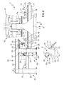
- machining centre 1 for machining components 2 made of wood for frames having an elongated shape.
- the machining centre 1 comprises a forming machine 3 in turn comprising a gantry frame 4 with two upright members 5 parallel to one another and to a substantially vertical direction 6 and a cross member 7, which is fixed to the free ends of the upright members 5, extends in a substantially horizontal direction 8 transversal to the direction 6, and is limited laterally in a horizontal direction 9 orthogonal to the directions 6 and 8 by two substantially flat faces 7a, 7b, on each of which is mounted a relative working head 10.
- the head 10 is connected in a conventional manner to the cross member 7 so as to perform, along the cross member 7 and driven by a conventional drive device that is not illustrated, rectilinear movements in the direction 8, and is provided with at least one electric spindle and a drilling unit (known and not illustrated) which are mounted in a conventional manner on the head 10 so as to perform, with respect to the head 10 and driven by a conventional drive device that is not illustrated, rectilinear movements in the direction 6.
- the working heads 10 can be moved in the direction 8 either independently of one another, or synchronously with one another.
- the forming machine 3 also comprises two longitudinal guiding members 11, which extend in the direction 9, are mounted inside the upright members 5, and support two gripping and transfer devices 12, 13 that face one another.
- Each device 12, 13 comprises a supporting bar 14, which is slidingly coupled to the longitudinal members 11 so as to perform, along the longitudinal members 11 and driven by a conventional drive device that is not illustrated, rectilinear movements in the direction 9, and is upperly limited by a substantially flat and horizontal surface to which a plurality of lower jaws 15 of relative clamping vices 16 are attached, which face the vices 16 of the other device 12, 13 and also comprise respective upper jaws 17 that are substantially L-shaped.
- the jaws 17 of each device 12, 13 are divided into a plurality of mutually independent sets of jaws 17 (in the specific case two sets of jaws 17), and the jaws 17 of each set of jaws 17 protrude upwards from a relative slide 18 connected in a conventional manner to the bar 14 so as to perform, with respect to the bar 14 and driven by a plurality of actuating cylinders 19 (in the specific case three actuating cylinders 19) connected to the bar 14, rectilinear movements in the direction 6 and move the relative jaws 17 between a locked position and a released position of at least one component 2.
- each component 2 is loaded, by hand or automatically, onto the gripping and transfer device 12 and is longitudinally profiled along a face 2a thereof protruding outwards from the vices 16 of the device 12 by the working head 10 mounted on the side 7a of the cross member 7.
- the component 2 is transferred from the vices 16 of the device 12 to the vices 16 of the device 13, and is then longitudinally profiled along a face 2b thereof opposite the face 2a and protruding outwards from the vices 16 of the device 13 by the working head 10 mounted on the side 7b of the cross member 7.
- the components 2 are removed from the device 13 by means of a sampling unit 20, which is aligned with the forming machine 3 in the direction 9, and is provided with a supporting frame 21 comprising two pairs of vertical rods 22 parallel to one another and to the direction 6.
- Each pair of vertical rods 22 supports a longitudinal guiding member 23 connected to the free ends of the relative vertical rods 22 parallel to the direction 9.
- the unit 20 also comprises a cross element 24, which extends between the longitudinal members 23 in the direction 8, is connected in a conventional manner to the longitudinal members 23 so as to perform, along the longitudinal members 23 and driven by a conventional drive device that is not illustrated, rectilinear movements in the direction 9, and supports a grip and transfer device D comprising a plurality of gripping and transferring members 25, in the specific case two gripping and transferring members 25, mounted on a side of the cross element 24.
- Each member 25 comprises a slide 26, which is connected in a conventional manner to the cross element 24 so as to perform, along the cross element 24 and driven by a conventional drive device that is not illustrated, rectilinear movements in the direction 8, and supports a clamping vice 27 comprising a lower jaw 28 connected in a conventional manner to the slide 26 so as to perform, with respect to said slide 26, rectilinear movements in the direction 6 and an upper jaw 29 connected in a conventional manner to the jaw 28 so as to perform, with respect to said jaw 28, rectilinear movements in the direction 6 between a locked position and a released position of at least one component 2.
- the machining centre 1 also comprises, in the specific case, two conventional inserting units 30 arranged on opposite sides of the frame 21 in the direction 8 for inserting coupling pins (not illustrated) inside relative holes 31 made by the heads 10 in the head ends of the components 2 parallel to the direction 8.
- Each unit 30 comprises a gumming nozzle 32, which is connected to a glue containing tank 33 by means of a pumping device 34, and is suitable to deliver glue inside the relative holes 31, and an insertion device 35, which is connected to a hopper 36 that contains pins, and is suitable to insert a pin (not illustrated) inside each relative hole 31.
- the machining centre 1 comprises a conveyor device 37, which extends in the direction 8, and in turn comprises a roller conveyor 38 suitable to receive the components 2 from the sampling unit 20 and a conveyor belt 39 arranged in series with the conveyor 38.
- the jaws 28, 29 of the vices 27 present a width, measured parallel to the direction 8, that is approximating by defect the distance between the jaws 15, 17 of two adjacent vices 16, and also the distance between two adjacent rollers of the conveyor 38.
- the jaws 28, 29 of the vices 27 are engaged between the jaws 15, 17 of the vices 16 of the device 13 enabling the unit 20 to remove the component 2 from the forming machine 3, feed it in sequence to the two units 30, and unload it onto the conveyor 38.
Landscapes
- Engineering & Computer Science (AREA)
- Mechanical Engineering (AREA)
- Life Sciences & Earth Sciences (AREA)
- Wood Science & Technology (AREA)
- Forests & Forestry (AREA)
- Milling, Drilling, And Turning Of Wood (AREA)
- Turning (AREA)
- Specific Conveyance Elements (AREA)
Claims (11)
- Centre d'usinage pour l'usinage de composants de forme allongée (2) composés de bois ou similaire, en particulier de composants (2) pour cadres, le centre d'usinage comprenant une machine à former (3) et au moins une unité d'échantillonnage (20) des éléments (2) provenant de la machine à former (3) ; la machine à former (3) comprenant, à son tour, une structure de portique (4) dotée de deux éléments droits (5) parallèles l'un à l'autre et à une première direction (6) sensiblement verticale et d'un élément transversal (7), qui est fixé aux extrémités libres des éléments droits (5), et s'étend dans une deuxième direction sensiblement horizontale (8) transversale à la première direction (6) ; un premier dispositif de préhension (12) doté d'au moins un premier étau de serrage (16) pour bloquer au moins un composant (2) parallèlement à la deuxième direction (8), un second dispositif de préhension (13) faisant face au premier dispositif de préhension (12) et doté d'au moins un deuxième étau de serrage (16) pour bloquer au moins un composant (2) parallèlement à la deuxième direction (8) ; et au moins une tête de travail (10) mobile le long de l'élément transversal (7) dans la deuxième direction (8) pour le profilage longitudinal des composants (2) bloqués dans les premier et/ou second dispositifs de préhension (12, 13) ; l'unité d'échantillonnage (20) comprenant au moins un dispositif de prise et de transfert (D) doté d'au moins un troisième étau de serrage (27) mobile dans une troisième direction (9) sensiblement orthogonale auxdites première et deuxième directions (6, 8) pour extraire au moins un composant (2) desdits premier et/ou second dispositifs de préhension (12, 13).
- Centre d'usinage selon la revendication 1, dans lequel le troisième étau de serrage (27) est en outre mobile dans la première direction (6) et/ou dans la deuxième direction (8).
- Centre d'usinage selon la revendication 1 ou 2, dans lequel l'unité d'échantillonnage (20) comprend un élément transversal (24), qui s'étend dans la deuxième direction (8) et est mobile dans la troisième direction (9) ; le dispositif de prise et de transfert (D) étant supporté par l'élément transversal (24).
- Centre d'usinage selon la revendication 3 et comprenant en outre au moins deux dispositifs de prise et de transfert (D) montés sur les côtés opposés dudit élément transversal (24).
- Centre d'usinage selon l'une quelconque des revendications précédentes, dans lequel chacun desdits premier et second dispositifs de préhension (12, 13) comprend une pluralité de premiers et, respectivement, deuxièmes étaux de serrage (16) ; le troisième étau de serrage (27) étant formé pour être inséré entre lesdits premiers ou deuxièmes étaux de serrage (16) adjacents l'un à l'autre dans ladite première direction (6) et/ou ladite troisième direction (9).
- Centre d'usinage selon l'une quelconque des revendications précédentes et comprenant en outre un transporteur (37) définissant un plan de support apte à collecter les composants (2) provenant de l'unité d'échantillonnage (20).
- Centre d'usinage selon l'une quelconque des revendications précédentes, dans lequel la tête de travail (10) comprend au moins un outil de forage pour forer le composant (2) dans ladite deuxième direction (8) ; le centre d'usinage comprenant en outre au moins une première unité d'insertion (30) pour insérer au moins une tige d'accouplement dans l'élément (2) maintenu à l'intérieur du troisième étau de serrage (27).
- Centre d'usinage selon l'une quelconque des revendications précédentes, dans lequel la tête de travail (10) comprend au moins un outil de fraisage pour former au moins un support dans l'élément (2) ; le centre d'usinage comprenant en outre au moins une seconde unité d'insertion (30) pour insérer au moins un élément de quincaillerie pour cadres à l'intérieur dudit support alors que le composant (2) est maintenu à l'intérieur du troisième étau de serrage (27).
- Centre d'usinage selon l'une quelconque des revendications précédentes et comprenant en outre un dispositif d'étiquetage et/ou de marquage du composant (2) maintenu à l'intérieur du troisième étau de serrage (27).
- Centre d'usinage selon l'une quelconque des revendications précédentes, dans lequel l'unité d'échantillonnage (20) comprend deux tiges verticales (22), un dispositif d'entraînement (23) monté sur les tiges verticales (22) parallèlement à la troisième direction (9), et un élément transversal horizontal (24) monté sur le dispositif d'entraînement (23) pour se déplacer dans la troisième direction (9) ; le troisième étau de serrage (27) étant mobile le long de l'élément transversal (24) dans la deuxième direction (8).
- Centre d'usinage selon l'une quelconque des revendications précédentes, dans lequel la machine à former comprend deux desdites têtes de travail (10) pour usiner en même temps deux composants (2) maintenus par les premier et second dispositifs de préhension (12, 13).
Applications Claiming Priority (1)
| Application Number | Priority Date | Filing Date | Title |
|---|---|---|---|
| ITBO2008A000535A IT1391400B1 (it) | 2008-09-02 | 2008-09-02 | Centro di lavoro per la lavorazione di componenti di legno o simili di forma allungata, in particolare componenti per infissi |
Publications (3)
| Publication Number | Publication Date |
|---|---|
| EP2159023A2 EP2159023A2 (fr) | 2010-03-03 |
| EP2159023A3 EP2159023A3 (fr) | 2010-10-13 |
| EP2159023B1 true EP2159023B1 (fr) | 2015-07-15 |
Family
ID=40672194
Family Applications (1)
| Application Number | Title | Priority Date | Filing Date |
|---|---|---|---|
| EP09169191.5A Active EP2159023B1 (fr) | 2008-09-02 | 2009-09-01 | Centre d'usinage pour usiner des composants fabriqués en bois ou similaire dotés d'une forme allongée, en particulier des composants pour cadres |
Country Status (2)
| Country | Link |
|---|---|
| EP (1) | EP2159023B1 (fr) |
| IT (1) | IT1391400B1 (fr) |
Families Citing this family (7)
| Publication number | Priority date | Publication date | Assignee | Title |
|---|---|---|---|---|
| JP5783695B2 (ja) * | 2010-08-23 | 2015-09-24 | 株式会社トーア | 木材用認識タグの取付け方法 |
| IT1402782B1 (it) * | 2010-10-21 | 2013-09-18 | Working Process S R L | Centro di lavoro con piano di riscontro e raddrizzamento separato |
| ITPC20110018A1 (it) * | 2011-08-05 | 2013-02-06 | Cml S R L | Centro di lavoro per la lavorazione del legno |
| CN109926491B (zh) * | 2019-03-12 | 2024-08-16 | 中山吉田工业有限公司 | 移管活塞冲孔加工设备 |
| US11520320B2 (en) * | 2019-03-20 | 2022-12-06 | Michael Weinig, Inc | System for optimizing the organization of components for the manufacture of wood products |
| DE102020002322B4 (de) * | 2020-04-09 | 2022-06-09 | Michael Weinig Aktiengesellschaft | Anlage zur Bearbeitung von Werkstücken aus Holz, Kunststoff, Aluminium und dergleichen sowie Verfahren zur Übergabe von Werkstücken zwischen einer ersten und einer zweiten Spanneinrichtung |
| IT202000030278A1 (it) * | 2020-12-10 | 2022-06-10 | Scm Group Spa | Macchina utensile. |
Family Cites Families (4)
| Publication number | Priority date | Publication date | Assignee | Title |
|---|---|---|---|---|
| DE19846819A1 (de) * | 1998-10-10 | 2000-04-13 | Biesse Spa | Plattenbearbeitungsmaschine |
| US6688352B2 (en) * | 2001-04-06 | 2004-02-10 | Uniteam S.P.A. | Multi-axis work center, for multiple production, in particular for wood working |
| ITMO20060022A1 (it) * | 2006-01-20 | 2007-07-21 | Scm Group Spa | Macchina per la lavorazione di elementi di legno con carico e scarico automatico di detti elementi e metodo per caricare detti elementi |
| ITBO20070356A1 (it) * | 2007-05-14 | 2008-11-15 | Biesse Spa | Metodo per la lavorazione di componenti di legno o simili, in particolare componenti per infissi |
-
2008
- 2008-09-02 IT ITBO2008A000535A patent/IT1391400B1/it active
-
2009
- 2009-09-01 EP EP09169191.5A patent/EP2159023B1/fr active Active
Also Published As
| Publication number | Publication date |
|---|---|
| ITBO20080535A1 (it) | 2010-03-03 |
| EP2159023A3 (fr) | 2010-10-13 |
| IT1391400B1 (it) | 2011-12-23 |
| EP2159023A2 (fr) | 2010-03-03 |
Similar Documents
| Publication | Publication Date | Title |
|---|---|---|
| EP2159023B1 (fr) | Centre d'usinage pour usiner des composants fabriqués en bois ou similaire dotés d'une forme allongée, en particulier des composants pour cadres | |
| US10668643B2 (en) | Machining device | |
| EP2138247B1 (fr) | Installation de fabrication dotée d'une presse à plier | |
| EP2995453B1 (fr) | Dispositif de transport pour des objets usines dans une machine d'usinage | |
| WO2017049564A1 (fr) | Dispositif de transport cyclique à double pont | |
| CN108025451A (zh) | 加工设备 | |
| TWI476130B (zh) | 打標裝置 | |
| ITBO20120241A1 (it) | Metodo e macchina per la lavorazione di componenti di legno o simili | |
| EP2415571B1 (fr) | Machine pour l'usinage de cadres en bois ou analogues | |
| EP3110683A1 (fr) | Dispositif et procédé de changement de cadres de serrage portant des pièces de carrosserie entre un dispositif de transport de cadres de serrage et un convoyeur de cadres par l'intermédiaire de magasins à cadres de serrage | |
| EP1832402B1 (fr) | Moulurière pour mettre en forme longitudinalement des pièces de forme allongée en bois ou similaire, en particulier des parties de cadres de portes et fenêtres | |
| DE102020001963B4 (de) | Fertigungszelle mit Werkstückrückführung und Betriebsverfahren hierzu | |
| ES2361706T3 (es) | Método y máquina para mecanizar componentes de madera o similares. | |
| EP2105269B1 (fr) | Procédé et machine pour profiler des composants en bois allongé ou similaire, spécialement des composants pour les cadres de porte et de fenêtre | |
| EP2508314B1 (fr) | Appareil et procédé d'usinage de panneaux | |
| CN109514252B (zh) | 一种穿刺针组装机的治具条循环机构 | |
| DE102007028786B4 (de) | Vorrichtung zum Fördern von Holzplatten oder dergleichen | |
| ITUB20155112A1 (it) | Macchina per la lavorazione di barre di alluminio, leghe leggere, pvc o simili | |
| DE4027900A1 (de) | Stanz-biegemaschine | |
| SE520106C2 (sv) | Matningsanordning | |
| EP2159021B1 (fr) | Méthode et machines de traitement des composants en bois | |
| DE102014218310B4 (de) | Transportvorrichtung für in einer Bearbeitungsmaschine zu bearbeitende und dort bearbeitete Objekte | |
| DE102014218308B4 (de) | Transportvorrichtung für in einer Bearbeitungsmaschine zu bearbeitende und/oder dort bearbeitete Objekte | |
| EP2022611B1 (fr) | Machine pour travailler des pièces en bois ou similaire, en particulier des pièces de portes et de fenêtres | |
| EP1475204A1 (fr) | Machine-outil servant a l'usinage de panneaux de bois ou similaires |
Legal Events
| Date | Code | Title | Description |
|---|---|---|---|
| PUAI | Public reference made under article 153(3) epc to a published international application that has entered the european phase |
Free format text: ORIGINAL CODE: 0009012 |
|
| AK | Designated contracting states |
Kind code of ref document: A2 Designated state(s): AT BE BG CH CY CZ DE DK EE ES FI FR GB GR HR HU IE IS IT LI LT LU LV MC MK MT NL NO PL PT RO SE SI SK SM TR |
|
| AX | Request for extension of the european patent |
Extension state: AL BA RS |
|
| PUAL | Search report despatched |
Free format text: ORIGINAL CODE: 0009013 |
|
| AK | Designated contracting states |
Kind code of ref document: A3 Designated state(s): AT BE BG CH CY CZ DE DK EE ES FI FR GB GR HR HU IE IS IT LI LT LU LV MC MK MT NL NO PL PT RO SE SI SK SM TR |
|
| AX | Request for extension of the european patent |
Extension state: AL BA RS |
|
| 17P | Request for examination filed |
Effective date: 20110413 |
|
| GRAP | Despatch of communication of intention to grant a patent |
Free format text: ORIGINAL CODE: EPIDOSNIGR1 |
|
| RIC1 | Information provided on ipc code assigned before grant |
Ipc: B23Q 7/00 20060101ALI20150112BHEP Ipc: B23Q 7/04 20060101ALI20150112BHEP Ipc: B27M 1/08 20060101AFI20150112BHEP |
|
| INTG | Intention to grant announced |
Effective date: 20150129 |
|
| GRAS | Grant fee paid |
Free format text: ORIGINAL CODE: EPIDOSNIGR3 |
|
| GRAA | (expected) grant |
Free format text: ORIGINAL CODE: 0009210 |
|
| AK | Designated contracting states |
Kind code of ref document: B1 Designated state(s): AT BE BG CH CY CZ DE DK EE ES FI FR GB GR HR HU IE IS IT LI LT LU LV MC MK MT NL NO PL PT RO SE SI SK SM TR |
|
| REG | Reference to a national code |
Ref country code: CH Ref legal event code: EP Ref country code: GB Ref legal event code: FG4D |
|
| REG | Reference to a national code |
Ref country code: IE Ref legal event code: FG4D |
|
| REG | Reference to a national code |
Ref country code: AT Ref legal event code: REF Ref document number: 736548 Country of ref document: AT Kind code of ref document: T Effective date: 20150815 |
|
| REG | Reference to a national code |
Ref country code: DE Ref legal event code: R096 Ref document number: 602009032208 Country of ref document: DE |
|
| REG | Reference to a national code |
Ref country code: AT Ref legal event code: MK05 Ref document number: 736548 Country of ref document: AT Kind code of ref document: T Effective date: 20150715 |
|
| REG | Reference to a national code |
Ref country code: NL Ref legal event code: MP Effective date: 20150715 |
|
| REG | Reference to a national code |
Ref country code: LT Ref legal event code: MG4D |
|
| PG25 | Lapsed in a contracting state [announced via postgrant information from national office to epo] |
Ref country code: LT Free format text: LAPSE BECAUSE OF FAILURE TO SUBMIT A TRANSLATION OF THE DESCRIPTION OR TO PAY THE FEE WITHIN THE PRESCRIBED TIME-LIMIT Effective date: 20150715 Ref country code: GR Free format text: LAPSE BECAUSE OF FAILURE TO SUBMIT A TRANSLATION OF THE DESCRIPTION OR TO PAY THE FEE WITHIN THE PRESCRIBED TIME-LIMIT Effective date: 20151016 Ref country code: LV Free format text: LAPSE BECAUSE OF FAILURE TO SUBMIT A TRANSLATION OF THE DESCRIPTION OR TO PAY THE FEE WITHIN THE PRESCRIBED TIME-LIMIT Effective date: 20150715 Ref country code: NO Free format text: LAPSE BECAUSE OF FAILURE TO SUBMIT A TRANSLATION OF THE DESCRIPTION OR TO PAY THE FEE WITHIN THE PRESCRIBED TIME-LIMIT Effective date: 20151015 Ref country code: FI Free format text: LAPSE BECAUSE OF FAILURE TO SUBMIT A TRANSLATION OF THE DESCRIPTION OR TO PAY THE FEE WITHIN THE PRESCRIBED TIME-LIMIT Effective date: 20150715 |
|
| PG25 | Lapsed in a contracting state [announced via postgrant information from national office to epo] |
Ref country code: HR Free format text: LAPSE BECAUSE OF FAILURE TO SUBMIT A TRANSLATION OF THE DESCRIPTION OR TO PAY THE FEE WITHIN THE PRESCRIBED TIME-LIMIT Effective date: 20150715 Ref country code: SE Free format text: LAPSE BECAUSE OF FAILURE TO SUBMIT A TRANSLATION OF THE DESCRIPTION OR TO PAY THE FEE WITHIN THE PRESCRIBED TIME-LIMIT Effective date: 20150715 Ref country code: PL Free format text: LAPSE BECAUSE OF FAILURE TO SUBMIT A TRANSLATION OF THE DESCRIPTION OR TO PAY THE FEE WITHIN THE PRESCRIBED TIME-LIMIT Effective date: 20150715 Ref country code: PT Free format text: LAPSE BECAUSE OF FAILURE TO SUBMIT A TRANSLATION OF THE DESCRIPTION OR TO PAY THE FEE WITHIN THE PRESCRIBED TIME-LIMIT Effective date: 20151116 Ref country code: ES Free format text: LAPSE BECAUSE OF FAILURE TO SUBMIT A TRANSLATION OF THE DESCRIPTION OR TO PAY THE FEE WITHIN THE PRESCRIBED TIME-LIMIT Effective date: 20150715 Ref country code: AT Free format text: LAPSE BECAUSE OF FAILURE TO SUBMIT A TRANSLATION OF THE DESCRIPTION OR TO PAY THE FEE WITHIN THE PRESCRIBED TIME-LIMIT Effective date: 20150715 |
|
| REG | Reference to a national code |
Ref country code: DE Ref legal event code: R097 Ref document number: 602009032208 Country of ref document: DE |
|
| PG25 | Lapsed in a contracting state [announced via postgrant information from national office to epo] |
Ref country code: MC Free format text: LAPSE BECAUSE OF FAILURE TO SUBMIT A TRANSLATION OF THE DESCRIPTION OR TO PAY THE FEE WITHIN THE PRESCRIBED TIME-LIMIT Effective date: 20150715 Ref country code: SK Free format text: LAPSE BECAUSE OF FAILURE TO SUBMIT A TRANSLATION OF THE DESCRIPTION OR TO PAY THE FEE WITHIN THE PRESCRIBED TIME-LIMIT Effective date: 20150715 Ref country code: IT Free format text: LAPSE BECAUSE OF FAILURE TO SUBMIT A TRANSLATION OF THE DESCRIPTION OR TO PAY THE FEE WITHIN THE PRESCRIBED TIME-LIMIT Effective date: 20150715 Ref country code: LU Free format text: LAPSE BECAUSE OF FAILURE TO SUBMIT A TRANSLATION OF THE DESCRIPTION OR TO PAY THE FEE WITHIN THE PRESCRIBED TIME-LIMIT Effective date: 20150901 Ref country code: EE Free format text: LAPSE BECAUSE OF FAILURE TO SUBMIT A TRANSLATION OF THE DESCRIPTION OR TO PAY THE FEE WITHIN THE PRESCRIBED TIME-LIMIT Effective date: 20150715 Ref country code: CZ Free format text: LAPSE BECAUSE OF FAILURE TO SUBMIT A TRANSLATION OF THE DESCRIPTION OR TO PAY THE FEE WITHIN THE PRESCRIBED TIME-LIMIT Effective date: 20150715 Ref country code: DK Free format text: LAPSE BECAUSE OF FAILURE TO SUBMIT A TRANSLATION OF THE DESCRIPTION OR TO PAY THE FEE WITHIN THE PRESCRIBED TIME-LIMIT Effective date: 20150715 |
|
| REG | Reference to a national code |
Ref country code: CH Ref legal event code: PL |
|
| PLBE | No opposition filed within time limit |
Free format text: ORIGINAL CODE: 0009261 |
|
| STAA | Information on the status of an ep patent application or granted ep patent |
Free format text: STATUS: NO OPPOSITION FILED WITHIN TIME LIMIT |
|
| PG25 | Lapsed in a contracting state [announced via postgrant information from national office to epo] |
Ref country code: RO Free format text: LAPSE BECAUSE OF FAILURE TO SUBMIT A TRANSLATION OF THE DESCRIPTION OR TO PAY THE FEE WITHIN THE PRESCRIBED TIME-LIMIT Effective date: 20150715 |
|
| 26N | No opposition filed |
Effective date: 20160418 |
|
| GBPC | Gb: european patent ceased through non-payment of renewal fee |
Effective date: 20151015 |
|
| REG | Reference to a national code |
Ref country code: IE Ref legal event code: MM4A |
|
| PG25 | Lapsed in a contracting state [announced via postgrant information from national office to epo] |
Ref country code: IS Free format text: LAPSE BECAUSE OF FAILURE TO SUBMIT A TRANSLATION OF THE DESCRIPTION OR TO PAY THE FEE WITHIN THE PRESCRIBED TIME-LIMIT Effective date: 20150715 |
|
| REG | Reference to a national code |
Ref country code: FR Ref legal event code: ST Effective date: 20160531 |
|
| PG25 | Lapsed in a contracting state [announced via postgrant information from national office to epo] |
Ref country code: IE Free format text: LAPSE BECAUSE OF NON-PAYMENT OF DUE FEES Effective date: 20150901 Ref country code: GB Free format text: LAPSE BECAUSE OF NON-PAYMENT OF DUE FEES Effective date: 20151015 Ref country code: CH Free format text: LAPSE BECAUSE OF NON-PAYMENT OF DUE FEES Effective date: 20150930 Ref country code: LI Free format text: LAPSE BECAUSE OF NON-PAYMENT OF DUE FEES Effective date: 20150930 |
|
| PG25 | Lapsed in a contracting state [announced via postgrant information from national office to epo] |
Ref country code: FR Free format text: LAPSE BECAUSE OF NON-PAYMENT OF DUE FEES Effective date: 20150930 Ref country code: SI Free format text: LAPSE BECAUSE OF FAILURE TO SUBMIT A TRANSLATION OF THE DESCRIPTION OR TO PAY THE FEE WITHIN THE PRESCRIBED TIME-LIMIT Effective date: 20150715 |
|
| PG25 | Lapsed in a contracting state [announced via postgrant information from national office to epo] |
Ref country code: BE Free format text: LAPSE BECAUSE OF FAILURE TO SUBMIT A TRANSLATION OF THE DESCRIPTION OR TO PAY THE FEE WITHIN THE PRESCRIBED TIME-LIMIT Effective date: 20150715 |
|
| PG25 | Lapsed in a contracting state [announced via postgrant information from national office to epo] |
Ref country code: MT Free format text: LAPSE BECAUSE OF FAILURE TO SUBMIT A TRANSLATION OF THE DESCRIPTION OR TO PAY THE FEE WITHIN THE PRESCRIBED TIME-LIMIT Effective date: 20150715 |
|
| PG25 | Lapsed in a contracting state [announced via postgrant information from national office to epo] |
Ref country code: HU Free format text: LAPSE BECAUSE OF FAILURE TO SUBMIT A TRANSLATION OF THE DESCRIPTION OR TO PAY THE FEE WITHIN THE PRESCRIBED TIME-LIMIT; INVALID AB INITIO Effective date: 20090901 Ref country code: SM Free format text: LAPSE BECAUSE OF FAILURE TO SUBMIT A TRANSLATION OF THE DESCRIPTION OR TO PAY THE FEE WITHIN THE PRESCRIBED TIME-LIMIT Effective date: 20150715 Ref country code: BG Free format text: LAPSE BECAUSE OF FAILURE TO SUBMIT A TRANSLATION OF THE DESCRIPTION OR TO PAY THE FEE WITHIN THE PRESCRIBED TIME-LIMIT Effective date: 20150715 |
|
| PG25 | Lapsed in a contracting state [announced via postgrant information from national office to epo] |
Ref country code: CY Free format text: LAPSE BECAUSE OF FAILURE TO SUBMIT A TRANSLATION OF THE DESCRIPTION OR TO PAY THE FEE WITHIN THE PRESCRIBED TIME-LIMIT Effective date: 20150715 Ref country code: NL Free format text: LAPSE BECAUSE OF FAILURE TO SUBMIT A TRANSLATION OF THE DESCRIPTION OR TO PAY THE FEE WITHIN THE PRESCRIBED TIME-LIMIT Effective date: 20150715 |
|
| PG25 | Lapsed in a contracting state [announced via postgrant information from national office to epo] |
Ref country code: TR Free format text: LAPSE BECAUSE OF FAILURE TO SUBMIT A TRANSLATION OF THE DESCRIPTION OR TO PAY THE FEE WITHIN THE PRESCRIBED TIME-LIMIT Effective date: 20150715 |
|
| PG25 | Lapsed in a contracting state [announced via postgrant information from national office to epo] |
Ref country code: MK Free format text: LAPSE BECAUSE OF FAILURE TO SUBMIT A TRANSLATION OF THE DESCRIPTION OR TO PAY THE FEE WITHIN THE PRESCRIBED TIME-LIMIT Effective date: 20150715 |
|
| PGFP | Annual fee paid to national office [announced via postgrant information from national office to epo] |
Ref country code: DE Payment date: 20250926 Year of fee payment: 17 |