EP2159165A1 - Appareil pour le conditionnement thermique d'un produit - Google Patents
Appareil pour le conditionnement thermique d'un produit Download PDFInfo
- Publication number
- EP2159165A1 EP2159165A1 EP09167931A EP09167931A EP2159165A1 EP 2159165 A1 EP2159165 A1 EP 2159165A1 EP 09167931 A EP09167931 A EP 09167931A EP 09167931 A EP09167931 A EP 09167931A EP 2159165 A1 EP2159165 A1 EP 2159165A1
- Authority
- EP
- European Patent Office
- Prior art keywords
- reaction vessel
- compartment
- component
- product
- membrane
- Prior art date
- Legal status (The legal status is an assumption and is not a legal conclusion. Google has not performed a legal analysis and makes no representation as to the accuracy of the status listed.)
- Withdrawn
Links
- 230000003750 conditioning effect Effects 0.000 title description 7
- 238000006243 chemical reaction Methods 0.000 claims abstract description 135
- 239000012528 membrane Substances 0.000 claims abstract description 34
- 230000000149 penetrating effect Effects 0.000 claims description 30
- 238000004891 communication Methods 0.000 claims description 8
- 239000012530 fluid Substances 0.000 claims description 8
- 235000013305 food Nutrition 0.000 abstract description 24
- XLYOFNOQVPJJNP-UHFFFAOYSA-N water Substances O XLYOFNOQVPJJNP-UHFFFAOYSA-N 0.000 abstract description 13
- 235000008733 Citrus aurantifolia Nutrition 0.000 abstract description 8
- 235000011941 Tilia x europaea Nutrition 0.000 abstract description 8
- 239000004571 lime Substances 0.000 abstract description 8
- 238000004806 packaging method and process Methods 0.000 abstract description 3
- 238000007669 thermal treatment Methods 0.000 abstract 1
- 239000000047 product Substances 0.000 description 59
- 239000000376 reactant Substances 0.000 description 19
- 238000010438 heat treatment Methods 0.000 description 16
- ODINCKMPIJJUCX-UHFFFAOYSA-N calcium oxide Inorganic materials [Ca]=O ODINCKMPIJJUCX-UHFFFAOYSA-N 0.000 description 11
- 239000000292 calcium oxide Substances 0.000 description 7
- 239000004743 Polypropylene Substances 0.000 description 6
- 238000001816 cooling Methods 0.000 description 6
- 229910052751 metal Inorganic materials 0.000 description 6
- 239000002184 metal Substances 0.000 description 6
- 238000000034 method Methods 0.000 description 6
- -1 polypropylene Polymers 0.000 description 6
- 229920001155 polypropylene Polymers 0.000 description 6
- 239000000126 substance Substances 0.000 description 6
- 239000000463 material Substances 0.000 description 5
- 239000000203 mixture Substances 0.000 description 5
- BRPQOXSCLDDYGP-UHFFFAOYSA-N calcium oxide Chemical compound [O-2].[Ca+2] BRPQOXSCLDDYGP-UHFFFAOYSA-N 0.000 description 4
- 235000012255 calcium oxide Nutrition 0.000 description 4
- 230000001954 sterilising effect Effects 0.000 description 4
- 239000000853 adhesive Substances 0.000 description 3
- 230000001070 adhesive effect Effects 0.000 description 3
- 239000004411 aluminium Substances 0.000 description 3
- 229910052782 aluminium Inorganic materials 0.000 description 3
- XAGFODPZIPBFFR-UHFFFAOYSA-N aluminium Chemical compound [Al] XAGFODPZIPBFFR-UHFFFAOYSA-N 0.000 description 3
- 238000007789 sealing Methods 0.000 description 3
- 239000007787 solid Substances 0.000 description 3
- UXVMQQNJUSDDNG-UHFFFAOYSA-L Calcium chloride Chemical compound [Cl-].[Cl-].[Ca+2] UXVMQQNJUSDDNG-UHFFFAOYSA-L 0.000 description 2
- 230000004913 activation Effects 0.000 description 2
- 239000001110 calcium chloride Substances 0.000 description 2
- 229910001628 calcium chloride Inorganic materials 0.000 description 2
- 238000012986 modification Methods 0.000 description 2
- 230000004048 modification Effects 0.000 description 2
- 238000011012 sanitization Methods 0.000 description 2
- 235000014347 soups Nutrition 0.000 description 2
- 238000012546 transfer Methods 0.000 description 2
- 229920000219 Ethylene vinyl alcohol Polymers 0.000 description 1
- CBENFWSGALASAD-UHFFFAOYSA-N Ozone Chemical compound [O-][O+]=O CBENFWSGALASAD-UHFFFAOYSA-N 0.000 description 1
- 239000004698 Polyethylene Substances 0.000 description 1
- 241001122767 Theaceae Species 0.000 description 1
- ATJFFYVFTNAWJD-UHFFFAOYSA-N Tin Chemical compound [Sn] ATJFFYVFTNAWJD-UHFFFAOYSA-N 0.000 description 1
- 235000014171 carbonated beverage Nutrition 0.000 description 1
- 239000007795 chemical reaction product Substances 0.000 description 1
- 235000016213 coffee Nutrition 0.000 description 1
- 235000013353 coffee beverage Nutrition 0.000 description 1
- 150000001875 compounds Chemical class 0.000 description 1
- 230000001143 conditioned effect Effects 0.000 description 1
- 239000002537 cosmetic Substances 0.000 description 1
- 230000000694 effects Effects 0.000 description 1
- UFRKOOWSQGXVKV-UHFFFAOYSA-N ethene;ethenol Chemical compound C=C.OC=C UFRKOOWSQGXVKV-UHFFFAOYSA-N 0.000 description 1
- 239000004715 ethylene vinyl alcohol Substances 0.000 description 1
- 230000002349 favourable effect Effects 0.000 description 1
- 235000013350 formula milk Nutrition 0.000 description 1
- 235000020278 hot chocolate Nutrition 0.000 description 1
- 238000010348 incorporation Methods 0.000 description 1
- 238000002347 injection Methods 0.000 description 1
- 239000007924 injection Substances 0.000 description 1
- 239000007788 liquid Substances 0.000 description 1
- 235000021056 liquid food Nutrition 0.000 description 1
- 230000013011 mating Effects 0.000 description 1
- 239000004033 plastic Substances 0.000 description 1
- 229920003023 plastic Polymers 0.000 description 1
- 229920000573 polyethylene Polymers 0.000 description 1
- 238000005096 rolling process Methods 0.000 description 1
- 229910001220 stainless steel Inorganic materials 0.000 description 1
- 239000010935 stainless steel Substances 0.000 description 1
- 238000003856 thermoforming Methods 0.000 description 1
- 229910052718 tin Inorganic materials 0.000 description 1
- 239000011135 tin Substances 0.000 description 1
Images


Classifications
-
- B—PERFORMING OPERATIONS; TRANSPORTING
- B65—CONVEYING; PACKING; STORING; HANDLING THIN OR FILAMENTARY MATERIAL
- B65D—CONTAINERS FOR STORAGE OR TRANSPORT OF ARTICLES OR MATERIALS, e.g. BAGS, BARRELS, BOTTLES, BOXES, CANS, CARTONS, CRATES, DRUMS, JARS, TANKS, HOPPERS, FORWARDING CONTAINERS; ACCESSORIES, CLOSURES, OR FITTINGS THEREFOR; PACKAGING ELEMENTS; PACKAGES
- B65D81/00—Containers, packaging elements, or packages, for contents presenting particular transport or storage problems, or adapted to be used for non-packaging purposes after removal of contents
- B65D81/34—Containers, packaging elements, or packages, for contents presenting particular transport or storage problems, or adapted to be used for non-packaging purposes after removal of contents for packaging foodstuffs or other articles intended to be cooked or heated within the package
- B65D81/3484—Packages having self-contained heating means, e.g. heating generated by the reaction of two chemicals
Definitions
- the present invention generally relates to a self-contained food packaging system, and more particularly an apparatus for heating or cooling, or a container for packaging food including such an apparatus.
- Such an apparatus should be easy to sterilize and incorporate into a food package, should be able to be packaged with pressurized food, and should be safe to handle.
- the present invention overcomes the disadvantages of prior art by providing a self-contained reaction vessel that, depending on the chemical reactants contained therein, heat or cool a food product in contact with the vessel.
- a reaction vessel in one embodiment, includes a sealed container having a reactant and a perforator, where the perforator can be moved by manipulating the reaction vessel to puncture the sealed container.
- a container and a reaction vessel is provided, where the reaction vessel is situated substantially within the food, where the reaction vessel includes a sealed container having a reactant, and a perforator or actuator that can pierce the sealed container.
- a container and a reaction vessel is provided, where the reaction vessel is sealed and is situated substantially within the food, where the reaction vessel generates heat by mixing reactants including water and lime.
- a reaction vessel for a container is provided that is hermetically sealed against overpressure and underpressure.
- a container having a reaction vessel for thermally treating food within the container that permits food to be store using aseptic or hermetically treated methods.
- the container may be used to store, for example and without limitation, coffee, hot chocolate, soups with or without morsels.
- a reaction vessel for thermally treating food is provided that is a self-contained vessel that can be later provided to food packers for incorporation into a container and provided with food.
- the invention proposes an independent reaction vessel intended to be implemented inside a container to thermally condition, heating or cooling, a product to facilitate the mixing and reaction of a first component and a second component, where said reaction vessel includes a flexible wall portion, said reaction vessel comprising:
- the penetrating part comprises a top planar portion and a top cylindrical portion and is linked to the base comprising a bottom cylindrical portion by a flange to which the membrane is attached for defining the both compartments.
- the penetrating part is of such wideness in comparison with the size of the inner walls of the outer body that the thickness of the product around the penetrating part is substantially the same all around the penetrating part.
- said reaction vessel comprises a metallic reaction vessel body constituting said penetrating part and said base, said metallic reaction vessel being further closed by a flexible reaction vessel bottom.
- the reaction bottom vessel is also realized in metal.
- said reaction vessel is configured to contain the first component, the second component, and any products of reaction of the first component and the second component.
- said member is a membrane, and where actuator includes one or more piercing elements disposed near said membrane.
- the invention also concerns an independent reaction vessel intended to be implemented inside a container to thermally condition a product to facilitate the mixing and reaction of a first component and a second component, where said reaction vessel is in thermal contact with a product, characterized in that said reaction vessel comprises:
- said actuator is not affixed to said reaction vessel. It is also possible to envisage, according to a specific characteristic that said actuator is affixed to said reaction vessel.
- said reaction vessel is configured to contain the first component, the second component, and any products of reaction of the first component and the second component.
- the reaction vessel includes a flexible portion that, when flexed, engages said actuator to pierce said membrane.
- said first component includes calcium oxide or calcium chloride and said second component includes water.
- the invention also concerns a container to thermally condition a product, said container comprising:
- reaction vessel an independent reaction vessel according the invention; a flexible portion adjacent to the flexible wall portion of the reaction vessel so that an inward movement of flexible portion will affect reaction vessel and activate thermal conditioning.
- the invention finally concerns a method of sterilizing a product and container, said method comprising:
- said sterilizing includes heating the container.
- Figure 1 is a perspective view of one embodiment of a container 100 for thermally conditioning, that is heating or cooling, a product.
- the product may be, for example and without limitation, an edible product such as a food, a soup, or a drink, such as a baby formula or tea.
- the product may also be product that is not edible, such a wax to be used as a hot wax in a cosmetic treatment.
- container 100 includes a removable lid 101 and an outer body 103.
- Outer body 103 is shown as being generally cylindrical, but may, in alternative embodiments, have the shape of a bowl, cup, or tub or other shape as is convenient for utilizing the thermally conditioned product, outer body 103 is transparent, translucent, or opaque, or includes printing or labels on all or part of its surface.
- Figure 2A is a sectional view and Figure 2B is a perspective sectional view of one embodiment of a container 100, which may be generally similar to the embodiment illustrated in FIG. 1 , except as further detailed below. Where possible, similar elements are identified with identical reference numerals in the depiction of the embodiments of FIGS. 1 and 2 .
- Container 100 includes a reaction vessel 210 comprising a reaction vessel body 211 and, reaction vessel bottom 213, and outer body 103 which includes a side 201 that extends from an opening 203 to a bottom 205.
- bottom 205 further includes a portion 207 that is adjacent to reaction vessel bottom 213.
- Reaction vessel 210 is interior to outer body 103 and forms a hermetic seal with the outer bottom at a location 209 which is near side 201 and/or bottom 205.
- the seal at location 209 can be formed in a number of ways including, but not limited to, a press fit, an adhesive or other joining technique, or thermoforming outer body 103 to a protruding feature on reaction vessel 210.
- Volume 202 includes the interior of outer body 103 including side 201 from opening 203 to sealing location 209, not including the volume occupied by reaction vessel 210.
- some or all of volume 202 includes a product P. Locating reaction vessel 210 wholly or substantially within outer body 103 is advantageous, as this allows for efficient heating or cooling of the product contained therein with a minimal amount of heat transfer between the reaction vessel and the container exterior.
- the reaction vessel 210 comprises a base 320 comprising a second compartment and enabling the reaction vessel to be affixed and sealed inside the outer body 103 and a penetrating part 310 in which is implemented a second compartment and having an outer shape less wide than the inner space of the outer body.
- the wideness of the penetrating part 310 enables the product to be introduced between the penetrating part and the inner walls of the outer body in order for the penetrating part to be substantially within the product.
- the penetrating part 310 is of such wideness in comparison with the wideness of the inner walls of the outer body that the thickness of the product around the penetrating part is substantially the same all around the penetrating part.
- reaction vessel body 211 is compatible with the edible product - that is, it will not contaminate or be corroded or dissolved by the edible product or any other material occupying volume 202. Further, it is preferred, but not required that outer surface 212 and/or the inner surface 204 can be sterilized for use with edible products packaged therein.
- Outer body 103 may be formed from a variety of materials selected for their ability to maintain shape, resist moisture or gas permeation, and ability to be sanitized for filling with a food product.
- Materials selection is well known in the art and may include, but is not limited to, an injection molded polypropylene, a thermoformed polypropylene, or a thermoformed polypropylene/EVOH/polypropylene.
- the material and thickness may be chosen for its ability to maintain shape and resist gas permeation.
- Methods of sanitizing, when required, include, but are not limited to, heating or treating with ozone or other chemicals.
- FIG. 3 is a detailed view of one embodiment of a reaction vessel 210, which may be generally similar to the embodiments illustrated in FIGS. 2A and 2B , except as further detailed below. Where possible, similar elements are identified with identical reference numerals in the depiction of the embodiments of FIGS. 1, 2A , 2B , and 3 .
- reaction vessel 210 provides thermal conditioning of a product within volume 202. It is preferred, though not necessary, that reaction vessel 210 be structurally secure to contain the reacts and products within the vessel.
- the independent reaction vessel 210 according to the invention contains the components to produce the necessary chemical reactions to create or absorb heat from product P.
- reaction vessel body 211 is a metal can formed from aluminium, tin, or stainless steel
- reaction vessel bottom 213 is a metal piece that is formed with to be flexible when joined to the reaction vessel body.
- varnished aluminium may be used to resist chemical activity with specific products.
- Reaction vessel body 211 and reaction vessel body 213 are thus, in one embodiment, metal pieces that are sealed along joint 303.
- Joint 303 may be a weld, crimped, or adhesive joint.
- the outer portion of reaction vessel 210 is preferably, thought not necessarily, formed from metal to ensures safe operation, by containing any reactants and reaction products within the reaction vessel, and efficient heat transfer with product P. Metal surfaces are also easily treated to be aseptic when required.
- reaction vessel 210 is formed of materials with sufficient strength to fully contain heated reactants and products, both during storage of the reactants and during and after reactions are completed.
- reaction vessel 210 is sufficiently strong to maintain its shape when packaged in a pressurized container, such as when product P is pressurized.
- reaction vessel body 211 and reaction vessel bottom 213 are formed from metal sheet having a thickness of approximately 0.2 mm to 0.8 mm.
- reaction vessel body 211 may be formed by stamping and reaction vessel bottom 213 is formed by stamping and rolling.
- Reaction vessel bottom 213 has a central portion 325 which may move axially towards first compartment 310. Central portion 325 is adjacent to portion 207 of outer body 103 so that an inward movement of portion 207 will affect the volume of reaction vessel 210. This motion may be used to activate thermal conditioning, as described subsequently.
- reaction vessel 210 may, for example and without limitation, include two or more reactants separated during storage.
- reaction vessel body 211 includes a top planar portion 311, a top cylindrical portion 313, a flange 321, and a bottom cylindrical portion 323.
- Reaction vessel 210 also includes a membrane 301 and a perforator or actuator 330.
- Membrane 301 is attached to flange 321, defining a first compartment 310, having a volume V1, that is bound by top planar portion 311, top cylindrical portion 313, and the membrane, and a second compartment 320, having a volume V2 that is bound by the membrane, bottom cylindrical portion 323 and reaction vessel bottom 213.
- membrane 301 is aluminium coated or laminated with polyethylene or polypropylene, and is jointed to flange 321 with an adhesive or by heat or cold seal.
- Figure 4 is a sectional view 2-2 showing detail of one embodiment of perforator 330
- Figure 5 is a top view of the perforator, which may be generally similar to the embodiments illustrated in FIGS. 2A , 2B , and 3 except as further detailed below. Where possible, similar elements are identified with identical reference numerals in the depiction of the embodiments of FIGS. 1, 2A , 2B , 3, 4 and 5 .
- Perforator 330 is contained within second compartment 320.
- perforator 330 formed from a plastic such as polypropylene and is loosely placed within second compartment 320.
- Perforator 330 is adapted to move axially along reaction vessel 210 and pierce membrane 310.
- Perforator 330 includes a base 401 having a plurality of holes 403, and has a central protrusion 405 on one side of the base and guide members 407 and piercing elements 409 on the other side of the base.
- guide members 407 include one or more portions that extend part or all the way around the circumference of perforator 330. The purpose of guide members 407 is to prevent perforator 330 from canting while moving towards membrane 301.
- piercing elements 409 include one or more elements that extend toward membrane 301. The purpose of piercing elements 409 is to provide a force to puncture membrane 301.
- the plurality of holes 403 provide a way for the contents of second compartment 320 to move to accommodate the motion of perforator 330, and for the contents of first compartment 310 and second compartment 320 to mix and react once the membrane is punctured.
- perforator 330 is placed within second compartment 320 with central protrusion 405 adjacent portion 325, guiding members 407 adjacent bottom cylindrical portion 323, and piercing elements 409 adjacent membrane 310. To prevent accidental perforation of membrane 301 it is preferred that there be at least several millimeters of space between the piercing elements 409 and membrane 301 or between central protrusion 405 and portion 325.
- volume V1 of first compartment 310 is filled with a first reactant R1 and volume V2 of second compartment 320 is filled with a second reactant R2.
- reactant R1 is quicklime (also know as burnt lime or lime) lime and reactant R2 is water.
- Quicklime consists primarily of calcium oxide (CaO) and it reacts with water to forming a hydrate and release heat via: CaO + H ⁇ 20 - Ca OH ⁇ 2 + 1150 ⁇ kj / kg of CaO
- volume V1 or V2 it is preferred that only a portion of one or more of volume V1 or V2 is filled. This is particularly true when the reaction in an enclosed volume generates substantial pressure by heating the reactants and/or products, or by increasing the volume of a liquid or solid within the reaction vessel 210.
- 200 ml of a liquid food is heated from 20°C to 60°C with reaction vessel 210 having V1 of 170 ml provided with 100g of CaO granulated, and V2 of 138 ml provided with 100 ml of water. This provides approximately 30% of free space in the unreacted reactant volume for expansion of the reactants and products in reaction vessel 210.
- reactants R1 and R2 may include a wide variety of compounds that are primarily select for their ability to produce or absorb heat without a large change in volume. Many such reactants are known in the field, the following combinations: calcium chloride and water are another set of reactants that are useful in generating heat. When one or more reactant R1 or R2 is a solid it is preferred, though not necessary for the solid to be granular to facilitate mixing and reactions.
- Reaction vessel 210 may be prepared by placing reaction vessel body 310 with top planar portion 311 downwards, filling volume V1 with lime, sealing membrane 301 against flange 321, placing perforator 330 in second volume V1 with piercing elements 409 against the membrane, filling volume V2 with water, sealing reactor vessel bottom 213 onto the reaction vessel body. Reaction vessel 210 then may be joined to outer body 103, volume 202 may be filled with product P, and removable lid 101 may be sealed to opening 203.
- product P is pressurized when filling volume 202 (as would be the case for a carbonated beverage), and removable lid 101 is sufficiently strong to contain the pressure of the food.
- product P and container 100 are sterilized separately, and the product is then sealed in the container.
- container 100 is filled with product P and sealed, and then sterilized.
- the container 100 having product P sealed within is sterilized by heating the container.
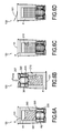
- FIGS. 6A-6D are sequential sectional view of an embodiment of container 100 in use, where FIG. 6A is prior to use, FIG. 6B is during activation; FIG. 6C is during heating of the product; and FIG. 6D is just prior to consumption of the product.
- Container 100 of FIGS. 6A-6D may be generally similar to the embodiments illustrated in FIGS. 1, 2A , 2B , 3, 4 and 5 except as further detailed below. Where possible, similar elements are identified with identical reference numerals in the depiction of the embodiments of FIGS. 1, 2A , 2B , 3, 4 and 5 .
- FIG. 6A shows container 100 in an upright and stored condition.
- FIG. 6B shows container 100 next turned upside down, with a force applied to portion 207.
- the force of portion 207 causes portion 325 to move inwards, resulting in perforator 330 to translate within second compartment 320 and cause piercing elements 409 to puncture membrane 301.
- water within what was second compartment 320 drains into what was first compartment 310 and mix and react with the lime therein. Holes 403 permit perforator 330 to move through the water with reduced resistance and permit the water to easily mix with the lime.
- heat Q evolves from reaction vessel 210 and heats product P.
- FIG. 6C shows container 100 righted for continued heating of product P
- FIG. 6D shows lid 101 removed so that the product may be consumed.
- the independent reaction vessel of the invention could be fixed to a removable lid 101 intended to close the outer body 103.
- This embodiment is particularly favourable as it renders possible to remove the reaction vessel 210 with the lid 101 when opening the container 100.
- the outer body 103 will comprise a shoulder at its upper part.
- the independent reaction vessel 210 disclosed previously is thus placed in the outer body 103 in order that the flange 321 lies on this shoulder when the penetrating part 310 is introduced towards the bottom of the outer body 103 preferably previously filled. Consequently, when the outer body 103 is closed, the base 320 of the reaction vessel 210 is sandwiched between said shoulder and the closing lid 101.
- the reaction vessel 210 lies on the shoulder of the outer body, it is rendered possible to push on the lid 101 that is advantageously flexible for breaking the membrane 301. In this case, the flexible bottom portion 207 is replaced by the flexible lid.
Landscapes
- Engineering & Computer Science (AREA)
- Life Sciences & Earth Sciences (AREA)
- Food Science & Technology (AREA)
- Mechanical Engineering (AREA)
- Cookers (AREA)
- Details Of Rigid Or Semi-Rigid Containers (AREA)
- Food Preservation Except Freezing, Refrigeration, And Drying (AREA)
Applications Claiming Priority (1)
| Application Number | Priority Date | Filing Date | Title |
|---|---|---|---|
| US9170408P | 2008-08-25 | 2008-08-25 |
Publications (1)
| Publication Number | Publication Date |
|---|---|
| EP2159165A1 true EP2159165A1 (fr) | 2010-03-03 |
Family
ID=41226257
Family Applications (1)
| Application Number | Title | Priority Date | Filing Date |
|---|---|---|---|
| EP09167931A Withdrawn EP2159165A1 (fr) | 2008-08-25 | 2009-08-14 | Appareil pour le conditionnement thermique d'un produit |
Country Status (6)
| Country | Link |
|---|---|
| US (1) | US10308416B2 (fr) |
| EP (1) | EP2159165A1 (fr) |
| JP (1) | JP2012500756A (fr) |
| CN (1) | CN102131432A (fr) |
| CA (1) | CA2734298A1 (fr) |
| WO (1) | WO2010022586A1 (fr) |
Cited By (1)
| Publication number | Priority date | Publication date | Assignee | Title |
|---|---|---|---|---|
| US20100047125A1 (en) * | 2008-08-25 | 2010-02-25 | Techithot Limited | Apparatus for thermal conditioning a product |
Families Citing this family (6)
| Publication number | Priority date | Publication date | Assignee | Title |
|---|---|---|---|---|
| CA2889221A1 (fr) * | 2012-11-06 | 2014-05-15 | Heatgenie, Inc. | Dispositifs et procedes de chauffage a arret automatique |
| ITRM20130234A1 (it) * | 2013-04-18 | 2014-10-19 | Stefano Montellanico | Kit per il trattamento termico dei cibi. |
| FI128406B (fi) | 2018-09-04 | 2020-04-30 | Thommy Hellberg | Laite testiveden lämmittämiseksi |
| KR102372161B1 (ko) * | 2020-06-12 | 2022-03-08 | 한재신 | 발열제와 일체화된 일회용식품용기 |
| CN112205857A (zh) * | 2020-09-14 | 2021-01-12 | 华帝股份有限公司 | 一种蒸汽烹饪装置及其控制方法 |
| US12522419B2 (en) | 2021-08-04 | 2026-01-13 | Andrew Jhonnie Spencer | Self-heating or self-cooling system and method |
Citations (9)
| Publication number | Priority date | Publication date | Assignee | Title |
|---|---|---|---|---|
| GB2131542A (en) * | 1982-12-07 | 1984-06-20 | Grog Srl La | A disposable device for self-heating or self-cooling of drinks or foodstuffs by an exothermic or endothermic reaction |
| FR2587608A1 (fr) * | 1985-09-25 | 1987-03-27 | Ukon Murajiroh | Recipient pour le rechauffage ou le refroidissement automatique de boissons ou aliments par une reaction exothermique ou endothermique |
| EP0286382A2 (fr) * | 1987-04-06 | 1988-10-12 | The Coca-Cola Company | Conteneur auto-réfrigérant |
| JPH08217159A (ja) * | 1995-02-17 | 1996-08-27 | Toyo Seikan Kaisha Ltd | 加熱機能付容器 |
| WO1997016101A1 (fr) * | 1995-10-30 | 1997-05-09 | Insta-Heat, Inc. | Recipient a module integre de chauffage ou de refrigeration du contenu |
| US6103280A (en) * | 1997-09-20 | 2000-08-15 | Bass Public Limited Company | Self-cooling containers of beverage and foodstuffs |
| US6141970A (en) * | 1997-09-20 | 2000-11-07 | Bass Public Limited Company | Relating to containers |
| US6178753B1 (en) * | 1999-04-19 | 2001-01-30 | Ontro, Inc. | Container with self-heating module having liquid reactant and breakable reactant barrier at distal end of module |
| US20050198969A1 (en) * | 2004-03-15 | 2005-09-15 | Scudder James A. | Container with integral module for heating or cooling the contents |
Family Cites Families (34)
| Publication number | Priority date | Publication date | Assignee | Title |
|---|---|---|---|---|
| US720435A (en) | 1902-08-07 | 1903-02-10 | George Sidney Jewett | Heating-can for fruit or vegetables, &c. |
| US2289007A (en) | 1939-06-14 | 1942-07-07 | Interchem Corp | Heating mixture for food containers |
| US3970068A (en) * | 1973-05-29 | 1976-07-20 | Shotaro Sato | Heat exchange package for food |
| US4640264A (en) | 1983-10-20 | 1987-02-03 | Tosinobu Yamaguchi | Food and drink warming container |
| JPS61253023A (ja) | 1985-04-04 | 1986-11-10 | 旭化成株式会社 | 加熱容器 |
| EP0244837A1 (fr) | 1986-05-08 | 1987-11-11 | Asahi Kasei Kogyo Kabushiki Kaisha | Récipient autochauffant |
| US4793323A (en) * | 1986-07-16 | 1988-12-27 | Blusei S.P.A. | Single-use self-heating container for liquids and/or solids |
| MX9301122A (es) * | 1992-03-02 | 1994-07-29 | Isidro Genesca Romeu | Envase mixto de extracto en polvo soluble y agua. |
| US5388565A (en) * | 1994-04-01 | 1995-02-14 | Ou; Lih-Horng | Self-heating container system |
| JPH08133348A (ja) | 1994-11-02 | 1996-05-28 | Daiwa Can Co Ltd | 加熱機能付き容器 |
| US5628304A (en) * | 1995-06-22 | 1997-05-13 | G & S Regal Trading Corporation | Self-heating container |
| CN2245409Y (zh) | 1996-03-28 | 1997-01-22 | 张靖庸 | 即热即冷装置 |
| US6029651A (en) | 1999-04-15 | 2000-02-29 | Dorney; Peter | Hot cup adapted to retain fluid contents heated for extended periods of time |
| GB9910984D0 (en) * | 1999-05-13 | 1999-07-14 | Searle Matthew | Atmospheric seal |
| US6266879B1 (en) | 1999-08-26 | 2001-07-31 | Ontro, Inc. | Container with integral module for heating or cooling the contents and method for its manufacture |
| US6267110B1 (en) | 2000-02-25 | 2001-07-31 | Convenience Heating Technologies Ltd. | Disposable heating unit for food containers |
| US6338252B1 (en) * | 2000-03-13 | 2002-01-15 | Smartcup International | Heat transfer container |
| AU2001268764A1 (en) * | 2000-05-29 | 2001-12-11 | Francisco Almoguera | Food and beverage container |
| US6234165B1 (en) * | 2000-08-28 | 2001-05-22 | Kevin A. Creighton | Baby bottle warmer |
| US6601577B2 (en) | 2001-04-06 | 2003-08-05 | Moshe Bouskila | Container assembly for warming beverages and method of forming and using it |
| US6962149B2 (en) * | 2001-05-02 | 2005-11-08 | Expressasia.Com Snd. Bhd. | Insertable thermotic module for self-heating can |
| US7004161B2 (en) | 2001-05-02 | 2006-02-28 | Expressasia Berhad | Insertable thermotic module for self-heating cans |
| EP1481921A1 (fr) * | 2002-01-28 | 2004-12-01 | GENESCA ROMEU, Isidro | Emballage autothermique |
| US6877504B2 (en) | 2003-07-03 | 2005-04-12 | Self-Heating Technologies Corporation | Self-contained temperature-change container assemblies |
| US20050000508A1 (en) * | 2003-07-03 | 2005-01-06 | H. Joshua Schreft | Self-contained temperature-change container assemblies |
| CN2677328Y (zh) | 2004-01-16 | 2005-02-09 | 李峰 | 自体加热的食品/饮料罐 |
| US7025055B2 (en) * | 2004-03-15 | 2006-04-11 | Ontech Delaware Inc. | Tray for selectably heating or cooling the contents |
| AU2005329458A1 (en) | 2005-03-17 | 2006-09-28 | Ontech Delaware Inc. | Container with integral module for heating or cooling the contents |
| AU2006275580B2 (en) | 2005-08-01 | 2012-01-19 | Hot-Can Intellectual Property Sdn. Bhd. | Insertable thermotic module for self-heating can |
| ATE443465T1 (de) | 2005-11-14 | 2009-10-15 | Heat Wave Technologies Llc | Verbesserter selbsterhitzungsbehälter |
| US20070163569A1 (en) | 2006-01-19 | 2007-07-19 | Mark Strachan | Arrangement for and method of selectably changing the temperature of a product by employing a snap action invertible actuator |
| US8402963B2 (en) * | 2006-02-16 | 2013-03-26 | Jose A. Justo | Container with in situ food product mixing and heating |
| CN201010190Y (zh) | 2007-03-12 | 2008-01-23 | 李红军 | 自体加热杯 |
| US10308416B2 (en) * | 2008-08-25 | 2019-06-04 | Techithot Limited | Apparatus for thermal conditioning a product |
-
2008
- 2008-09-24 US US12/236,815 patent/US10308416B2/en not_active Expired - Fee Related
-
2009
- 2009-08-14 EP EP09167931A patent/EP2159165A1/fr not_active Withdrawn
- 2009-08-25 CN CN2009801336125A patent/CN102131432A/zh active Pending
- 2009-08-25 WO PCT/CN2009/000971 patent/WO2010022586A1/fr not_active Ceased
- 2009-08-25 JP JP2011524165A patent/JP2012500756A/ja active Pending
- 2009-08-25 CA CA2734298A patent/CA2734298A1/fr not_active Abandoned
Patent Citations (9)
| Publication number | Priority date | Publication date | Assignee | Title |
|---|---|---|---|---|
| GB2131542A (en) * | 1982-12-07 | 1984-06-20 | Grog Srl La | A disposable device for self-heating or self-cooling of drinks or foodstuffs by an exothermic or endothermic reaction |
| FR2587608A1 (fr) * | 1985-09-25 | 1987-03-27 | Ukon Murajiroh | Recipient pour le rechauffage ou le refroidissement automatique de boissons ou aliments par une reaction exothermique ou endothermique |
| EP0286382A2 (fr) * | 1987-04-06 | 1988-10-12 | The Coca-Cola Company | Conteneur auto-réfrigérant |
| JPH08217159A (ja) * | 1995-02-17 | 1996-08-27 | Toyo Seikan Kaisha Ltd | 加熱機能付容器 |
| WO1997016101A1 (fr) * | 1995-10-30 | 1997-05-09 | Insta-Heat, Inc. | Recipient a module integre de chauffage ou de refrigeration du contenu |
| US6103280A (en) * | 1997-09-20 | 2000-08-15 | Bass Public Limited Company | Self-cooling containers of beverage and foodstuffs |
| US6141970A (en) * | 1997-09-20 | 2000-11-07 | Bass Public Limited Company | Relating to containers |
| US6178753B1 (en) * | 1999-04-19 | 2001-01-30 | Ontro, Inc. | Container with self-heating module having liquid reactant and breakable reactant barrier at distal end of module |
| US20050198969A1 (en) * | 2004-03-15 | 2005-09-15 | Scudder James A. | Container with integral module for heating or cooling the contents |
Cited By (2)
| Publication number | Priority date | Publication date | Assignee | Title |
|---|---|---|---|---|
| US20100047125A1 (en) * | 2008-08-25 | 2010-02-25 | Techithot Limited | Apparatus for thermal conditioning a product |
| US10308416B2 (en) * | 2008-08-25 | 2019-06-04 | Techithot Limited | Apparatus for thermal conditioning a product |
Also Published As
| Publication number | Publication date |
|---|---|
| US20100047125A1 (en) | 2010-02-25 |
| CN102131432A (zh) | 2011-07-20 |
| JP2012500756A (ja) | 2012-01-12 |
| WO2010022586A1 (fr) | 2010-03-04 |
| US10308416B2 (en) | 2019-06-04 |
| CA2734298A1 (fr) | 2010-03-04 |
Similar Documents
| Publication | Publication Date | Title |
|---|---|---|
| AU2002256320B2 (en) | Insertable thermotic module for self-heating can | |
| EP2159165A1 (fr) | Appareil pour le conditionnement thermique d'un produit | |
| CN100402392C (zh) | 自加热容器 | |
| US20050000507A1 (en) | Self-contained temperature-change container assemblies | |
| KR20020043608A (ko) | 자체-가열 또는 자체-냉각 콘테이너 | |
| WO2007059122A1 (fr) | Recipient auto-chauffant | |
| EP1561076A4 (fr) | Module thermique inserable pour boites autochauffantes | |
| WO2000050315A1 (fr) | Recipient autochauffants ou autorefroidissants | |
| US20050051156A1 (en) | Reagent mixtures for self-contained temperature-change container assemblies | |
| EP1292511B1 (fr) | Recipient pour aliments et boissons | |
| WO2016162729A1 (fr) | Gobelet auto-chauffant jetable | |
| US6502407B1 (en) | Self-heating or self-cooling containers | |
| US20060153955A1 (en) | Food product warming or cooling package | |
| CN101784461B (zh) | 可自加热容器 | |
| WO2017122047A1 (fr) | Module autochauffant et procédé d'installation | |
| RU2281897C2 (ru) | Саморазогревающаяся упаковка | |
| JPH0525550Y2 (fr) | ||
| GB2404010A (en) | Self-contained temperature-change container assemblies | |
| CN105668014A (zh) | 食品包装自加热或制冷装置 | |
| RU2438947C2 (ru) | Саморазогревающаяся емкость | |
| PL245861B1 (pl) | Samopodgrzewające się opakowanie do żywności | |
| RU44479U1 (ru) | Устройство для изменения температуры преимущественно напитков | |
| JPH0513326Y2 (fr) | ||
| KR20140068294A (ko) | 발열체를 구비한 음료 박스용기 | |
| JP2016182309A (ja) | 加熱用容器 |
Legal Events
| Date | Code | Title | Description |
|---|---|---|---|
| PUAI | Public reference made under article 153(3) epc to a published international application that has entered the european phase |
Free format text: ORIGINAL CODE: 0009012 |
|
| AK | Designated contracting states |
Kind code of ref document: A1 Designated state(s): AT BE BG CH CY CZ DE DK EE ES FI FR GB GR HR HU IE IS IT LI LT LU LV MC MK MT NL NO PL PT RO SE SI SK SM TR |
|
| AX | Request for extension of the european patent |
Extension state: AL BA RS |
|
| 17P | Request for examination filed |
Effective date: 20100903 |
|
| 17Q | First examination report despatched |
Effective date: 20100924 |
|
| STAA | Information on the status of an ep patent application or granted ep patent |
Free format text: STATUS: THE APPLICATION IS DEEMED TO BE WITHDRAWN |
|
| 18D | Application deemed to be withdrawn |
Effective date: 20140923 |