EP2159168A1 - Müllschlucker zum automatischen und getrennten Sammeln von Müll - Google Patents
Müllschlucker zum automatischen und getrennten Sammeln von Müll Download PDFInfo
- Publication number
- EP2159168A1 EP2159168A1 EP20090305734 EP09305734A EP2159168A1 EP 2159168 A1 EP2159168 A1 EP 2159168A1 EP 20090305734 EP20090305734 EP 20090305734 EP 09305734 A EP09305734 A EP 09305734A EP 2159168 A1 EP2159168 A1 EP 2159168A1
- Authority
- EP
- European Patent Office
- Prior art keywords
- column
- module
- waste
- plate
- drain according
- Prior art date
- Legal status (The legal status is an assumption and is not a legal conclusion. Google has not performed a legal analysis and makes no representation as to the accuracy of the status listed.)
- Withdrawn
Links
- 238000005303 weighing Methods 0.000 claims abstract description 11
- 239000002699 waste material Substances 0.000 claims description 80
- 239000010813 municipal solid waste Substances 0.000 claims description 6
- 230000005540 biological transmission Effects 0.000 claims description 4
- 230000000694 effects Effects 0.000 claims description 4
- 238000006073 displacement reaction Methods 0.000 claims description 3
- 238000004891 communication Methods 0.000 claims description 2
- 239000000645 desinfectant Substances 0.000 claims description 2
- 230000014759 maintenance of location Effects 0.000 claims description 2
- 238000009434 installation Methods 0.000 description 11
- 238000003780 insertion Methods 0.000 description 3
- 230000037431 insertion Effects 0.000 description 3
- 230000010354 integration Effects 0.000 description 3
- 238000007726 management method Methods 0.000 description 3
- 238000010276 construction Methods 0.000 description 2
- 238000000605 extraction Methods 0.000 description 2
- 230000005484 gravity Effects 0.000 description 2
- 238000004659 sterilization and disinfection Methods 0.000 description 2
- 238000003466 welding Methods 0.000 description 2
- 238000013459 approach Methods 0.000 description 1
- 238000012550 audit Methods 0.000 description 1
- 230000000903 blocking effect Effects 0.000 description 1
- 230000006835 compression Effects 0.000 description 1
- 238000007906 compression Methods 0.000 description 1
- 238000012937 correction Methods 0.000 description 1
- 238000005202 decontamination Methods 0.000 description 1
- 230000003588 decontaminative effect Effects 0.000 description 1
- 230000007547 defect Effects 0.000 description 1
- 238000013461 design Methods 0.000 description 1
- 235000013305 food Nutrition 0.000 description 1
- 239000010922 glass waste Substances 0.000 description 1
- 238000005259 measurement Methods 0.000 description 1
- 239000013502 plastic waste Substances 0.000 description 1
- 230000011664 signaling Effects 0.000 description 1
- 238000011144 upstream manufacturing Methods 0.000 description 1
- 235000013311 vegetables Nutrition 0.000 description 1
- XLYOFNOQVPJJNP-UHFFFAOYSA-N water Substances O XLYOFNOQVPJJNP-UHFFFAOYSA-N 0.000 description 1
Images


Classifications
-
- B—PERFORMING OPERATIONS; TRANSPORTING
- B65—CONVEYING; PACKING; STORING; HANDLING THIN OR FILAMENTARY MATERIAL
- B65F—GATHERING OR REMOVAL OF DOMESTIC OR LIKE REFUSE
- B65F1/00—Refuse receptacles; Accessories therefor
- B65F1/0093—Refuse receptacles; Accessories therefor specially adapted for collecting refuse from arrangements in buildings
-
- E—FIXED CONSTRUCTIONS
- E04—BUILDING
- E04F—FINISHING WORK ON BUILDINGS, e.g. STAIRS, FLOORS
- E04F17/00—Vertical ducts; Channels, e.g. for drainage
- E04F17/10—Arrangements in buildings for the disposal of refuse
- E04F17/12—Chutes
-
- B—PERFORMING OPERATIONS; TRANSPORTING
- B65—CONVEYING; PACKING; STORING; HANDLING THIN OR FILAMENTARY MATERIAL
- B65F—GATHERING OR REMOVAL OF DOMESTIC OR LIKE REFUSE
- B65F1/00—Refuse receptacles; Accessories therefor
- B65F1/0033—Refuse receptacles; Accessories therefor specially adapted for segregated refuse collecting, e.g. receptacles with several compartments; Combination of receptacles
- B65F2001/008—Means for automatically selecting the receptacle in which refuse should be placed
-
- B—PERFORMING OPERATIONS; TRANSPORTING
- B65—CONVEYING; PACKING; STORING; HANDLING THIN OR FILAMENTARY MATERIAL
- B65F—GATHERING OR REMOVAL OF DOMESTIC OR LIKE REFUSE
- B65F2210/00—Equipment of refuse receptacles
- B65F2210/184—Weighing means
-
- Y—GENERAL TAGGING OF NEW TECHNOLOGICAL DEVELOPMENTS; GENERAL TAGGING OF CROSS-SECTIONAL TECHNOLOGIES SPANNING OVER SEVERAL SECTIONS OF THE IPC; TECHNICAL SUBJECTS COVERED BY FORMER USPC CROSS-REFERENCE ART COLLECTIONS [XRACs] AND DIGESTS
- Y02—TECHNOLOGIES OR APPLICATIONS FOR MITIGATION OR ADAPTATION AGAINST CLIMATE CHANGE
- Y02W—CLIMATE CHANGE MITIGATION TECHNOLOGIES RELATED TO WASTEWATER TREATMENT OR WASTE MANAGEMENT
- Y02W30/00—Technologies for solid waste management
- Y02W30/10—Waste collection, transportation, transfer or storage, e.g. segregated refuse collecting, electric or hybrid propulsion
Definitions
- the invention relates to the technical sector of the treatment of waste and rubble in buildings and apartment buildings in particular.
- the sorting of food, vegetable, glass or plastic waste and other detritus of all kinds is the object of a very important awareness campaign among consumers to ensure, by providing equipment and containers, better management of the aforementioned waste.
- the installation of automatic sorting and removal of waste and rubble in buildings is of the type comprising on each floor of a building a hatch (1) whose opening is controlled by a selection box (2) comprising as many contactors as there are families of waste or rubble to be evacuated in specific receptacles located at the bottom of the building. It comprises on the one hand a collector device (4) mounted in a box (7) on the base and communicating with a rotary chute (9), driven by a transmission (8, 10, 11) controlled by actuation of one of the contactors from the selection housing (2) to the floor, and on the other hand, interlocking sleeves (5) sealingly connecting the hatches (1) and the collector (4), as and when the elevation of the building.
- the patent is also known DE 2322420 .
- the document DE 2322420 discloses a waste vacuum installation incorporating in a column (1) modules (5) for receiving waste bags (a).
- Each module is inserted in the wall wall of the building concerned and is housed and overflowing internally in the column.
- the module provides at its base a retractable bottom in the form of a hatch (15) hinged on an axis (14) controlled by a handle (17).
- the bag of waste falls obliquely to be evacuated in the column.
- the bag of waste which by definition never has the same final configuration being filled according to the mass of waste, their volume and their shape, is subjected to a tilting and sliding effect along the profile of the hatch so that it is likely to abut against the opposite wall of the discharge column.
- the automated sorting waste bin of the type comprising a waste disposal column in communication with one or more access doors and waste introduction located at different levels, a housing of control ensuring the management of the opening-closing of the access doors, the waste disposal column being arranged at the location of each of the floors of the dwelling concerned for receiving modules opening into said column, said modules being arranged to allow the reception of waste bags or waste themselves to be evacuated in the column under the effect of actuating a pivoted articulated means, is remarkable in that each module is integrated in the continuity of the column d waste disposal in a configuration similar to the configuration of the column or parts of columns to come and fit together and articulate in a co in a situation of non-use, and in that each module is arranged with at least one tray in a horizontal plane receiving the bag of waste to be evacuated in a vertical position and allowing its evacuation of the column by simply falling vertically, and in that it comprises a weighing device integrated in the module calculating the weight of the mass of waste to be evacuated and secured
- the automated sorting bin according to the invention differs from the prior art represented by the patents FR 2807083 and 2821873 by the design at each stage of a building, house or building including a waste-junk system by the integration of modules (M) which are arranged to be integrated directly into the waste disposal column without inclined chute system in relationship with the access hatch, the modules being arranged to allow the reception of the bags of waste or the waste themselves in a vertical position of easy access to be then discharged into the chute vertically by gravity under the effect of actuating an articulated pivoting means in a horizontal plane and releasing the column to allow said evacuation.
- access to a module is through a remote control box and recognition and identification or blocking in solicitation phase access to other modules located at levels of different floors.
- the integration of the module (M) in a column (C) for the evacuation of waste is represented, said module being movable transversely and horizontally by means of control and traction means (20) associated with the door (P) from the hatch.
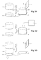
- the module (M) has a movable bottom (M1) which in the closed position allows the retention of waste or garbage bags, and which can be moved horizontally or be a hatch itself for the disposal of waste in the column. It has thus been shown diagrammatically to Figures 2.1, 2.2, and 2.3 the principle of this implementation.
- the Figures 3.1, 3.2 and 3.3 illustrate an implementation of this concept. It is represented by (C1-C2) the two parts of fixed columns between which the module (M) will move.
- the module consists of two components, namely a fixed plate (21) and a movable basket (22) mounted and articulated in rotation on an axis (23) with motorized device.
- the access door is always represented by (P).
- the movable basket has a closed cylindrical configuration similar to the configuration of the column or parts of columns (C1-C2) to come and fit in a continuity in case of non-use.
- the basket (22) is open at its bottom.
- the figure 3.1 represents the movement of the basket (22) or the receiving plate according to the arrow F1.
- the access door remains closed. The movement was authorized by the control on the housing (B) remote control. In this situation, it is clear that the column (C) waste disposal is no longer continuous because the module comprising the basket has moved for filling.
- the door is unlocked and the user can put the waste or the garbage bag in the basket.
- the next phase consists in repositioning the module (M) within the column, in order to evacuate the waste collected in the basket.
- the latter is moved again by its control means by driving the bag of trash on the fixed plate until the present in continuity of the column and thus releasing the fixed plate (21). Waste disposal takes place after closing the door according to an established schedule.
- the fixed plate (21) has been symbolically represented in a square geometrical form, but this plate in practice has a more complex geometrical shape while being fixed to the column part (C2) and allowing the displacement circulatory basket from one position to another, while maintaining contact with the basket until the latter integrates its position within the waste disposal column.
- the trash bag is positioned outside the column and then translated to it under the withdrawal action and the refitting of the movable basket.
- the volume of the basket (22) determines the volume of the bag of garbage and waste and can not go beyond the capacity of the basket.
- the access door (P) is directly connected to said module with a hinge.
- the bottom plate (25) is always movable horizontally with the aid of guide means and appropriate motorized means.
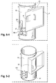
- the module with its bottom is a kind of large volume chamber allowing its filling of waste or bags of waste which will then be evacuated after closing the door by moving the plate and the opening of the column waste disposal. So, the figure 4.2 represents the positioning of the waste in the module and on the bottom plate, and the figure 4.3 the displacement of the plateau and the evacuation of the waste by vertical fall.
- the module (M) constitutes an assembly with the implementation of a movable plate (25) of the type exposed to Figures 4.1, 4.2, 4.3 .
- the module (M) receives a connecting box (26) parallelepiped for example and fixed by welding, welding mechanic, bonding or other module audit.
- the access door (P) is located on the connecting box, as well as the control box (B) and operator identification.
- the module has a corresponding opening for the introduction of waste or bags of waste.
- the module (M) In its lower position, the module (M) has a slot (M2) horizontal for the passage of the plate (25) articulated constituting the bottom of the module.
- the plateau which is circular for correspond to the section of the module can pivot relative to a hinge axis (27).
- the motor unit (28) is shown by way of example in the extension of the pivot axis of the plate.
- the module (M) is always integrated in the column (C) between the upper (C1) and lower duct elements.
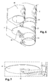
- the module comprises two fixed rings (C3-C4) constituting column parts (C) between which will move the movable basket portion (22) of cylindrical section and establishing a continuity of the column.
- the upper fixed ring (C3) is fixed by fitting or otherwise to the upper duct of the column and likewise for the lower fixed ring (24) with the underlying lower duct of the column.
- This fixed ring (C4) is instead arranged to form the support of the fixed plate (21).
- the latter has a complex geometric shape with a neck portion fitting and attaching to the upper part of the ring (C4) and an overflowing portion in water drop so that it always constitutes the bottom of the basket ( 22) when the latter moves for the reception of waste and then their evacuation.
- the basket loaded with waste will resume its place in the continuity of the column and allow by tilting and gravity the evacuation of waste down.
- a weighing device (30) to have a perfect knowledge of the weight of the mass of waste to be evacuated.
- This weighing device is connected by transmission means to the control box for transmit the collected information and assign it to the user concerned who has previously identified himself to carry out this disposal of waste.
- the weighing device is located under the stationary platen (21) or the movable platen (25), in the center of it to make a correct measurement. As shown figure 7 in the case of the movable plate, the weighing device is positioned horizontally to said plate in view of the evacuation phases. It should be noted that the weighing device is likely to operate with litter weight limits to be evacuated and in case of overload the system is blocked with an alarm or signaling for overload correction.
- the module is equipped with several nozzles (32) for the projection of disinfectants in the column.
- These nozzles can also be arranged on the connection ducts of the column located on either side and surrounding the module. These nozzles are fixed in any appropriate manner on the module and / or the receiving ducts and are powered by cartridges or others. Their intervention is carried out each time the module is used and is controlled and operated by a duly established program.
- the invention has many advantages.
- the realization of the modules thus described makes it possible to adapt them both in new column installations and in integration into existing columns.
- the dimensions of the modules in terms of section can be adapted to the dimensions of the existing columns.
- the disposal of waste for disposal is very practical. It is done vertically and there is no more phenomena of stuffing, compression of waste and blockage of the trap door.
- the emptying device according to the invention is integrated into the installations new buildings planned for this purpose, and thus a rehabilitation of buildings from the outside by constituting an autonomous enclosure.
- the implementation is very practical with possibilities of choosing the installation according to the proposed variants according to the needs of the users and also the costs and therefore the budgets allocated.
- the invention allows automated and secure management of waste and also allows allocation of waste treatment costs to each user.
Landscapes
- Engineering & Computer Science (AREA)
- Architecture (AREA)
- Structural Engineering (AREA)
- Mechanical Engineering (AREA)
- Civil Engineering (AREA)
- Processing Of Solid Wastes (AREA)
- Refuse Collection And Transfer (AREA)
Applications Claiming Priority (1)
| Application Number | Priority Date | Filing Date | Title |
|---|---|---|---|
| FR0855844A FR2935367B1 (fr) | 2008-09-01 | 2008-09-01 | Vidoir a tri selectif automatise. |
Publications (1)
| Publication Number | Publication Date |
|---|---|
| EP2159168A1 true EP2159168A1 (de) | 2010-03-03 |
Family
ID=40227960
Family Applications (1)
| Application Number | Title | Priority Date | Filing Date |
|---|---|---|---|
| EP20090305734 Withdrawn EP2159168A1 (de) | 2008-09-01 | 2009-08-05 | Müllschlucker zum automatischen und getrennten Sammeln von Müll |
Country Status (2)
| Country | Link |
|---|---|
| EP (1) | EP2159168A1 (de) |
| FR (1) | FR2935367B1 (de) |
Cited By (2)
| Publication number | Priority date | Publication date | Assignee | Title |
|---|---|---|---|---|
| CN107150879A (zh) * | 2017-05-09 | 2017-09-12 | 成都市容德建筑劳务有限公司 | 一种楼宇物流系统 |
| CN114852547A (zh) * | 2022-04-28 | 2022-08-05 | 济南一建集团有限公司 | 一种绿色建筑垃圾回收通道 |
Families Citing this family (1)
| Publication number | Priority date | Publication date | Assignee | Title |
|---|---|---|---|---|
| FR2967405A1 (fr) | 2010-11-12 | 2012-05-18 | Triologis | Installation de collecte selective de dechets en apport volontaire |
Citations (5)
| Publication number | Priority date | Publication date | Assignee | Title |
|---|---|---|---|---|
| DE2322420A1 (de) | 1973-05-04 | 1974-11-14 | Keller & Knappich Augsburg | Muelleinwurfvorrichtung in muellabwurfschaechte |
| GB2290039A (en) * | 1994-06-08 | 1995-12-13 | Korea Energy Research Inst | Waste disposal chute for multi-storey building |
| US5678975A (en) * | 1994-12-22 | 1997-10-21 | Fuji Jukogyo Kabushiki Kaisha | Waste container throw-in system for buildings |
| FR2807083A1 (fr) | 2000-04-03 | 2001-10-05 | Hortig T C Air | Installation d'evacuation des dechets menagers dans les immeubles |
| FR2821873A1 (fr) | 2001-03-09 | 2002-09-13 | Hortig T C Air | Installation de triage automatique et d'evacuation de dechets et gravats dans les batiments |
-
2008
- 2008-09-01 FR FR0855844A patent/FR2935367B1/fr not_active Expired - Fee Related
-
2009
- 2009-08-05 EP EP20090305734 patent/EP2159168A1/de not_active Withdrawn
Patent Citations (5)
| Publication number | Priority date | Publication date | Assignee | Title |
|---|---|---|---|---|
| DE2322420A1 (de) | 1973-05-04 | 1974-11-14 | Keller & Knappich Augsburg | Muelleinwurfvorrichtung in muellabwurfschaechte |
| GB2290039A (en) * | 1994-06-08 | 1995-12-13 | Korea Energy Research Inst | Waste disposal chute for multi-storey building |
| US5678975A (en) * | 1994-12-22 | 1997-10-21 | Fuji Jukogyo Kabushiki Kaisha | Waste container throw-in system for buildings |
| FR2807083A1 (fr) | 2000-04-03 | 2001-10-05 | Hortig T C Air | Installation d'evacuation des dechets menagers dans les immeubles |
| FR2821873A1 (fr) | 2001-03-09 | 2002-09-13 | Hortig T C Air | Installation de triage automatique et d'evacuation de dechets et gravats dans les batiments |
Cited By (4)
| Publication number | Priority date | Publication date | Assignee | Title |
|---|---|---|---|---|
| CN107150879A (zh) * | 2017-05-09 | 2017-09-12 | 成都市容德建筑劳务有限公司 | 一种楼宇物流系统 |
| CN107150879B (zh) * | 2017-05-09 | 2024-04-16 | 南京空浪科技有限公司 | 一种楼宇物流系统 |
| CN114852547A (zh) * | 2022-04-28 | 2022-08-05 | 济南一建集团有限公司 | 一种绿色建筑垃圾回收通道 |
| CN114852547B (zh) * | 2022-04-28 | 2023-04-07 | 济南一建集团有限公司 | 一种绿色建筑垃圾回收通道 |
Also Published As
| Publication number | Publication date |
|---|---|
| FR2935367B1 (fr) | 2013-05-24 |
| FR2935367A1 (fr) | 2010-03-05 |
Similar Documents
| Publication | Publication Date | Title |
|---|---|---|
| EP0242274B1 (de) | Sanitäreinheit mit automatischer Reinigung | |
| EP0507687B1 (de) | Sanitärtoilette zur Trennung und Sammlung vom radioaktiven Urin | |
| EP0262275B1 (de) | Vorrichtung zum Säubern eines Klosettsitzes | |
| EP2159168A1 (de) | Müllschlucker zum automatischen und getrennten Sammeln von Müll | |
| FR2710329A1 (fr) | Collecteur de déchets urbains. | |
| FR2694273A1 (fr) | Station intérieure familiale ou collective et module spécifique la composant pour la collecte sélective des déchets domestiques. | |
| EP0702655A1 (de) | Vorrichtung zum sortieren von müll in einem hochhaus | |
| EP0773175A1 (de) | Sammelbehälter für spezifische Abfälle,insbesondere medizinische Abfälle | |
| FR2857948A1 (fr) | Conteneur destine a la collecte des dechets et enceinte le refermant | |
| FR2959161A1 (fr) | Conteneur de collecte autorisant le compactage des dechets | |
| FR2630415A1 (fr) | Conteneur a ordures | |
| EP2452897A1 (de) | Anlage zur selektiven Müllsammlung | |
| EP0329574B1 (de) | Anlage zum Beseitigen von Gegenständen durch Einfüllen in einen Behälter | |
| FR2978960A1 (fr) | Conteneur de collecte des dechets dote d'un systeme d'actionnement de trappes perfectionne | |
| FR2758354A1 (fr) | Systeme de transport d'ordures menageres | |
| FR2821873A1 (fr) | Installation de triage automatique et d'evacuation de dechets et gravats dans les batiments | |
| EP3650372A1 (de) | Sammelsystem von lebensmittelabfällen für gemeinschaftsverpflegungseinrichtungen, das ein wiegen der abfälle umfasst | |
| FR2537638A1 (fr) | Dispositif de vide-ordures | |
| FR2932465A1 (fr) | Dispositif de plate-forme d'accueil pour le vidage et le lavage des vehicules de nettoiement des chaussees | |
| WO2002062618A1 (fr) | Installation d'un transfert de fonds entre un site et un vehicule | |
| EP1097884A1 (de) | In einen Kipp-Lastwagen intergrierter Vorrichtung zum Sammeln und selektiven Abladen von mindestens zwei Arten von Abfällen | |
| FR3127235A1 (fr) | installation sanitaire. | |
| FR2538831A1 (fr) | Evacuateur-compacteur d'ordures menageres pour habitations individuelles | |
| FR2898592A1 (fr) | Dispositif d'ouverture et de fermeture d'un conteneur | |
| FR2712572A1 (fr) | Conteneur pour le stockage sélectif de déchets. |
Legal Events
| Date | Code | Title | Description |
|---|---|---|---|
| PUAI | Public reference made under article 153(3) epc to a published international application that has entered the european phase |
Free format text: ORIGINAL CODE: 0009012 |
|
| AK | Designated contracting states |
Kind code of ref document: A1 Designated state(s): AT BE BG CH CY CZ DE DK EE ES FI FR GB GR HR HU IE IS IT LI LT LU LV MC MK MT NL NO PL PT RO SE SI SK SM TR |
|
| 17P | Request for examination filed |
Effective date: 20100625 |
|
| 17Q | First examination report despatched |
Effective date: 20121015 |
|
| STAA | Information on the status of an ep patent application or granted ep patent |
Free format text: STATUS: THE APPLICATION IS DEEMED TO BE WITHDRAWN |
|
| 18D | Application deemed to be withdrawn |
Effective date: 20130226 |