EP2159199A2 - Dispositif et procédé de fabrication de plaques de verre précontraintes thermiquement et plaque de verre précontrainte thermiquement - Google Patents
Dispositif et procédé de fabrication de plaques de verre précontraintes thermiquement et plaque de verre précontrainte thermiquement Download PDFInfo
- Publication number
- EP2159199A2 EP2159199A2 EP20090167734 EP09167734A EP2159199A2 EP 2159199 A2 EP2159199 A2 EP 2159199A2 EP 20090167734 EP20090167734 EP 20090167734 EP 09167734 A EP09167734 A EP 09167734A EP 2159199 A2 EP2159199 A2 EP 2159199A2
- Authority
- EP
- European Patent Office
- Prior art keywords
- glass
- measuring
- heating
- coating
- cooling
- Prior art date
- Legal status (The legal status is an assumption and is not a legal conclusion. Google has not performed a legal analysis and makes no representation as to the accuracy of the status listed.)
- Withdrawn
Links
- 239000011521 glass Substances 0.000 title claims abstract description 201
- 238000000034 method Methods 0.000 title claims description 27
- 238000010438 heat treatment Methods 0.000 claims abstract description 88
- 238000001816 cooling Methods 0.000 claims abstract description 68
- 238000000576 coating method Methods 0.000 claims abstract description 48
- 230000003287 optical effect Effects 0.000 claims abstract description 47
- 239000011248 coating agent Substances 0.000 claims abstract description 43
- 238000005259 measurement Methods 0.000 claims abstract description 33
- 230000010287 polarization Effects 0.000 claims abstract description 27
- 239000005341 toughened glass Substances 0.000 claims description 43
- 230000033001 locomotion Effects 0.000 claims description 13
- 230000000475 sunscreen effect Effects 0.000 claims description 5
- 239000000516 sunscreening agent Substances 0.000 claims description 5
- 230000005855 radiation Effects 0.000 claims description 4
- 239000012720 thermal barrier coating Substances 0.000 claims description 3
- 238000004519 manufacturing process Methods 0.000 abstract description 7
- 230000001419 dependent effect Effects 0.000 abstract description 5
- 230000000694 effects Effects 0.000 description 14
- 238000009826 distribution Methods 0.000 description 12
- 230000008569 process Effects 0.000 description 12
- 239000005328 architectural glass Substances 0.000 description 7
- 230000006870 function Effects 0.000 description 6
- 239000000463 material Substances 0.000 description 6
- 229910052751 metal Inorganic materials 0.000 description 6
- 239000002184 metal Substances 0.000 description 6
- 239000005336 safety glass Substances 0.000 description 5
- 238000005496 tempering Methods 0.000 description 5
- 230000008859 change Effects 0.000 description 4
- 150000004767 nitrides Chemical class 0.000 description 4
- 230000006378 damage Effects 0.000 description 3
- 239000005357 flat glass Substances 0.000 description 3
- 239000005329 float glass Substances 0.000 description 3
- 238000001755 magnetron sputter deposition Methods 0.000 description 3
- 230000003595 spectral effect Effects 0.000 description 3
- 238000000151 deposition Methods 0.000 description 2
- 230000008021 deposition Effects 0.000 description 2
- 238000009413 insulation Methods 0.000 description 2
- 230000004048 modification Effects 0.000 description 2
- 238000012986 modification Methods 0.000 description 2
- 238000005457 optimization Methods 0.000 description 2
- 230000036316 preload Effects 0.000 description 2
- 230000037072 sun protection Effects 0.000 description 2
- 208000027418 Wounds and injury Diseases 0.000 description 1
- 238000004458 analytical method Methods 0.000 description 1
- 239000005391 art glass Substances 0.000 description 1
- 230000002238 attenuated effect Effects 0.000 description 1
- 238000005452 bending Methods 0.000 description 1
- 230000033228 biological regulation Effects 0.000 description 1
- 230000005540 biological transmission Effects 0.000 description 1
- 238000004364 calculation method Methods 0.000 description 1
- 230000007613 environmental effect Effects 0.000 description 1
- 238000001914 filtration Methods 0.000 description 1
- 239000012634 fragment Substances 0.000 description 1
- 208000014674 injury Diseases 0.000 description 1
- 238000000691 measurement method Methods 0.000 description 1
- 239000000203 mixture Substances 0.000 description 1
- 230000010355 oscillation Effects 0.000 description 1
- 230000008447 perception Effects 0.000 description 1
- 230000035939 shock Effects 0.000 description 1
- 229910052709 silver Inorganic materials 0.000 description 1
- 239000004332 silver Substances 0.000 description 1
- 238000004088 simulation Methods 0.000 description 1
- 238000004544 sputter deposition Methods 0.000 description 1
- 230000002123 temporal effect Effects 0.000 description 1
- 230000009466 transformation Effects 0.000 description 1
- 239000012780 transparent material Substances 0.000 description 1
- 238000001771 vacuum deposition Methods 0.000 description 1
Images


Classifications
-
- C—CHEMISTRY; METALLURGY
- C03—GLASS; MINERAL OR SLAG WOOL
- C03B—MANUFACTURE, SHAPING, OR SUPPLEMENTARY PROCESSES
- C03B27/00—Tempering or quenching glass products
- C03B27/04—Tempering or quenching glass products using gas
- C03B27/0417—Controlling or regulating for flat or bent glass sheets
-
- C—CHEMISTRY; METALLURGY
- C03—GLASS; MINERAL OR SLAG WOOL
- C03B—MANUFACTURE, SHAPING, OR SUPPLEMENTARY PROCESSES
- C03B27/00—Tempering or quenching glass products
- C03B27/04—Tempering or quenching glass products using gas
- C03B27/0413—Stresses, e.g. patterns, values or formulae for flat or bent glass sheets
-
- G—PHYSICS
- G01—MEASURING; TESTING
- G01L—MEASURING FORCE, STRESS, TORQUE, WORK, MECHANICAL POWER, MECHANICAL EFFICIENCY, OR FLUID PRESSURE
- G01L1/00—Measuring force or stress, in general
- G01L1/24—Measuring force or stress, in general by measuring variations of optical properties of material when it is stressed, e.g. by photoelastic stress analysis using infrared, visible light, ultraviolet
Definitions
- the invention relates to an apparatus and a method for producing thermally toughened glass sheets. Furthermore, the invention relates to a thermally toughened glass pane, in particular a flat glass pane for use as architectural glass.
- Thermal tempering creates a permanent tensile stress in the interior of the glass by means of a heat treatment and a permanent compressive stress on the surfaces and edges.
- thermally toughened glass sheets lie in the surface compressive stresses impressed by the thermal tempering process in the glass, which leads to a significantly increased bending tensile strength of the glass sheets thus produced compared to untreated glass sheets.
- Thermally toughened glass therefore has a higher mechanical damage threshold than normal float glass. The strength of the glass increases approximately to the level of the impressed in the glass permanent surface compressive stress.
- a fully thermally toughened glass pane so-called toughened safety glass (ESG) should generally have a surface preload of at least 69 MPa.
- Partially tempered glass (TVG) is generally referred to when surface compressive stresses of 24-52 MPa are achieved.
- thermally toughened glass sheets have a better resistance to temperature differences in the disk surface, combined with a higher thermal shock resistance.
- the toughened safety glass over teilvorgespanntem glass additionally has the desired property that it decays in mechanical damage beyond the load limits in a variety of small fragments that pose a much lower risk of injury than broken float glass panes or teilvorgespannte glasses.
- responsible for the feinkrümelige shard in the event of a break is frozen in the middle plane of the single-pane safety glass tension.
- the thermal tempering of glass sheets is generally carried out by first heating the entire glass sheet to the softening point of the glass (about 100 K above the transformation point of the glass). Following this, the glass is subjected to a rapid cooling from the surface.
- the treated in this way according to the prior art glass panels often show more or less strong when illuminated with at least partially polarized light unwanted color effects. These color effects are often visible even under natural lighting conditions, such as occur in overcast skies, for example, on a glass facade.
- the reason for the occurrence of these color effects are birefringence phenomena, which occur due to the impressed by the thermal tempering in the glass two-dimensional stress state.
- the voltage-induced birefringence has the consequence that a light beam passing through the glass undergoes a change in its polarization state.
- the patent DE 197 20 330 C1 discloses a method and apparatus for measuring strains in glass panes using a stray light method in which a polarization periodically between a linearly and circularly changing monochromatic beam is obliquely directed to the glass plate and the stray light generated within the glass sheet along the path of the light beam is detected by a video camera becomes.
- a combination of two or more panes of glass in one or more elements one behind the other enhances the visibility of the color effects.
- the color effects increase with increasing thickness of the glasses, especially under oblique incidence of light. Even with disks arranged at an angle to each other, resulting multiple reflections which cause partial polarization of the light can enhance this effect, e.g. in shower cubicles.
- a coating for example a sunscreen or heat protection coating
- thermally toughened glass is for example from the document EP 1529761 A1 known.
- the filtering effect of such coatings which have a spectral dependence of the reflectance on the wavelength and the polarization direction of the incident light, can lead to a wavelength-dependent amplified or attenuated perception of the reflected light. This leads to higher color contrasts between areas of different glass tensions, whereby the existing polarization fields are further highlighted in their visibility.
- the invention has for its object to provide an apparatus and a method for producing thermally toughened glass sheets, which are suitable for the production of glass panes with a reduced optical anisotropy. Furthermore, a thermally toughened glass pane is to be specified in which unwanted color effects caused by optical anisotropy are reduced. In particular, should even with large and / or coated glass panes no visible color effects occur.
- a device for producing thermally toughened glass panes comprises a heating device, a cooling device and a measuring device which is suitable for measuring the optical anisotropy of a glass pane at a multiplicity of measuring points distributed over the surface of the glass pane.
- the plurality of measuring points is distributed in a two-dimensional grid over the surface of the glass sheet.
- the device advantageously comprises a control unit which is suitable for controlling the heating device and / or the cooling device on the basis of the measured data determined by the measuring device.
- the invention makes use of the knowledge that measurement and regulation of the surface temperature of the glass pane in the heating device and / or the cooling device, in which the glass sheets are thermally pre-stressed, alone is insufficient to homogeneity of the temperature distribution in the volume of the glass pane over the entire surface of the glass pane too guarantee. Rather, it has proven to be advantageous to measure the optical anisotropy of the glass pane at a plurality of measuring points, which are distributed over the surface of the glass pane, for example in a two-dimensional grid, and to use the measurement data obtained in this way to heat up and to control the cooling of the glass sheet in the heating device and the cooling device.
- the measurement of the optical anisotropy at the plurality of measuring points distributed over the surface of the glass pane is preferably carried out by measuring the polarization state of light of a polarized light source after the passage of the polarized light through the glass pane.
- the measurement of the optical anisotropy can be based on the so-called Sénarmont method.
- a linearly polarized light beam is preferably directed orthogonally onto the glass pane and oriented such that the polarization direction runs parallel to the angle bisector of the mutually perpendicular main stress directions in the glass pane.
- This linearly polarized light beam undergoes a modification of the polarization state when passing through the glass pane, which is affected by refractive index fluctuations due to mechanical stresses.
- the change in the state of polarization is analyzed by means of a ⁇ / 4 plate rotatably mounted in the beam path and an analyzer, which is a rotatable polarizing filter, in combination with a detector and from the optical path difference for the two polarization directions, which are parallel to the both main directions of tension, determined.
- the measuring device preferably contains a light source, a polarizer, a ⁇ / 4 plate, an analyzer and a detector.
- the polarizer, the ⁇ / 4 plate and the analyzer are preferably rotatable, in particular synchronously rotatable to determine the position of the main stress directions of the glass in a first measuring step and in a second measuring step, the path difference for the two polarization directions, which are parallel to the two Main stress directions are to be determined.
- a laser As a light source for the measuring device in particular a laser is suitable. Due to the comparatively small beam cross section, a high spatial resolution can be achieved with a laser light source. For example, a HeNe laser having a wavelength of 632.8 nm can be used for the measurement. The wavelength of the light source determines the possible measuring range. Since it is possible to measure phase differences of up to 180 ° and thus differences in the path up to one half wavelength of the light source by means of the analyzer, the measuring range is half the wavelength of the light source. By using a longer wavelength light source, the optical path difference measurement range can be increased, but the resolution is reduced, while with a shorter wavelength light source, a smaller measurement range but higher resolution is available.
- the heating device preferably contains means for radiant heating and / or convection heating of the glass panes, which can be controlled by a control unit as a function of the measured data determined by the measuring device.
- the heater include heating coils for radiant heating, which are preferably arranged in a plurality of segments in the heating device, so that by adjusting the power to the individual heating coils, a spatial temperature distribution can be set in the heater.
- the heating device preferably comprises a plurality of nozzles, by means of which an air or gas stream can be directed onto the glass panes in order to heat the panes in this way by convection.
- an air or gas stream can be directed onto the glass panes in order to heat the panes in this way by convection.
- the glass sheets are preferably cooled by means of convection cooling, for which purpose the cooling device contains, for example, a plurality of nozzles through which an air or gas stream can be directed onto the glass sheets.
- the cooling device contains, for example, a plurality of nozzles through which an air or gas stream can be directed onto the glass sheets.
- the device includes a transport device for transporting the glass panes, wherein the transport device is preferably controllable by means of the control unit in dependence on the measured data determined by the measuring device.
- the transport device By means of the transport device, the glass panes are moved through the heating device and the subsequent cooling device.
- the glass sheets are in one reversing linear motion through the heater and the cooling device moves, that is, the glass sheets are reciprocated during the heating and / or the cooling process to achieve the most uniform heating or cooling. If optical anisotropies are detected in the glass sheet in the measuring apparatus, the parameters of the movement can be optimized so that the optical anisotropies are reduced.
- the transport device not only allows a one-dimensional linear movement of the glass sheets, but at least two-dimensional movement, that is, the glass sheets are preferably not only in a main transport direction, but also in a direction perpendicular thereto by means of the transport device movable.
- Such a two-dimensional movement of the disks by means of the transport device makes it possible to reduce optical anisotropies caused by local temperature differences even more efficiently.
- a two-dimensional relative movement between the glass panes and the nozzles of the heating device and / or cooling device can be realized by moving the glass panes in the main transport direction and reversing the nozzles of the heating device and / or cooling device perpendicularly to the main transport direction.
- the measuring device on the basis of the measurement data of which the control unit controls the heating device, the cooling device and / or the transport device, is arranged downstream in one embodiment of the heating device and the cooling device, that is, the glass sheets arrive by means of the transport device in the measuring device after they have passed through the heater and the cooling device.
- the measured data of a glass pane determined by means of the measuring device can no longer be used to influence the heating or cooling of this glass pane, because the glass pane has already passed through the heating device and the cooling device before the measurement. Rather, the measurement data determined by means of the measuring device are used by the control unit for optimizing the heating and cooling of the subsequent glass panes.
- the production of a batch of glass panes preferably takes place in such a way that first a test disk passes through the heating device, the cooling device and the subsequent measuring device, the parameters of the heating device, the cooling device and / or the transport device for the subsequent glass panes then being determined on the basis of the measured data determined by the measuring device be optimized. If appropriate, this process can be repeated on the basis of several test disks until all the parameters have been optimized in such a way that the optical anisotropy is desirably reduced.
- the optimization of the parameters of the heating device and the cooling device based on the measurement data determined by the measuring device is therefore, preferably continued until the optical path difference in a glass sheet produced by means of the device and the method in the range of a predetermined measuring surface at any point is greater than 80 nm. Larger differences in course should occur at most on the outermost edges of the glass, which are not visible in the application.
- the measuring surface therefore preferably comprises at least 95%, more preferably 98% or even 99% of the surface of the glass sheet.
- the device additionally has a coating device for applying one or more layers to the glass panes.
- a coating device for applying one or more layers to the glass panes.
- the glass sheets after passing through the heating and the cooling device in the prestressed state in particular with an optically active coating, for example, a heat protection or solar control coating, can be provided.
- Such sunscreen and thermal insulation coatings are used in particular in architectural glass to achieve a better thermal insulation or to reduce the heating of buildings in sunlight.
- Suitable layer systems for this purpose are known per se and typically comprise one or more metal layers which are so thin that they are still transparent in the visible spectral range.
- the at least one thin metal layer is embedded between a plurality of dielectric layers, in particular oxide or nitride layers, which protect the at least one metal layer, in particular from environmental influences.
- the deposition of such optically active layers on the thermally toughened glass sheets can, for example by means of Vacuum coating process, in particular by magnetron sputtering done.
- the layer parameters of the layers applied by means of the coating device can be set by the control unit as a function of the measured data determined in the measuring device.
- the layer thicknesses of one or more layers of the coating if an optical anisotropy of the glass pane is detected in the measuring device, can be optimized in such a way that the glass pane only has the lowest possible optical anisotropy after the application of the optically active layers, which is not too local leads to varying color impressions. It is possible, when coating the glass panes, to adapt the color values of the layer to the residual anisotropy known from the measurement and thus to bring about a further minimization of the visibility of the anisotropies so as to prevent the occurrence of disturbing color effects.
- the coating apparatus is preferably set up such that the layer thicknesses of the applied layers can be varied at least slightly over the area of the glass pane locally in order to be able to compensate locally occurring optical anisotropies by means of the coating.
- magnetron sputtering systems for the coating of large-area glass panes, in particular for architectural glass, a plurality of cathodes from the material to be deposited, wherein the deposition rate in particular depends on the power and the magnetic field with which the cathodes are operated.
- a local change of at least one of the coating parameters makes it possible to vary the layer thickness of the layers at least slightly over the area of the disks and thus to reduce an optical anisotropy which has been determined on the uncoated disk.
- the optical path difference for light of two polarization directions which are parallel to the main stress directions of the glass pane, at any point of a measuring area which comprises at least 95% of the total area of the glass pane is more than 80 nm.
- the measuring surface within which the path difference is less than 80 nm, at least 98% or even at least 99% of the total surface of the glass sheet.
- the glass pane advantageously has an area of at least 0.25 m 2 , preferably of 1 m 2 and particularly preferably of at least 5 m 2 .
- the glass pane may be a flat glass pane, which is provided, for example, for use as architectural glass.
- the glass pane may in particular be so-called partially tempered glass which has a compressive stress of at least 24 MPa on its surface.
- the glass pane is particularly preferably a single-pane safety glass (ESG) which has a compressive stress of at least 69 MPa on its surface.
- ESG single-pane safety glass
- the thickness of the glass pane is, according to an advantageous embodiment, at least 8 mm, preferably at least 12 mm and particularly preferably at least 15 mm.
- the glass sheet may have a thickness between 8 mm and 19 mm.
- the glass pane is provided with a coating containing, for example, one or more optically active layers.
- the coating may be a sunscreen or thermal barrier coating.
- such coatings typically include one or more thin metal layers, such as silver, embedded between dielectric layers, particularly oxide or nitride layers.
- optical anisotropies if they are not reduced by a targeted control of the biasing process, particularly disturbing noticeable, since such optical coatings usually a spectral dependence of the reflectance of the Have wavelength and the polarization direction of the incident light, whereby color differences that occur in toughened glass due to optical anisotropies, can be further highlighted in their visibility. Unwanted color effects are therefore usually more serious in the case of optically toughened glasses provided with a coating than in the case of uncoated glass panes.
- the apparatus for producing thermally toughened glass panes includes a heating device 2 for heating the glass panes 7, a cooling device 3 for cooling the panes 7 after the heating process and a measuring device 4 for measuring the optical anisotropy of the panes 7.
- the device 1 additionally contains a coating device 5 in which the glass panes 7 can be provided with an optically effective coating after the thermal tempering.
- the glass sheets 7 can advantageously be moved by means of a transport device 6.
- the glass panes 7 are first moved by means of the transport device 6 into the heating device 2.
- the heating of the glass sheets 7 in the heater 2 is advantageously carried out both by radiation heating and convection heating.
- heating radiation for example heating coils 22 can be distributed in the heating device 2.
- the heating device 2 for convection heating of the glass panes 7 comprise nozzles 21, through which an air or gas stream can be directed onto the glass panes 7.
- the heating coils 22 and the nozzles 21 are preferably both above and below the means for radiant heating 22 and the means for convection heating 21 are advantageously spatially distributed over the surface of the glass sheet 7 and preferably individually controllable by a control unit 8, so that a desired temperature distribution over the surface of the glass sheet 7 can be achieved in the heating process.
- the cooling device 3 includes, for example, nozzles 31, by means of which an air or gas stream can be directed to the glass sheets 7 for cooling the glass sheets.
- the nozzles 31 are advantageously spatially distributed over the surface of the glass pane 7 and preferably individually controllable by means of the control unit 8, so that a desired spatial Temperature distribution over the glass pane can be achieved in the cooling process.
- the glass panes 7 are reversibly reciprocated during the heating or cooling process by means of the transport device 6.
- the disks 7 are movable by means of the transport device 6 not only in the main transport direction, in which the glass panes 7 are moved by the heating device 2 to the cooling device 3 and the subsequent measuring device 4, but the transport device 6 also movement Glass sheets perpendicular to this main transport direction allows.
- the homogeneity of the temperature distribution over the surface of the glass sheets 7 is further improved by such a two-dimensional movement of the glass sheets 7 in the heating device 2 and / or the cooling device 3.
- a two-dimensional relative movement between the glass sheets 7 and the nozzles 21, 31 of the heating device 2 and / or cooling device 3 can be realized by moving the glass sheets 7 in the main transporting direction and the nozzles 21, 31 of the heating device 2 and / or cooling device 3 reversing perpendicular to the main transport direction to be moved.
- the parameters that the heating process and the cooling process and thus the resulting in the glass voltage states after In particular, the temporal and spatial temperature distribution in the heating device 2 and the cooling device 3, the heating rate, the heating time, the ratio of convection to radiant heating, the pressures of the gas or air streams in the nozzles 21 of the heating device and the nozzles 31 of the cooling device 3, the power of the heating elements 22, the composition of the air or gas atmosphere in the heating device 2 and the cooling device 3, as well as the manner of movement of the glass sheets 7 in the heating device 2 and the cooling device 3 by means of the transport device 6
- the geometries of the nozzles 21, 31 of the heating device 2 and the cooling device 3, the distances between the nozzles 21, 31 and the distance between the glass sheets 7 and the nozzles 21, 31 influence the heating and cooling process.
- the glass sheets 7 are advantageously moved by means of the transport device 6 into the measuring device 4.
- the optical anisotropy of the glass pane 7 at a plurality of measuring points which are preferably distributed over the surface of the glass pane 7 in a two-dimensional grid, is measured.
- the optical anisotropy in particular the optical path difference which results after passing through the glass pane for light beams polarized along the two principal directions of tension can be used.
- the structure of the measuring device 4 is in FIG. 2 shown enlarged.
- the measuring principle is based on the analysis of the polarization state of a polarized light beam 47 after passing through the glass pane 7.
- the measuring device 4 contains a light source 41, which has the smallest possible beam diameter.
- the beam diameter of the light source 41 determines the spatial resolution that can be achieved in the measurement.
- the laser 41 may, for example, have a beam diameter of 0.75 mm.
- the laser 41 may be followed by a ⁇ / 4 plate 42 which generates circularly polarized light from the linearly polarized laser radiation.
- the glass pane 7 is arranged between the rotatable polarizer 43 on the one side and the ⁇ / 4 plate 44 and the analyzer 45, which are also both rotatable.
- the polarizer 43 and the analyzer 45 are first oriented in a crossed manner with respect to one another and the main axis of the ⁇ / 4 plate is arranged parallel to the direction of passage of the polarizer 43.
- the polarizer 43, the ⁇ / 4 plate 44 and the analyzer 45 rotates so that the light intensity detected by the detector 46 is maximum.
- the linearly polarized light beam 47 generated by the polarizer 43 is oriented such that its polarization direction is parallel to the bisector of the main stress directions of the glass pane 7.
- the two principal directions of tension of the glass pane 7 are always perpendicular to one another, although the orientation of the principal directions of tension may vary over the surface of the glass pane.
- the light beam 47 linearly polarized parallel to the bisecting line of the principal directions of stress each has a component which is parallel to one of the two principal directions of tension, there exists between these components after passing through the glass sheet 7 due to the birefringence in the glass sheet which results in different propagation velocities of the two components Glass provides a transitional path. Due to the path difference, the polarization state of the light beam 47 after passing through the glass sheet 7 is no longer linear, but elliptical. By means of the ⁇ / 4 plate 44, this elliptical polarized light beam is converted back into linearly polarized light.
- the oscillation direction of this linearly polarized light beam is rotated by an angle ⁇ with respect to the original polarization direction generated by the polarizer 43.
- This angle ⁇ can be determined by rotating the analyzer 45.
- an intensity signal is measured, which represents a sine curve as a function of the angle of rotation.
- the signal measured by the detector has an intensity minimum.
- path differences can be measured which amount to a maximum of half the wavelength ⁇ of the light source 41.
- the use of a light source 41 with a larger wavelength ⁇ increases the measuring range, but at the same time the resolution deteriorates.
- d is the thickness of the glass pane and C is the material-dependent stress-optical constant, which is approximately 2.54 * 10 -12 Pa -1 for example for float glass.
- the light source 41, the ⁇ / 4 plate 42 and the polarizer 43 on one side of the glass pane 7 and the ⁇ / 4 plate 44, the analyzer 45 and the detector 46 on the other side of the glass pane 7 advantageously together form a measuring head from which is advantageous at least in one direction perpendicular to the transport direction of the glass sheets movable.
- the measurement first takes place at a plurality of Measuring points, which are arranged in a direction perpendicular to the transport direction in a row. After measuring a series of measuring points, the glass pane 7 is transported further by one unit of the measuring grid and the next row of measuring points is measured.
- the measuring head can also be movable in two dimensions, so that a measurement of the entire surface of the glass pane is possible even without movement of the pane.
- the measuring points can be arranged, for example, in a grid spacing of about 1 cm.
- the duration of the measurement is advantageously only about 1 s or less per measuring point.
- the measurement data thus obtained from the measuring device 4 become, as in FIG FIG. 1 indicated by the arrow 84, transmitted to the control unit 8.
- the measurement data containing the information about the distribution of the optical anisotropy over the area of the disk is processed by the control unit 8, and used to drive the heater 2 and the heater 3 as shown in FIG FIG. 1 indicated by the arrows 82 and 83.
- the parameters of the means for radiant heating 22 and / or the means for convection heating 21 in the heating device 2 and the means for convection cooling 31 in the cooling device 3 are controlled by the control unit 8 on the basis of the measured data determined such that the optical anisotropy over the surface of Disc is minimized.
- the transport device 6, as in FIG. 1 indicated by the arrow 86, are controlled by the control unit 8 on the basis of the determined measurement data.
- the movement of the glass panes 7 in the heating device 2 and / or the cooling device 3 can be optimized in such a way that a very homogeneous temperature distribution over the surface of the pane is produced during heating and / or cooling, so that the optical anisotropy is reduced.
- the device 1 for producing thermally toughened glass panes additionally contains a coating device 5, by means of which a coating, which preferably contains a plurality of optically active layers, can be applied to the glass panes 7.
- the coating may in particular be a heat protection or sun protection coating, which is used in particular in architectural glass.
- the coating device 5 may in particular be a magnetron sputtering system.
- the coating device 5 preferably thin layers of different materials, in particular thin metal, oxide or nitride layers can be applied to the glass panes 7.
- the coating device 5 may be a sputtering system that includes a plurality of cathodes 52 for applying various layered materials.
- the coating device 5 has a control unit 51, by means of which the devices 52 for applying the various optically active layers, for example cathodes, can be controlled individually.
- the layer parameters in particular the thicknesses of the applied optically active layers, are preferably optimized such that the coated glass pane 7 has the lowest possible optical anisotropy.
- a suitable optimization of the applied layer systems, in particular the thicknesses of the individual layers, can be carried out by simulations, in particular a calculation of the transmission and / or reflection of the glass panes as a function of the angle of incidence, the wavelength and the polarization state of the incident light.
- FIG. 3 an exemplary embodiment of a thermally toughened glass pane 7 produced by the method according to the invention is shown.
- the optical path difference for light of two polarization directions which are parallel to the main directions of the glass sheet 7 at any point of a indicated by the dashed line measurement surface MF, which comprises at least 95% of the total area of the glass sheet, after passing through the Glass pane more than 80 nm.
- the measurement of the optical path difference is preferably carried out by the previously with reference to FIG. 2 explained measuring methods.
- the glass pane 7 is preferably a flat glass pane for use as architectural glass.
- the glass sheet may have machined edges, in particular a circumferential chamfer (not shown).
- the glass pane may in particular have a total area of at least 0.25 m 2 .
- the glass pane 7 has a total area of at least 1 m 2 , more preferably of at least 5 m 2 .
- the glass sheet can be so-called partially tempered glass which has a compressive stress of at least 24 MPa on its surface.
- the glass pane 7 is preferably a so-called tempered safety glass (ESG) which has a compressive stress of at least 69 MPa on its surface.
- ESG tempered safety glass
- the thickness d of the glass pane is advantageously at least 8 mm, preferably at least 12 mm and particularly preferably at least 15 mm.
- FIG. 4 an embodiment of a thermally toughened glass pane 7 is shown, which is provided with a coating 9 of a plurality of optically active layers 91, 92, 93, 94, 95.
- the coating 9 may, in particular, be a heat protection or sun protection layer.
- the coating 9 comprises, for example, a metal layer 93 which is embedded between a plurality of oxide and / or nitride layers 91, 92, 94, 95.
- Such layer systems are in particular from the document cited in the introduction to the description EP 1529761 A1 are known and are therefore not explained in detail here.
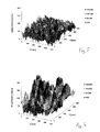
- the measurement results of the optical path difference for the two polarization directions, which are parallel to the main stress directions of the glass sheet, are shown above the coordinates X and Y of a measurement area of 50 cm x 50 cm.
- the optical path difference at no point of the measuring surface is more than 80 nm.
- Such a thermally toughened glass pane is therefore particularly suitable for use as architectural glass, in particular for large-area slices with an area of at least 1 m 2 or even more than 5 m 2 .
- FIG. 6 In comparison, the result of a measurement of the optical path difference over a measurement area having a size of 50 cm ⁇ 50 cm is shown in a thermally toughened glass pane according to the prior art.
- optical path differences of more than 150 nm occur, which, depending on the incidence of light, can lead to color deviations that are visible to a viewer of the pane.
Landscapes
- Physics & Mathematics (AREA)
- Chemical & Material Sciences (AREA)
- Thermal Sciences (AREA)
- Engineering & Computer Science (AREA)
- Materials Engineering (AREA)
- Organic Chemistry (AREA)
- General Physics & Mathematics (AREA)
- Mathematical Physics (AREA)
- Re-Forming, After-Treatment, Cutting And Transporting Of Glass Products (AREA)
Applications Claiming Priority (1)
| Application Number | Priority Date | Filing Date | Title |
|---|---|---|---|
| DE102008045416A DE102008045416A1 (de) | 2008-09-02 | 2008-09-02 | Vorrichtung und Verfahren zur Herstellung thermisch vorgespannter Glasscheiben und thermisch vorgespannte Glasscheibe |
Publications (2)
| Publication Number | Publication Date |
|---|---|
| EP2159199A2 true EP2159199A2 (fr) | 2010-03-03 |
| EP2159199A3 EP2159199A3 (fr) | 2015-05-20 |
Family
ID=41265624
Family Applications (1)
| Application Number | Title | Priority Date | Filing Date |
|---|---|---|---|
| EP20090167734 Withdrawn EP2159199A3 (fr) | 2008-09-02 | 2009-08-12 | Dispositif et procédé de fabrication de plaques de verre précontraintes thermiquement et plaque de verre précontrainte thermiquement |
Country Status (2)
| Country | Link |
|---|---|
| EP (1) | EP2159199A3 (fr) |
| DE (1) | DE102008045416A1 (fr) |
Cited By (2)
| Publication number | Priority date | Publication date | Assignee | Title |
|---|---|---|---|---|
| WO2013045512A2 (fr) | 2011-09-30 | 2013-04-04 | Arcon Flachglas-Veredlung Gmbh & Co. Kg | Système de couches pour verre de protection solaire, verre de protection solaire et procédé de fabrication d'un verre de protection solaire |
| CN118671030A (zh) * | 2024-08-22 | 2024-09-20 | 浙江祥都建筑科技有限公司 | 幕墙玻璃多性能检测装置 |
Families Citing this family (4)
| Publication number | Priority date | Publication date | Assignee | Title |
|---|---|---|---|---|
| AT511055B1 (de) * | 2011-03-24 | 2012-09-15 | Softsolution Gmbh | Vorrichtung zur projektion von produkt- bzw. produktionsrelevanten bild- und textdaten an anlagen zur produktion von einzel- bzw. isolierglasscheiben |
| AT515523B1 (de) * | 2014-04-07 | 2015-10-15 | Hans Höllwart Forschungszentrum Für Integrales Bauwesen Ag | Verfahren und Vorrichtung zur Charakterisierung von Spannungen in einem flächigen, transparenten Gegenstand |
| DE102018123284A1 (de) | 2018-09-21 | 2020-03-26 | sedak GmbH & Co. KG | Vorrichtung zum Tempern von Glasscheiben |
| US12596358B2 (en) | 2022-01-06 | 2026-04-07 | Cardinal Ig Company | Self-correcting edge quality in a glass tempering system |
Citations (3)
| Publication number | Priority date | Publication date | Assignee | Title |
|---|---|---|---|---|
| DE19511707A1 (de) | 1995-03-30 | 1996-10-02 | Laser Sorter Gmbh | Verfahren zur Bestimmung von Spannungen in transparenten Materialien |
| DE19720330C1 (de) | 1997-05-15 | 1998-11-12 | Sekurit Saint Gobain Deutsch | Verfahren und Vorrichtung zur Messung von Spannungen in Glasscheiben mit Hilfe des Streulichtverfahrens |
| EP1529761A1 (fr) | 2003-11-05 | 2005-05-11 | arcon II Flachglasveredelung GmbH & Co. KG | Empilement de couches à émissivité E faible à haute résistance thermique, son procédé de fabrication et son utilisation comme revêtement d'un substrat |
Family Cites Families (6)
| Publication number | Priority date | Publication date | Assignee | Title |
|---|---|---|---|---|
| BE786807A (fr) * | 1972-07-27 | 1972-11-16 | Lambert Jean Louis | Appareil de commande automatique pour la trempe thermique du verre. |
| GB2191998A (en) * | 1986-06-26 | 1987-12-31 | Pilkington Brothers Plc | Heat strengthened glass |
| US6180237B1 (en) * | 1997-06-13 | 2001-01-30 | Asahi Glass Company Ltd. | Tempered glass |
| JP3414205B2 (ja) * | 1997-06-27 | 2003-06-09 | 日本板硝子株式会社 | 合わせガラス |
| US20030076487A1 (en) * | 2001-08-03 | 2003-04-24 | Cannon Bret D. | System and method for glass processing and stress measurement |
| JP2004067416A (ja) * | 2002-08-02 | 2004-03-04 | Nippon Sheet Glass Co Ltd | ディスプレイ用前面ガラス板、そのガラス板の製造方法、および、製造装置 |
-
2008
- 2008-09-02 DE DE102008045416A patent/DE102008045416A1/de not_active Withdrawn
-
2009
- 2009-08-12 EP EP20090167734 patent/EP2159199A3/fr not_active Withdrawn
Patent Citations (3)
| Publication number | Priority date | Publication date | Assignee | Title |
|---|---|---|---|---|
| DE19511707A1 (de) | 1995-03-30 | 1996-10-02 | Laser Sorter Gmbh | Verfahren zur Bestimmung von Spannungen in transparenten Materialien |
| DE19720330C1 (de) | 1997-05-15 | 1998-11-12 | Sekurit Saint Gobain Deutsch | Verfahren und Vorrichtung zur Messung von Spannungen in Glasscheiben mit Hilfe des Streulichtverfahrens |
| EP1529761A1 (fr) | 2003-11-05 | 2005-05-11 | arcon II Flachglasveredelung GmbH & Co. KG | Empilement de couches à émissivité E faible à haute résistance thermique, son procédé de fabrication et son utilisation comme revêtement d'un substrat |
Cited By (2)
| Publication number | Priority date | Publication date | Assignee | Title |
|---|---|---|---|---|
| WO2013045512A2 (fr) | 2011-09-30 | 2013-04-04 | Arcon Flachglas-Veredlung Gmbh & Co. Kg | Système de couches pour verre de protection solaire, verre de protection solaire et procédé de fabrication d'un verre de protection solaire |
| CN118671030A (zh) * | 2024-08-22 | 2024-09-20 | 浙江祥都建筑科技有限公司 | 幕墙玻璃多性能检测装置 |
Also Published As
| Publication number | Publication date |
|---|---|
| DE102008045416A1 (de) | 2010-03-04 |
| EP2159199A3 (fr) | 2015-05-20 |
Similar Documents
| Publication | Publication Date | Title |
|---|---|---|
| DE102008054139B4 (de) | Glas- oder Glaskeramik-Substrat mit Kratzschutzbeschichtung, dessen Verwendung und Verfahren zu dessen Herstellung | |
| DE60005393T2 (de) | Wärmeabsorbierender filter und verfahren zu dessen herstellung | |
| EP2300389B1 (fr) | Produit de verre | |
| EP2798397B1 (fr) | Dispositif de régulation en fonction de la température du passage d'énergie à travers une surface transparente | |
| DE102012103076B4 (de) | Linsensystem für ein Kameramodul mit Infrarotfilter und Kameramodul mit einem Linsensystem sowie Verfahren zur Herstellung eines Linsensystems | |
| DE102008045416A1 (de) | Vorrichtung und Verfahren zur Herstellung thermisch vorgespannter Glasscheiben und thermisch vorgespannte Glasscheibe | |
| DE102007032371A1 (de) | Verfahren zum Beschichten eines optischen Bauelements für eine Laseranordnung | |
| EP2744763A1 (fr) | Procédé et dispositif de production d'un système de couches à faible émissivité | |
| CH713317B1 (de) | Substrat beschichtet mit einem Anti-Reflex-Beschichtungssystem mit Hartstoffbeschichtung sowie Verfahren zu dessen Herstellung. | |
| DE102020203750A1 (de) | Vorrichtung zur Erfassung einer Temperatur, Anlage zur Herstellung eines optischen Elementes und Verfahren zur Herstellung eines optischen Elementes | |
| WO2016206677A1 (fr) | Objectif ir à compensation thermique et caméra ir équipée d'un tel objectif ir | |
| EP2869963A1 (fr) | Dispositif et procédé d'usinage laser de substrats de grande surface au moyen d'au moins deux portiques | |
| EP3743393A1 (fr) | Verre protecteur solaire et son procédé de fabrication | |
| DE202017100512U1 (de) | Optische Filter und/oder Spiegel | |
| CH712550A2 (de) | Verfahren zur Herstellung eines optischen Elements. | |
| WO2013087358A1 (fr) | Vitrage atténuant la réflexion radar | |
| DE10019045B4 (de) | Verfahren zum Herstellen von Viellagensystemen | |
| EP3206999A1 (fr) | Procédé de fabrication d'un élément de façade en verre de protection contre la lumiere et élément de facade de protection contre la lumiere | |
| DE102013103282A1 (de) | Polarisatoranordnung zum räumlichen Trennen von Polarisationszuständen eines Lichtstrahlenbündels | |
| DE102013112990A1 (de) | Solar-Control-Schichtsystem mit intensivem Farbeindruck, Verfahren zu dessen Herstellung und Glaseinheit | |
| DE102010006133A1 (de) | Antireflexschichtsystem und Verfahren zu dessen Herstellung | |
| EP2180484B1 (fr) | Composant optique de rayonnement pour l'influence du rayonnement en fonction de son spectre de longueurs d'ondes | |
| EP1591750B1 (fr) | Procédé et appareil pour contrôler l'épaisseur d'une couche sur un ruban en mouvement dans sa direction longitudinale | |
| DE102023209929B3 (de) | Verfahren und Vorrichtung zur Überwachung von Beschichtungsprozessen | |
| EP3191819A1 (fr) | Ensemble de faisceaux de neutrons polarisés et procédé d'analyse de la polarisation |
Legal Events
| Date | Code | Title | Description |
|---|---|---|---|
| PUAI | Public reference made under article 153(3) epc to a published international application that has entered the european phase |
Free format text: ORIGINAL CODE: 0009012 |
|
| AK | Designated contracting states |
Kind code of ref document: A2 Designated state(s): AT BE BG CH CY CZ DE DK EE ES FI FR GB GR HR HU IE IS IT LI LT LU LV MC MK MT NL NO PL PT RO SE SI SK SM TR |
|
| AX | Request for extension of the european patent |
Extension state: AL BA RS |
|
| PUAL | Search report despatched |
Free format text: ORIGINAL CODE: 0009013 |
|
| AK | Designated contracting states |
Kind code of ref document: A3 Designated state(s): AT BE BG CH CY CZ DE DK EE ES FI FR GB GR HR HU IE IS IT LI LT LU LV MC MK MT NL NO PL PT RO SE SI SK SM TR |
|
| AX | Request for extension of the european patent |
Extension state: AL BA RS |
|
| RIC1 | Information provided on ipc code assigned before grant |
Ipc: C03B 27/04 20060101AFI20150410BHEP |
|
| STAA | Information on the status of an ep patent application or granted ep patent |
Free format text: STATUS: THE APPLICATION IS DEEMED TO BE WITHDRAWN |
|
| 18D | Application deemed to be withdrawn |
Effective date: 20151121 |