EP2159346A2 - Matelas de pose de carrelage - Google Patents
Matelas de pose de carrelage Download PDFInfo
- Publication number
- EP2159346A2 EP2159346A2 EP09168136A EP09168136A EP2159346A2 EP 2159346 A2 EP2159346 A2 EP 2159346A2 EP 09168136 A EP09168136 A EP 09168136A EP 09168136 A EP09168136 A EP 09168136A EP 2159346 A2 EP2159346 A2 EP 2159346A2
- Authority
- EP
- European Patent Office
- Prior art keywords
- tile
- layer
- laying mat
- tile laying
- moisture
- Prior art date
- Legal status (The legal status is an assumption and is not a legal conclusion. Google has not performed a legal analysis and makes no representation as to the accuracy of the status listed.)
- Withdrawn
Links
- 238000010521 absorption reaction Methods 0.000 claims abstract description 35
- 239000004033 plastic Substances 0.000 claims abstract description 22
- 229920003023 plastic Polymers 0.000 claims abstract description 22
- 229920000728 polyester Polymers 0.000 claims abstract description 5
- 238000004519 manufacturing process Methods 0.000 claims abstract description 4
- 239000000853 adhesive Substances 0.000 claims description 70
- 230000001070 adhesive effect Effects 0.000 claims description 70
- 239000004753 textile Substances 0.000 claims description 16
- 239000004744 fabric Substances 0.000 claims description 13
- 125000006850 spacer group Chemical group 0.000 claims description 8
- 238000002844 melting Methods 0.000 claims 1
- 230000008018 melting Effects 0.000 claims 1
- 239000002759 woven fabric Substances 0.000 abstract description 3
- 238000000034 method Methods 0.000 abstract description 2
- 239000010410 layer Substances 0.000 description 110
- 239000012790 adhesive layer Substances 0.000 description 21
- 239000000758 substrate Substances 0.000 description 19
- 239000004570 mortar (masonry) Substances 0.000 description 17
- 241000272165 Charadriidae Species 0.000 description 8
- 239000002131 composite material Substances 0.000 description 5
- 238000010276 construction Methods 0.000 description 4
- 239000000463 material Substances 0.000 description 4
- 239000000919 ceramic Substances 0.000 description 3
- 230000006835 compression Effects 0.000 description 3
- 238000007906 compression Methods 0.000 description 3
- 238000013016 damping Methods 0.000 description 3
- 238000001035 drying Methods 0.000 description 3
- 230000000694 effects Effects 0.000 description 3
- 238000009413 insulation Methods 0.000 description 3
- 238000006073 displacement reaction Methods 0.000 description 2
- 239000002184 metal Substances 0.000 description 2
- 230000000149 penetrating effect Effects 0.000 description 2
- 239000004952 Polyamide Substances 0.000 description 1
- 238000004026 adhesive bonding Methods 0.000 description 1
- 230000015572 biosynthetic process Effects 0.000 description 1
- 230000001427 coherent effect Effects 0.000 description 1
- 230000008878 coupling Effects 0.000 description 1
- 238000010168 coupling process Methods 0.000 description 1
- 238000005859 coupling reaction Methods 0.000 description 1
- 230000001419 dependent effect Effects 0.000 description 1
- 238000009826 distribution Methods 0.000 description 1
- 239000003292 glue Substances 0.000 description 1
- 230000001771 impaired effect Effects 0.000 description 1
- 229910052500 inorganic mineral Inorganic materials 0.000 description 1
- 239000011229 interlayer Substances 0.000 description 1
- 239000007788 liquid Substances 0.000 description 1
- 230000007774 longterm Effects 0.000 description 1
- 238000010309 melting process Methods 0.000 description 1
- 239000011707 mineral Substances 0.000 description 1
- 238000000465 moulding Methods 0.000 description 1
- 239000005445 natural material Substances 0.000 description 1
- 239000004745 nonwoven fabric Substances 0.000 description 1
- 230000035515 penetration Effects 0.000 description 1
- 229920002647 polyamide Polymers 0.000 description 1
- 238000003825 pressing Methods 0.000 description 1
- 230000000630 rising effect Effects 0.000 description 1
- 238000010008 shearing Methods 0.000 description 1
- 239000007787 solid Substances 0.000 description 1
- 239000004575 stone Substances 0.000 description 1
- 229920001187 thermosetting polymer Polymers 0.000 description 1
- XLYOFNOQVPJJNP-UHFFFAOYSA-N water Substances O XLYOFNOQVPJJNP-UHFFFAOYSA-N 0.000 description 1
- 239000002023 wood Substances 0.000 description 1
Images
Classifications
-
- E—FIXED CONSTRUCTIONS
- E04—BUILDING
- E04F—FINISHING WORK ON BUILDINGS, e.g. STAIRS, FLOORS
- E04F15/00—Flooring
- E04F15/18—Separately-laid insulating layers; Other additional insulating measures; Floating floors
- E04F15/182—Underlayers coated with adhesive or mortar to receive the flooring
-
- E—FIXED CONSTRUCTIONS
- E04—BUILDING
- E04F—FINISHING WORK ON BUILDINGS, e.g. STAIRS, FLOORS
- E04F15/00—Flooring
- E04F15/18—Separately-laid insulating layers; Other additional insulating measures; Floating floors
- E04F15/185—Underlayers in the form of studded or ribbed plates
-
- E—FIXED CONSTRUCTIONS
- E04—BUILDING
- E04F—FINISHING WORK ON BUILDINGS, e.g. STAIRS, FLOORS
- E04F15/00—Flooring
- E04F15/18—Separately-laid insulating layers; Other additional insulating measures; Floating floors
- E04F15/186—Underlayers covered with a mesh or the like
-
- E—FIXED CONSTRUCTIONS
- E04—BUILDING
- E04F—FINISHING WORK ON BUILDINGS, e.g. STAIRS, FLOORS
- E04F15/00—Flooring
- E04F15/18—Separately-laid insulating layers; Other additional insulating measures; Floating floors
- E04F15/20—Separately-laid insulating layers; Other additional insulating measures; Floating floors for sound insulation
- E04F15/203—Separately-laid layers for sound insulation
-
- Y—GENERAL TAGGING OF NEW TECHNOLOGICAL DEVELOPMENTS; GENERAL TAGGING OF CROSS-SECTIONAL TECHNOLOGIES SPANNING OVER SEVERAL SECTIONS OF THE IPC; TECHNICAL SUBJECTS COVERED BY FORMER USPC CROSS-REFERENCE ART COLLECTIONS [XRACs] AND DIGESTS
- Y10—TECHNICAL SUBJECTS COVERED BY FORMER USPC
- Y10T—TECHNICAL SUBJECTS COVERED BY FORMER US CLASSIFICATION
- Y10T428/00—Stock material or miscellaneous articles
- Y10T428/24—Structurally defined web or sheet [e.g., overall dimension, etc.]
- Y10T428/24479—Structurally defined web or sheet [e.g., overall dimension, etc.] including variation in thickness
Definitions
- the present invention relates to a tile laying mat for laying tiles on a substrate.
- tiles is used below as a generic term for all hard coverings made of ceramic, natural stone or mineral bonded tiles and slabs as well as made of plastics or wood-based materials rigid lining material.
- the DE 37 01 414 A1 a tile laying mat with a plastic plate having a profile consisting of mutually parallel, alternating dovetailed webs and dovetailed grooves, and with a connected to the underside of the plastic plate attachment layer for securing the tile laying mat on a substrate, wherein the attachment layer is formed by a coarse-meshed nonwoven fabric ,
- the wall or floor surface to be covered with tiles is first coated with an adhesive or mortar layer. Then the tile laying mat is glued to the substrate with the aid of the coarse-mesh net fleece arranged on its underside.
- the directed to the ground side dovetailed grooves of the plastic plate which are only partially filled with adhesive or mortar, form pressure equalization spaces that compensate in the finished floor joint between the substrate and the tiles occurring stresses and serve to dissipate moisture from the substrate or the adhesive - or mortar layer rises to tile laying mat.
- another adhesive or mortar layer is applied to the top of the plastic plate, wherein the adhesive or the mortar clamped in the open to the upper side of the plastic plate dovetailed grooves. In this way, a firm hold in the dried state of the adhesive or mortar generated between the plastic plate and the adhesive or mortar layer. After applying the adhesive or mortar layer tiles can now be laid on top of the tile laying mat.
- a tile laying mat which has both a decoupling and a drainage function.
- a major disadvantage of this tile laying mat is that although rising from below towards the tile laying mat moisture can be collected and removed in the pressure compensation chambers formed by the dovetailed grooves of the plastic plate directed to the ground side, but not moisture in the adhesive or mortar layer between the Tile laying mat and the tiles is present. This is particularly a problem when very large, moisture-impermeable tiles are used, so that a removal of moisture through the existing joints between the tiles is not sufficient. Accordingly, the adhesive between the tile laying mat and the tiles can not dry sufficiently, which may lead to the tiles peeling off, depending on the type of glue used or the temperature variations experienced by the composite.
- tile laying mat is in the EP 1 712 695 A2 disclosed.
- This tile laying mat comprises a film-like plastic plate with respect to its top outstanding, load-bearing, hollow towards the bottom, arranged in a uniform surface distribution, partially undercut support elements, between the support elements open wasserabracede channels are formed.
- a water- and vapor-permeable non-woven or fabric-like cover is arranged on the support elements.
- the laying mat is embedded on the substrate over its entire surface in the area of its lower bearing surfaces in a still soft, thermosetting Dünnbettmörtel für, with the mortar anchored in the undercuts of the undercut trained support elements, creating a solid bond between the ground and the tile laying mat is produced.
- the ceramic plates are laid directly on a thin-bed mortar layer on the top of the tile laying mat arranged fleece-like cover and fixed, where the mortar is clamped to the fleece, so that the tiles are securely held on the tile laying mat.
- moisture present in the thin-bed mortar layer disposed between the tile-laying mat and the tiles can pass through the non-woven or fabric-like cover into the drainage channels and be discharged therefrom.
- moisture coming from below can not penetrate the film-like plastic plate, which is why removal of moisture from the substrate or from the thin-bed mortar layer arranged underneath the tile-laying mat is not possible.
- a tile laying mat of alternative construction is to be provided which allows two-sided removal of moisture even when using large-area, moisture-impermeable tiles.
- the tile laying mat according to the present invention is a moisture-permeable mat, that is to say a mat which, when installed as intended, allows water in the liquid and / or vapor state to be passed both from above and from below.
- a moisture-receiving layer having a thickness of at least 1 mm to ensure a sufficient moisture-absorbing volume.
- This moisture absorption layer is preferably not only moisture-permeable but also moisture-wicking and / or moisture-balancing. Accordingly, the moisture absorbed in it is evenly distributed and / or derived.
- the moisture absorption layer is preferably air-permeable and / or heat-insulating and / or sound-insulating.
- the moisture-absorbing layer also has a plurality of recesses extending from the upper side toward the lower side. These recesses, which are preferably distributed evenly over the entire surface of the tile laying mat are filled in the laying of the tiles with adhesive or mortar, whereby Tragstelzen are formed, which absorb those forces and forward to the ground, which are applied to the tiles.
- These support stilts also prevent the moisture absorption volume provided by the moisture-receiving layer from being reduced due to forces acting on the tiles. So they serve as spacers, which counteract a compression of the moisture absorption layer and accordingly ensure the proper moisture absorption function of the tile laying mat.
- the tile laying mat is to perform a decoupling function in addition to its moisture absorption function, then it is important that the recesses do not penetrate the underside of the tile laying mat.
- the recesses must therefore not form through holes. Accordingly, it is prevented that the supporting stilts formed by the recesses connect with the adhesive or mortar layer arranged below the tile laying mat and a direct coupling is produced.
- the load-bearing stilts can move within the recesses-possibly with displacement of adjacently arranged regions of the moisture absorption layer.
- the bottom and / or side walls of the recesses are advantageously at least partially formed such that there is no adhesive bond between them and a tile adhesive introduced into the recesses or the load-bearing stilts.
- the bottom and / or side walls of the recesses are in the form of a smooth plastic surface which forms an adhesive bond between the bottom and / or side walls of the recesses and the tile adhesive prevented.
- the moisture absorption layer is advantageously non-woven or fabric-like and has a corresponding elasticity. It preferably comprises the same or differently formed plastic threads, in particular polyester threads, which can be arranged regularly with a predetermined orientation and / or in the form of a fabric or irregularly as a tangle.
- the moisture absorption layer is preferably a fastening layer connected, in particular glued.
- the underside or upper side of the attachment layer is preferably designed such that it forms an adhesive bond with a tile adhesive.
- the attachment layer may be formed for this purpose a fleece, tissue or lattice-like. In this case, the attachment layer should prevent too deep penetration of the adhesive into the moisture absorption layer in order not to impair the function of the moisture absorption layer.
- the moisture-receiving layer is, in accordance with an embodiment of the present invention, a pile fabric layer of a spacer fabric disposed between a lower and an upper cover fabric layer.
- spacer fabrics are already known in the prior art in other contexts and are used in particular for the upholstery of objects, such as bicycle helmets, shoe soles or the like. They are mainly made of polyamides and polyester and offer a very good heat and moisture regulation due to the existing between the threads of such a knit cavities. These spacer fabrics can be produced in different thicknesses. For the present application, spacer fabrics having a thickness of 1 mm and more are preferred.
- the defined distance between the two cover textile layers of the spacer knitted fabric is normally achieved by the pressure-elastic threads (pile threads).
- the use of such spacer fabric as a carrier for ceramic plates thus ensures both a good drainage and thermal insulation function. Further, if desired, a decoupling function can be realized.
- the underside of the lower cover textile layer and / or the upper side of the upper cover textile layer is / are, according to one embodiment of the present invention, non-woven in order to achieve a good adhesive bond between the underside of the lower cover textile layer and an adhesive.
- a bonding layer in particular glued, the underside / top or the outwardly facing side is formed such that it with a tile adhesive an adhesive bond for fixing the tile laying mat is received.
- the outwardly facing side of the attachment layer is advantageously formed like a fleece to achieve the desired adhesive bond.
- the tile laying mat has a total thickness preferably in the range of 1-5 mm. Furthermore, it is advantageously designed so flexible that it can be rolled up. Of course, it can also have a greater thickness, for example, if a good air circulation in the attachment of tiles to wall or ceiling surfaces to be guaranteed.
- the tile laying mat is designed so tear-resistant that it can be fastened to walls and ceilings with fastening means, in particular with dowels and screws.
- the present invention provides a method for producing a tile laying mat of the type defined above.
- the method includes the step of forming the recesses of the moisture-receiving layer by partially fusing at least the moisture-receiving layer, thereby producing smooth bottom and / or side walls that prevent adhesive bonding to a tile adhesive.
- the recesses are advantageously formed using hot stamping dies of a molding tool in the tile laying mat.
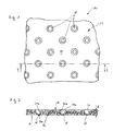
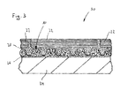
- FIGS. 1 to 3 show a tile laying mat 10 according to a first embodiment of the present invention, wherein the Figures 1 and 2 the tile laying mat 10 show itself, whereas the FIG. 3 in the Figures 1 and 2 illustrated tile laying mat 10 in the installed state represents.
- the tile laying mat 10 which may be plate, sheet or carpet-like, comprises a moisture-permeable, fleece-like moisture absorption layer 12.
- the moisture absorption layer 12 has a plurality of irregularly arranged in the manner of a tangle plastic threads, such as polyester threads, which are at least partially interconnected and Accordingly, create a coherent mat-like composite with a top 14 and a bottom 16.
- the moisture absorption layer also includes a plurality of recesses 18 extending from the top 14 towards the bottom 16, but not piercing the latter.
- the recesses 18 have a circular cross-section, which tapers conically from top to bottom, whereby upside-down truncated cone shapes are formed.
- These recesses 18 are made by pressing hot punches of a die, the ends of which have a negative contour corresponding to the contours of the recesses 18, into the top 14 of the moisture-receiving layer 12, the plastic threads contacting the punches due to the high temperature come to be melted, so that the recesses 18 arise. Due to the melting process of the plastic threads, the recesses 18 receive a smooth bottom wall 20a and a smooth side wall 20b.
- the thickness d of the moisture absorption layer 12 or the tile laying mat 10 is in the present case 3 mm. In principle, however, the thickness can be in a range between 1 and 5 mm. If, for example, a floor structure with a low height is in the foreground, then a small thickness d is recommended. If, on the other hand, a good insulation function is of particular importance, it is advisable to choose a larger thickness d.
- tile adhesive layer 26 For laying tiles 22 on a substrate 24, which may be a floor or a wall surface, is on the substrate 24, as in FIG. 3 is shown, first applied a tile adhesive layer 26. Subsequently, the tile laying mat 10 is pressed onto the tile adhesive layer 26 with the underside 16 of the moisture receiving layer 12, tile adhesive partially penetrating the interstices between the plastic threads of the moisture receiving layer 12 and enclosing the plastic threads, so that the moisture receiving layer 12 over the tile adhesive layer after drying of the adhesive 26 is firmly connected to the substrate 24. Subsequently, a further tile adhesive layer 28 is applied to the upper side 14 of the moisture absorption layer 12.
- the tile adhesive penetrates partially into the nonwoven on the upper side 14 of the moisture absorption layer 12, whereby after drying of the tile adhesive also a firm bond between the tile adhesive layer 28 and the moisture absorption layer is generated. Further the tile adhesive 28 applied to the upper side 14 of the moisture-receiving layer 12 penetrates into the recesses 18 and fills them completely. Due to the smooth bottom and side walls 20a, 20b of the recesses 18, however, unlike the top 14, no strong bond is created between the tile adhesive and the walls 20a, 20b of the recesses 18. In a subsequent step, the tiles 22 can now be placed on the tile adhesive layer 28, in order in this way the in FIG. 3 finished floor composite 30 completed.
- the moisture-receiving layer 12 of the tile-laying mat 10 is moisture-permeable, moisture present in the substrate 24 and in the lower tile adhesive layer 28 may enter the moisture-receiving layer 12 through the upper surface 16 as well as moisture present in the upper tile adhesive layer 28 , Accordingly, the substrate 24 as well as the tile adhesive layers 26 and 28 can easily completely dry out and harden, whereby the extracted moisture is collected in the moisture absorption layer 12 and possibly removed by it.
- the penetrating from above into the recesses 18 adhesive forms supporting stilts, which extend from the top 14 of the moisture receiving layer 12 in the direction of the bottom 16, the latter, however, do not break, with the support stilts compressing the underlying them fleece of the moisture absorption layer 12 against the ground Support 24 or tile adhesive 26. Accordingly, there is no direct connection between the upper adhesive layer 28 and the lower adhesive layer 26, so that the adhesive layers 26, 28 are decoupled from each other and thus the substrate 24 from the tiles 22. Due to the smooth bottom and side walls 20a, 20b of the recesses 18, the support stilts are also loosely received in the recesses 18, so they can move laterally with displacement of the adjacently arranged nonwoven moisture absorption layer 12. In this way, existing stresses between the substrate 24 and the tiles 22 can be compensated for and a loosening of the tiles 22 due to such stresses can be prevented.
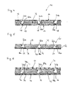
- FIG. 4 shows a cross-sectional view of a tile laying mat 40 according to a second embodiment of the present invention.
- the tile laying mat 40 comprises a moisture absorption layer 42 which is formed of plastic threads arranged transversely to each other.
- the moisture-receiving layer 42 comprises a regular, brush-like structure, which has a relatively high strength due to the orientation of the plastic threads. Accordingly, the moisture-receiving layer 42 is less likely to compress than, for example, the moisture-receiving layer 12 of FIG FIGS. 1 to 3
- the tile laying mat 40 further comprises two attachment layers 44 and 46 of nonwoven, which receive the moisture absorbing layer 42 between them and are each glued to this.
- the tile laying mat 40 further comprises analogous to FIG. 1 a plurality of recesses 48 each extending through the upper attachment layer 46 and the moisture-receiving layer 42. On the other hand, the recesses 48 do not pass through the lower attachment layer 44.
- the recesses 48 are analogous to FIG. 1 regularly distributed over the entire top of the tile laying mat 40 and have a circular cross-section gradually tapers from the upper attachment layer 46 in the direction of the lower attachment layer 46, as in FIG. 4 can be seen.
- the recesses 48 of the tile laying mat 40 smooth bottom walls 50a and smooth side walls 50b, whereby an adhesive bond between the walls 50a, 50b of the recesses 48 and a disposed in the recesses 48 tile adhesive is prevented.
- Tiles 22 on a substrate 24 below Use of the tile laying mat 40 are laid, where initially a tile adhesive layer 26 is applied to the substrate 24 again. Thereafter, the tile laying mat with the lower attachment layer 44 is pressed onto the tile adhesive layer 26, so that the tile adhesive at least partially penetrates into the fleece of the attachment layer 44 and surrounds it, so that in the cured state of the tile adhesive, a firm bond between the tile adhesive layer 26 and the attachment layer 44th is produced. Subsequently, a further tile adhesive layer 28 is applied to the top of the upper attachment layer 46 of the tile laying mat 40, wherein the tile adhesive partially penetrates into the web of the upper attachment layer 46 so that a correspondingly strong bond is also generated there.
- the tile adhesive penetrates into the recesses 48 of the tile laying mat 40 and fills them completely. Due to the smooth bottom and side walls 50a, 50b of the recesses 48, however, an adhesive bond between tile adhesive and the bottom and side walls 50a, 50b of the recesses 48 is prevented.
- FIG. 5 shows a cross-sectional view of a tile laying mat 60 according to a third embodiment of the present invention.
- the tile laying mat 60 includes a moisture-receiving layer 42 as previously described with reference to FIG FIG. 4 has been described.
- an intermediate layer 62 is further adhesively held.
- this intermediate layer is a moisture-permeable woven fabric layer which does not adhere to adhesive bond with tile adhesive when it comes into contact with it.
- a fastening layer 44 is fixed, as previously described with reference to the second embodiment.
- the tile laying mat 60 comprises a multiplicity of regularly distributed recesses 64 in an analogous manner FIG.
- These recesses 64 extend through the entire moisture absorption layer 42 and comprise a circular cross section which widens in the direction of the underside 16, starting from the upper side 14 of the moisture absorption layer 42, so that arise truncated cone shapes. Alternatively, for example, a truncated pyramidal formation or the like would be conceivable here as well.
- the recesses 64 viewed from above, form undercuts in which tile adhesives introduced into the recesses 64 can be clamped. Thus, on the in FIG. 4 omitted upper attachment layer can be omitted.
- the recesses 64 also have smooth bottom and side walls 66a, 66b which, together with the intermediate layer 62, prevent sticking of tile adhesive within the recesses 64.
- FIG. 6 shows a cross-sectional view of a tile laying mat 70 according to a fourth embodiment of the present invention.
- the tile laying mat 70 includes a moisture-receiving layer 42 as previously described with reference to FIG FIG. 4 has been described.
- a woven upper cover textile layer 72 and a woven lower cover textile layer 74 are fixedly bonded to the upper surface 14 and the lower surface 16 of the moisture receiving layer 42, so that the moisture absorption layer 42 is sandwiched between the cover textile layers 72 and 74 in a knit-knitted manner to form a so-called pile layer.
- the tile laying mat 70 further includes a plurality of recesses 66 analogous to FIG. 1 extending through the upper cover textile layer 72 and the moisture-receiving layer 42.
- the recesses 76 are cylindrically shaped and comprise smooth bottom and side walls 78a, 78b, which do not form an adhesive bond with tile adhesive. Also, the woven fabric cover layers 72 and 74 do not bond with tile adhesive. For this reason, a fastening layer 44 is attached to the lower cover layer 74, as described with reference to FIG FIG. 4 has already been explained in order to be able to stick the tile laying mat 70 to a substrate using a tile adhesive. Further, a mounting grid is glued to the upper decktextil slaughter 72, the mesh width is so large that applied to the tile laying mat 70 tile adhesive easily penetrate the mounting grid 80 and fill the recesses 76. This mounting grid 80 provides a firm adhesive bond between the Tile adhesive and the top of the tile laying mat 70 in order to produce in this way a proper floor joint can.
- the moisture-absorbing layers 12 and 42 of the tile-laying mats 10, 40, 60 and 70 of the embodiments described above are not only moisture-permeable but also moisture-wicking and moisture-compensating. In addition, they are permeable to air, heat-insulating and soundproofing.
- the moisture-receiving layers of the individual tile-laying mats may include not only plastic threads but also natural-material threads, metal threads, metal-sheathed metal threads, or the like. Also, combinations of filaments of different shapes and materials, such as open-cell foamed material, are possible. In addition, the recesses may have any cross-sectional shapes, such as polygonal, round or oval cross sections. Furthermore, the rigidity of the tile laying mat according to the invention in thickness direction is preferably selected such that the tile laying mat can at least absorb the weight of the adhesive layer arranged above it and the tiles, without any significant compression in Thickness direction to learn.
- the cavity provided by the moisture-receiving layer for absorbing moisture is prevented from being reduced during the drying of the adhesive due to the self-weight of the adhesive layer and the tiles.
- the support stilts prevent compression of the moisture-receiving layer.
- adheresive is meant all for the attachment of the tile laying mat and / or the attachment of the respective designated as tiles hard coverings suitable adhesives or mortars.
Landscapes
- Engineering & Computer Science (AREA)
- Architecture (AREA)
- Civil Engineering (AREA)
- Structural Engineering (AREA)
- Floor Finish (AREA)
- Road Paving Structures (AREA)
- Building Environments (AREA)
Applications Claiming Priority (1)
| Application Number | Priority Date | Filing Date | Title |
|---|---|---|---|
| DE102008045122A DE102008045122A1 (de) | 2008-09-01 | 2008-09-01 | Fliesenverlegematte |
Publications (2)
| Publication Number | Publication Date |
|---|---|
| EP2159346A2 true EP2159346A2 (fr) | 2010-03-03 |
| EP2159346A3 EP2159346A3 (fr) | 2012-12-12 |
Family
ID=41445588
Family Applications (1)
| Application Number | Title | Priority Date | Filing Date |
|---|---|---|---|
| EP09168136A Withdrawn EP2159346A3 (fr) | 2008-09-01 | 2009-08-19 | Matelas de pose de carrelage |
Country Status (4)
| Country | Link |
|---|---|
| US (1) | US20100055405A1 (fr) |
| EP (1) | EP2159346A3 (fr) |
| CA (1) | CA2676939A1 (fr) |
| DE (1) | DE102008045122A1 (fr) |
Cited By (2)
| Publication number | Priority date | Publication date | Assignee | Title |
|---|---|---|---|---|
| EP2754774A1 (fr) * | 2013-01-15 | 2014-07-16 | Sandro Thronicke | Couche intermédiaire pour une construction de revêtement |
| EP2749712A3 (fr) * | 2012-12-28 | 2015-01-28 | Walter Gutjahr | Sous-couche découplante |
Families Citing this family (7)
| Publication number | Priority date | Publication date | Assignee | Title |
|---|---|---|---|---|
| DE202006015397U1 (de) * | 2006-10-04 | 2006-12-07 | Blanke Gmbh & Co. Kg | Mehrschichtiges Aufbausystem für Bodenbeläge bei Fußbodenheizungen |
| DE202011051559U1 (de) * | 2011-10-06 | 2011-11-17 | Saniku S.A. | Entkopplungsbahn |
| DE102012203894A1 (de) | 2012-03-13 | 2013-09-19 | Henkel Ag & Co. Kgaa | Baubereichsbahn |
| DE102012112698A1 (de) | 2012-12-20 | 2014-06-26 | Sandro Thronicke | Entkopplungsmatte |
| US20150068838A1 (en) * | 2013-09-11 | 2015-03-12 | Keene Building Products Co., Inc. | Noise control device |
| JP2015212502A (ja) * | 2014-05-07 | 2015-11-26 | 株式会社大林組 | 床構造、及び、床構造の施工方法 |
| CA2945924C (fr) * | 2015-10-19 | 2023-03-21 | Keene Building Products Co., Inc. | Dispositif de jauge de lit de mortier, systeme et methode |
Citations (2)
| Publication number | Priority date | Publication date | Assignee | Title |
|---|---|---|---|---|
| DE3701414A1 (de) | 1987-01-20 | 1988-07-28 | Werner Schlueter | Verfahren und vorrichtung zum aufbringen von verkleidungen, wie keramikplattenbelaegen, putzmoertel oder dergleichen auf einem wand- oder einem bodenuntergrund eines gebaeudes |
| EP1712695A2 (fr) | 2005-04-13 | 2006-10-18 | Schlüter Systems KG | Construction d'un sol couvert avec carreaux de céramique |
Family Cites Families (6)
| Publication number | Priority date | Publication date | Assignee | Title |
|---|---|---|---|---|
| DE20317248U1 (de) * | 2003-11-06 | 2004-02-12 | Blanke & Co. | Mehrschichtiges Entkopplungs- und Abdichtungssystem |
| US7488523B1 (en) * | 2004-02-23 | 2009-02-10 | Polyguard Products, Inc. | Stress-relieving barrier membrane for concrete slabs and foundation walls |
| US7651757B2 (en) * | 2005-08-31 | 2010-01-26 | Sealed Air Corporation (Us) | Floor underlayment |
| DE102006033803A1 (de) * | 2006-03-06 | 2007-09-13 | Ewald Dörken Ag | Bahn, insbesondere zur Verwendung im Baubereich |
| JP5123511B2 (ja) * | 2006-06-23 | 2013-01-23 | ユニ・チャーム株式会社 | 不織布 |
| DE202008007390U1 (de) * | 2008-06-03 | 2008-08-14 | Weller, Jürgen | Schichtverbund als Träger für keramische, Stein- oder ähnliche Beläge |
-
2008
- 2008-09-01 DE DE102008045122A patent/DE102008045122A1/de not_active Withdrawn
-
2009
- 2009-08-19 EP EP09168136A patent/EP2159346A3/fr not_active Withdrawn
- 2009-08-28 CA CA002676939A patent/CA2676939A1/fr not_active Abandoned
- 2009-08-31 US US12/584,124 patent/US20100055405A1/en not_active Abandoned
Patent Citations (2)
| Publication number | Priority date | Publication date | Assignee | Title |
|---|---|---|---|---|
| DE3701414A1 (de) | 1987-01-20 | 1988-07-28 | Werner Schlueter | Verfahren und vorrichtung zum aufbringen von verkleidungen, wie keramikplattenbelaegen, putzmoertel oder dergleichen auf einem wand- oder einem bodenuntergrund eines gebaeudes |
| EP1712695A2 (fr) | 2005-04-13 | 2006-10-18 | Schlüter Systems KG | Construction d'un sol couvert avec carreaux de céramique |
Cited By (2)
| Publication number | Priority date | Publication date | Assignee | Title |
|---|---|---|---|---|
| EP2749712A3 (fr) * | 2012-12-28 | 2015-01-28 | Walter Gutjahr | Sous-couche découplante |
| EP2754774A1 (fr) * | 2013-01-15 | 2014-07-16 | Sandro Thronicke | Couche intermédiaire pour une construction de revêtement |
Also Published As
| Publication number | Publication date |
|---|---|
| US20100055405A1 (en) | 2010-03-04 |
| DE102008045122A1 (de) | 2010-03-04 |
| CA2676939A1 (fr) | 2010-03-01 |
| EP2159346A3 (fr) | 2012-12-12 |
Similar Documents
| Publication | Publication Date | Title |
|---|---|---|
| EP2159346A2 (fr) | Matelas de pose de carrelage | |
| EP2372041B1 (fr) | Plaque de support et leur procédé de fabrication | |
| EP3128103B1 (fr) | Tapis de desolidarisation | |
| EP1700970A2 (fr) | Plaque de support du type feuille de plastique | |
| EP1704290B1 (fr) | Plaque destinee a etre utilisee dans un systeme de pose, en particulier pour produire un revetement pour le sol et procede pour la produire | |
| EP2213811A2 (fr) | Structures multicouches en tant que support pour revêtements en céramique, en pierre ou analogue | |
| EP1088945B1 (fr) | Elément d'isolation d'une façade | |
| AT511765B1 (de) | Verfahren zum verbinden von mauersteinen | |
| EP2239024B1 (fr) | Revêtement de sol absorbant les chocs, notamment pour terrains de jeu ou installations de sport | |
| DE3932951A1 (de) | Fliesentafel, sowie verfahren zu deren herstellung | |
| EP1375780A1 (fr) | Matériau en matière plastique en forme de feuille ou plaque pour supporter des dalles ou carrelages | |
| EP1846630A1 (fr) | Element de voie de drainage ou de dallage pour la pose sur couche mince de dalles pour l'assechement ou la ventilation | |
| EP2625338B1 (fr) | Procédé de moussage d'une couche de mousse plastique | |
| EP2275624A1 (fr) | Isolation phonique | |
| DE202008007390U1 (de) | Schichtverbund als Träger für keramische, Stein- oder ähnliche Beläge | |
| EP0411653B1 (fr) | Plancher pour salle de sport | |
| DE102004011610A1 (de) | Verfahren zur Herstellung eines Verbundsystems zwischen Beton und einem hochpolymeren elastischen Material sowie ein nach diesem Verfahren hergestelltes Verbindungsmittel und dessen Verwendung | |
| EP2935723B1 (fr) | Matelas d'isolation pour revêtments de sol | |
| DE202012103656U1 (de) | Entkopplungsbahn | |
| AT13346U1 (de) | Vorrichtung mit Schichtverbund für die Montage einer Sanitäreinrichtung und Sanitäreinrichtung mit einem Schichtverbund | |
| DE3925742C2 (de) | Sporthallenboden | |
| DE4002601C2 (de) | Vorgefertigtes, transportierbares, selbsttragendes Bauelement, wie Platte, Wand oder Formteil | |
| EP1362965B1 (fr) | Matériau de construction | |
| EP2775037A1 (fr) | Tapis de désolidarisation pour une structure de revêtement de surface pouvant être recouverte d'éléments de revêtement | |
| EP3771554B1 (fr) | Corps en forme de plaque |
Legal Events
| Date | Code | Title | Description |
|---|---|---|---|
| PUAI | Public reference made under article 153(3) epc to a published international application that has entered the european phase |
Free format text: ORIGINAL CODE: 0009012 |
|
| AK | Designated contracting states |
Kind code of ref document: A2 Designated state(s): AT BE BG CH CY CZ DE DK EE ES FI FR GB GR HR HU IE IS IT LI LT LU LV MC MK MT NL NO PL PT RO SE SI SK SM TR |
|
| PUAL | Search report despatched |
Free format text: ORIGINAL CODE: 0009013 |
|
| AK | Designated contracting states |
Kind code of ref document: A3 Designated state(s): AT BE BG CH CY CZ DE DK EE ES FI FR GB GR HR HU IE IS IT LI LT LU LV MC MK MT NL NO PL PT RO SE SI SK SM TR |
|
| AX | Request for extension of the european patent |
Extension state: AL BA RS |
|
| RIC1 | Information provided on ipc code assigned before grant |
Ipc: E04F 15/20 20060101AFI20121108BHEP Ipc: E04F 15/18 20060101ALI20121108BHEP |
|
| 17P | Request for examination filed |
Effective date: 20130429 |
|
| STAA | Information on the status of an ep patent application or granted ep patent |
Free format text: STATUS: THE APPLICATION IS DEEMED TO BE WITHDRAWN |
|
| 18D | Application deemed to be withdrawn |
Effective date: 20150303 |