EP2159366A2 - Method and device for producing a square spacer frame for insulating glass panes - Google Patents
Method and device for producing a square spacer frame for insulating glass panes Download PDFInfo
- Publication number
- EP2159366A2 EP2159366A2 EP09010716A EP09010716A EP2159366A2 EP 2159366 A2 EP2159366 A2 EP 2159366A2 EP 09010716 A EP09010716 A EP 09010716A EP 09010716 A EP09010716 A EP 09010716A EP 2159366 A2 EP2159366 A2 EP 2159366A2
- Authority
- EP
- European Patent Office
- Prior art keywords
- frame
- corner
- frame legs
- legs
- leg
- Prior art date
- Legal status (The legal status is an assumption and is not a legal conclusion. Google has not performed a legal analysis and makes no representation as to the accuracy of the status listed.)
- Granted
Links
Images




Classifications
-
- E—FIXED CONSTRUCTIONS
- E06—DOORS, WINDOWS, SHUTTERS, OR ROLLER BLINDS IN GENERAL; LADDERS
- E06B—FIXED OR MOVABLE CLOSURES FOR OPENINGS IN BUILDINGS, VEHICLES, FENCES OR LIKE ENCLOSURES IN GENERAL, e.g. DOORS, WINDOWS, BLINDS, GATES
- E06B3/00—Window sashes, door leaves, or like elements for closing wall or like openings; Layout of fixed or moving closures, e.g. windows in wall or like openings; Features of rigidly-mounted outer frames relating to the mounting of wing frames
- E06B3/66—Units comprising two or more parallel glass or like panes permanently secured together
- E06B3/673—Assembling the units
- E06B3/67304—Preparing rigid spacer members before assembly
- E06B3/67308—Making spacer frames, e.g. by bending or assembling straight sections
-
- B—PERFORMING OPERATIONS; TRANSPORTING
- B29—WORKING OF PLASTICS; WORKING OF SUBSTANCES IN A PLASTIC STATE IN GENERAL
- B29C—SHAPING OR JOINING OF PLASTICS; SHAPING OF MATERIAL IN A PLASTIC STATE, NOT OTHERWISE PROVIDED FOR; AFTER-TREATMENT OF THE SHAPED PRODUCTS, e.g. REPAIRING
- B29C65/00—Joining or sealing of preformed parts, e.g. welding of plastics materials; Apparatus therefor
- B29C65/02—Joining or sealing of preformed parts, e.g. welding of plastics materials; Apparatus therefor by heating, with or without pressure
- B29C65/08—Joining or sealing of preformed parts, e.g. welding of plastics materials; Apparatus therefor by heating, with or without pressure using ultrasonic vibrations
-
- B—PERFORMING OPERATIONS; TRANSPORTING
- B29—WORKING OF PLASTICS; WORKING OF SUBSTANCES IN A PLASTIC STATE IN GENERAL
- B29C—SHAPING OR JOINING OF PLASTICS; SHAPING OF MATERIAL IN A PLASTIC STATE, NOT OTHERWISE PROVIDED FOR; AFTER-TREATMENT OF THE SHAPED PRODUCTS, e.g. REPAIRING
- B29C65/00—Joining or sealing of preformed parts, e.g. welding of plastics materials; Apparatus therefor
- B29C65/02—Joining or sealing of preformed parts, e.g. welding of plastics materials; Apparatus therefor by heating, with or without pressure
- B29C65/08—Joining or sealing of preformed parts, e.g. welding of plastics materials; Apparatus therefor by heating, with or without pressure using ultrasonic vibrations
- B29C65/081—Joining or sealing of preformed parts, e.g. welding of plastics materials; Apparatus therefor by heating, with or without pressure using ultrasonic vibrations having a component of vibration not perpendicular to the welding surface
-
- B—PERFORMING OPERATIONS; TRANSPORTING
- B29—WORKING OF PLASTICS; WORKING OF SUBSTANCES IN A PLASTIC STATE IN GENERAL
- B29C—SHAPING OR JOINING OF PLASTICS; SHAPING OF MATERIAL IN A PLASTIC STATE, NOT OTHERWISE PROVIDED FOR; AFTER-TREATMENT OF THE SHAPED PRODUCTS, e.g. REPAIRING
- B29C65/00—Joining or sealing of preformed parts, e.g. welding of plastics materials; Apparatus therefor
- B29C65/02—Joining or sealing of preformed parts, e.g. welding of plastics materials; Apparatus therefor by heating, with or without pressure
- B29C65/08—Joining or sealing of preformed parts, e.g. welding of plastics materials; Apparatus therefor by heating, with or without pressure using ultrasonic vibrations
- B29C65/088—Joining or sealing of preformed parts, e.g. welding of plastics materials; Apparatus therefor by heating, with or without pressure using ultrasonic vibrations using several cooperating sonotrodes, i.e. interacting with each other, e.g. for realising the same joint
-
- B—PERFORMING OPERATIONS; TRANSPORTING
- B29—WORKING OF PLASTICS; WORKING OF SUBSTANCES IN A PLASTIC STATE IN GENERAL
- B29C—SHAPING OR JOINING OF PLASTICS; SHAPING OF MATERIAL IN A PLASTIC STATE, NOT OTHERWISE PROVIDED FOR; AFTER-TREATMENT OF THE SHAPED PRODUCTS, e.g. REPAIRING
- B29C66/00—General aspects of processes or apparatus for joining preformed parts
- B29C66/01—General aspects dealing with the joint area or with the area to be joined
- B29C66/05—Particular design of joint configurations
- B29C66/10—Particular design of joint configurations particular design of the joint cross-sections
- B29C66/11—Joint cross-sections comprising a single joint-segment, i.e. one of the parts to be joined comprising a single joint-segment in the joint cross-section
- B29C66/116—Single bevelled joints, i.e. one of the parts to be joined being bevelled in the joint area
- B29C66/1162—Single bevel to bevel joints, e.g. mitre joints
-
- B—PERFORMING OPERATIONS; TRANSPORTING
- B29—WORKING OF PLASTICS; WORKING OF SUBSTANCES IN A PLASTIC STATE IN GENERAL
- B29C—SHAPING OR JOINING OF PLASTICS; SHAPING OF MATERIAL IN A PLASTIC STATE, NOT OTHERWISE PROVIDED FOR; AFTER-TREATMENT OF THE SHAPED PRODUCTS, e.g. REPAIRING
- B29C66/00—General aspects of processes or apparatus for joining preformed parts
- B29C66/50—General aspects of joining tubular articles; General aspects of joining long products, i.e. bars or profiled elements; General aspects of joining single elements to tubular articles, hollow articles or bars; General aspects of joining several hollow-preforms to form hollow or tubular articles
- B29C66/51—Joining tubular articles, profiled elements or bars; Joining single elements to tubular articles, hollow articles or bars; Joining several hollow-preforms to form hollow or tubular articles
- B29C66/52—Joining tubular articles, bars or profiled elements
- B29C66/524—Joining profiled elements
- B29C66/5243—Joining profiled elements for forming corner connections, e.g. for making window frames or V-shaped pieces
- B29C66/52431—Joining profiled elements for forming corner connections, e.g. for making window frames or V-shaped pieces with a right angle, e.g. for making L-shaped pieces
-
- B—PERFORMING OPERATIONS; TRANSPORTING
- B29—WORKING OF PLASTICS; WORKING OF SUBSTANCES IN A PLASTIC STATE IN GENERAL
- B29C—SHAPING OR JOINING OF PLASTICS; SHAPING OF MATERIAL IN A PLASTIC STATE, NOT OTHERWISE PROVIDED FOR; AFTER-TREATMENT OF THE SHAPED PRODUCTS, e.g. REPAIRING
- B29C66/00—General aspects of processes or apparatus for joining preformed parts
- B29C66/80—General aspects of machine operations or constructions and parts thereof
- B29C66/81—General aspects of the pressing elements, i.e. the elements applying pressure on the parts to be joined in the area to be joined, e.g. the welding jaws or clamps
- B29C66/814—General aspects of the pressing elements, i.e. the elements applying pressure on the parts to be joined in the area to be joined, e.g. the welding jaws or clamps characterised by the design of the pressing elements, e.g. of the welding jaws or clamps
- B29C66/8141—General aspects of the pressing elements, i.e. the elements applying pressure on the parts to be joined in the area to be joined, e.g. the welding jaws or clamps characterised by the design of the pressing elements, e.g. of the welding jaws or clamps characterised by the surface geometry of the part of the pressing elements, e.g. welding jaws or clamps, coming into contact with the parts to be joined
- B29C66/81411—General aspects of the pressing elements, i.e. the elements applying pressure on the parts to be joined in the area to be joined, e.g. the welding jaws or clamps characterised by the design of the pressing elements, e.g. of the welding jaws or clamps characterised by the surface geometry of the part of the pressing elements, e.g. welding jaws or clamps, coming into contact with the parts to be joined characterised by its cross-section, e.g. transversal or longitudinal, being non-flat
- B29C66/81415—General aspects of the pressing elements, i.e. the elements applying pressure on the parts to be joined in the area to be joined, e.g. the welding jaws or clamps characterised by the design of the pressing elements, e.g. of the welding jaws or clamps characterised by the surface geometry of the part of the pressing elements, e.g. welding jaws or clamps, coming into contact with the parts to be joined characterised by its cross-section, e.g. transversal or longitudinal, being non-flat being bevelled
- B29C66/81417—General aspects of the pressing elements, i.e. the elements applying pressure on the parts to be joined in the area to be joined, e.g. the welding jaws or clamps characterised by the design of the pressing elements, e.g. of the welding jaws or clamps characterised by the surface geometry of the part of the pressing elements, e.g. welding jaws or clamps, coming into contact with the parts to be joined characterised by its cross-section, e.g. transversal or longitudinal, being non-flat being bevelled being V-shaped
-
- B—PERFORMING OPERATIONS; TRANSPORTING
- B29—WORKING OF PLASTICS; WORKING OF SUBSTANCES IN A PLASTIC STATE IN GENERAL
- B29C—SHAPING OR JOINING OF PLASTICS; SHAPING OF MATERIAL IN A PLASTIC STATE, NOT OTHERWISE PROVIDED FOR; AFTER-TREATMENT OF THE SHAPED PRODUCTS, e.g. REPAIRING
- B29C66/00—General aspects of processes or apparatus for joining preformed parts
- B29C66/80—General aspects of machine operations or constructions and parts thereof
- B29C66/81—General aspects of the pressing elements, i.e. the elements applying pressure on the parts to be joined in the area to be joined, e.g. the welding jaws or clamps
- B29C66/814—General aspects of the pressing elements, i.e. the elements applying pressure on the parts to be joined in the area to be joined, e.g. the welding jaws or clamps characterised by the design of the pressing elements, e.g. of the welding jaws or clamps
- B29C66/8141—General aspects of the pressing elements, i.e. the elements applying pressure on the parts to be joined in the area to be joined, e.g. the welding jaws or clamps characterised by the design of the pressing elements, e.g. of the welding jaws or clamps characterised by the surface geometry of the part of the pressing elements, e.g. welding jaws or clamps, coming into contact with the parts to be joined
- B29C66/81411—General aspects of the pressing elements, i.e. the elements applying pressure on the parts to be joined in the area to be joined, e.g. the welding jaws or clamps characterised by the design of the pressing elements, e.g. of the welding jaws or clamps characterised by the surface geometry of the part of the pressing elements, e.g. welding jaws or clamps, coming into contact with the parts to be joined characterised by its cross-section, e.g. transversal or longitudinal, being non-flat
- B29C66/81425—General aspects of the pressing elements, i.e. the elements applying pressure on the parts to be joined in the area to be joined, e.g. the welding jaws or clamps characterised by the design of the pressing elements, e.g. of the welding jaws or clamps characterised by the surface geometry of the part of the pressing elements, e.g. welding jaws or clamps, coming into contact with the parts to be joined characterised by its cross-section, e.g. transversal or longitudinal, being non-flat being stepped, e.g. comprising a shoulder
-
- B—PERFORMING OPERATIONS; TRANSPORTING
- B29—WORKING OF PLASTICS; WORKING OF SUBSTANCES IN A PLASTIC STATE IN GENERAL
- B29C—SHAPING OR JOINING OF PLASTICS; SHAPING OF MATERIAL IN A PLASTIC STATE, NOT OTHERWISE PROVIDED FOR; AFTER-TREATMENT OF THE SHAPED PRODUCTS, e.g. REPAIRING
- B29C66/00—General aspects of processes or apparatus for joining preformed parts
- B29C66/80—General aspects of machine operations or constructions and parts thereof
- B29C66/81—General aspects of the pressing elements, i.e. the elements applying pressure on the parts to be joined in the area to be joined, e.g. the welding jaws or clamps
- B29C66/814—General aspects of the pressing elements, i.e. the elements applying pressure on the parts to be joined in the area to be joined, e.g. the welding jaws or clamps characterised by the design of the pressing elements, e.g. of the welding jaws or clamps
- B29C66/8141—General aspects of the pressing elements, i.e. the elements applying pressure on the parts to be joined in the area to be joined, e.g. the welding jaws or clamps characterised by the design of the pressing elements, e.g. of the welding jaws or clamps characterised by the surface geometry of the part of the pressing elements, e.g. welding jaws or clamps, coming into contact with the parts to be joined
- B29C66/81431—General aspects of the pressing elements, i.e. the elements applying pressure on the parts to be joined in the area to be joined, e.g. the welding jaws or clamps characterised by the design of the pressing elements, e.g. of the welding jaws or clamps characterised by the surface geometry of the part of the pressing elements, e.g. welding jaws or clamps, coming into contact with the parts to be joined comprising a single cavity, e.g. a groove
-
- B—PERFORMING OPERATIONS; TRANSPORTING
- B29—WORKING OF PLASTICS; WORKING OF SUBSTANCES IN A PLASTIC STATE IN GENERAL
- B29C—SHAPING OR JOINING OF PLASTICS; SHAPING OF MATERIAL IN A PLASTIC STATE, NOT OTHERWISE PROVIDED FOR; AFTER-TREATMENT OF THE SHAPED PRODUCTS, e.g. REPAIRING
- B29C66/00—General aspects of processes or apparatus for joining preformed parts
- B29C66/80—General aspects of machine operations or constructions and parts thereof
- B29C66/84—Specific machine types or machines suitable for specific applications
- B29C66/843—Machines for making separate joints at the same time in different planes; Machines for making separate joints at the same time mounted in parallel or in series
-
- B—PERFORMING OPERATIONS; TRANSPORTING
- B29—WORKING OF PLASTICS; WORKING OF SUBSTANCES IN A PLASTIC STATE IN GENERAL
- B29C—SHAPING OR JOINING OF PLASTICS; SHAPING OF MATERIAL IN A PLASTIC STATE, NOT OTHERWISE PROVIDED FOR; AFTER-TREATMENT OF THE SHAPED PRODUCTS, e.g. REPAIRING
- B29C66/00—General aspects of processes or apparatus for joining preformed parts
- B29C66/70—General aspects of processes or apparatus for joining preformed parts characterised by the composition, physical properties or the structure of the material of the parts to be joined; Joining with non-plastics material
- B29C66/72—General aspects of processes or apparatus for joining preformed parts characterised by the composition, physical properties or the structure of the material of the parts to be joined; Joining with non-plastics material characterised by the structure of the material of the parts to be joined
- B29C66/725—General aspects of processes or apparatus for joining preformed parts characterised by the composition, physical properties or the structure of the material of the parts to be joined; Joining with non-plastics material characterised by the structure of the material of the parts to be joined being hollow-walled or honeycombs
- B29C66/7252—General aspects of processes or apparatus for joining preformed parts characterised by the composition, physical properties or the structure of the material of the parts to be joined; Joining with non-plastics material characterised by the structure of the material of the parts to be joined being hollow-walled or honeycombs hollow-walled
- B29C66/72523—General aspects of processes or apparatus for joining preformed parts characterised by the composition, physical properties or the structure of the material of the parts to be joined; Joining with non-plastics material characterised by the structure of the material of the parts to be joined being hollow-walled or honeycombs hollow-walled multi-channelled or multi-tubular
-
- B—PERFORMING OPERATIONS; TRANSPORTING
- B29—WORKING OF PLASTICS; WORKING OF SUBSTANCES IN A PLASTIC STATE IN GENERAL
- B29C—SHAPING OR JOINING OF PLASTICS; SHAPING OF MATERIAL IN A PLASTIC STATE, NOT OTHERWISE PROVIDED FOR; AFTER-TREATMENT OF THE SHAPED PRODUCTS, e.g. REPAIRING
- B29C66/00—General aspects of processes or apparatus for joining preformed parts
- B29C66/70—General aspects of processes or apparatus for joining preformed parts characterised by the composition, physical properties or the structure of the material of the parts to be joined; Joining with non-plastics material
- B29C66/73—General aspects of processes or apparatus for joining preformed parts characterised by the composition, physical properties or the structure of the material of the parts to be joined; Joining with non-plastics material characterised by the intensive physical properties of the material of the parts to be joined, by the optical properties of the material of the parts to be joined, by the extensive physical properties of the parts to be joined, by the state of the material of the parts to be joined or by the material of the parts to be joined being a thermoplastic or a thermoset
- B29C66/739—General aspects of processes or apparatus for joining preformed parts characterised by the composition, physical properties or the structure of the material of the parts to be joined; Joining with non-plastics material characterised by the intensive physical properties of the material of the parts to be joined, by the optical properties of the material of the parts to be joined, by the extensive physical properties of the parts to be joined, by the state of the material of the parts to be joined or by the material of the parts to be joined being a thermoplastic or a thermoset characterised by the material of the parts to be joined being a thermoplastic or a thermoset
- B29C66/7392—General aspects of processes or apparatus for joining preformed parts characterised by the composition, physical properties or the structure of the material of the parts to be joined; Joining with non-plastics material characterised by the intensive physical properties of the material of the parts to be joined, by the optical properties of the material of the parts to be joined, by the extensive physical properties of the parts to be joined, by the state of the material of the parts to be joined or by the material of the parts to be joined being a thermoplastic or a thermoset characterised by the material of the parts to be joined being a thermoplastic or a thermoset characterised by the material of at least one of the parts being a thermoplastic
- B29C66/73921—General aspects of processes or apparatus for joining preformed parts characterised by the composition, physical properties or the structure of the material of the parts to be joined; Joining with non-plastics material characterised by the intensive physical properties of the material of the parts to be joined, by the optical properties of the material of the parts to be joined, by the extensive physical properties of the parts to be joined, by the state of the material of the parts to be joined or by the material of the parts to be joined being a thermoplastic or a thermoset characterised by the material of the parts to be joined being a thermoplastic or a thermoset characterised by the material of at least one of the parts being a thermoplastic characterised by the materials of both parts being thermoplastics
-
- B—PERFORMING OPERATIONS; TRANSPORTING
- B29—WORKING OF PLASTICS; WORKING OF SUBSTANCES IN A PLASTIC STATE IN GENERAL
- B29L—INDEXING SCHEME ASSOCIATED WITH SUBCLASS B29C, RELATING TO PARTICULAR ARTICLES
- B29L2031/00—Other particular articles
- B29L2031/001—Profiled members, e.g. beams, sections
- B29L2031/003—Profiled members, e.g. beams, sections having a profiled transverse cross-section
- B29L2031/005—Profiled members, e.g. beams, sections having a profiled transverse cross-section for making window frames
Definitions
- the invention relates to a method for producing a rectangular spacer frame for plastic insulating glass panes with four respectively arranged between the four frame corners frame legs and engaging in the ends of the frame legs corner connectors, wherein the corner connectors have two at right angles arranged angle leg inserted into the frame legs after which the frame legs are welded or fused together.
- Such a method is known from WO 2007/014720 A1 known. It is provided that the respective corner connector detects two ends perpendicular to its longitudinal end faces of mutually belonging frame legs and in the corner has a stop that forms the frontal conditioning for these two frame legs. This means a multi-part surface of the spacer frame in the corner with joints between the frame legs and the stop of the corner connector, which makes it difficult to seal the insulating glass in this area.
- spacer frame of four in use position at right angles to each other arranged frame legs are known, which are welded together in the corner and mitred, as for example from EP 1 030 024 A2 shows, however, while the frame legs are integrally connected to the later outer side of the spacer frame and the miter is formed by V-shaped cuts.
- the miter is formed by V-shaped cuts.
- the method defined at the outset is characterized in that the individual frame legs are mitered at their two free ends or cut that before joining two in use position perpendicular to each other standing frame leg of the common corner connector inserted into one of these frame legs end and then with the other frame leg in the direction of his free angle leg maschi nell put together or the other frame legs in the direction of the free angle leg is attached to this, that the insertion movement is continued until the mitered ends of the frame legs come into contact with each other, and that the contact point of the two frame legs compressed and the frame legs at the contact point be welded.
- the frame legs to be connected do not have to be connected from the outset, but can be used as single frame legs with mitred ends which are not or not only welded to the corner connector, but primarily or exclusively to each other, so that no unevenness of the weld area results from a connection with the inner corner connector.
- the corner connector does not even have to fill the entire cross-sectional profile of the hollow frame legs, but it may suffice if its cross-section extends from the outside to the inside of the later spacer frame, but leaves a distance to the sides inside to the webs forming the frame legs.
- relatively thin-walled profiles can be processed as frame legs, because above all the force for pressing against the contact point does not have to be transmitted over the length of the profile, but the frame legs are detected in particular near the weld and thereby also covered over a greater length can, so that the force is distributed in the direction of the weld on a relatively large area of the frame leg.
- the corner connector is expediently completely inserted with an angle leg in the first frame legs and then the second frame legs on the still free Angle legs of the corner connector pushed and thereby slidably clamped.
- an intermediate product can be created, for example, from two angle legs assembled by a corner connector, which can then be assembled with a comparable further intermediate product into a frame, or it can initially be provided on a frame limb in a manner to be described, at the opposite ends one at a time Corner connector to install and then build the complete frame.
- the corner connector which is in each case initially plugged together with a frame limb, is slidably clamped with its angle limb first inserted into a frame limb.
- the position of the corner connector is set sufficiently to make the thus formed intermediate product during the production of a complete frame leg sufficiently stable, in order to then make a connection with other frame legs at the free ends of such corner connector.
- the method according to the invention can also be further developed by connecting two frame legs arranged at right angles to one another and attaching a corner connector to the free end of one of these frame legs and forming a second pair of frame legs arranged at right angles and the corner connectors into the free ends of the two to close the frame engaging frame legs are inserted.
- it can be varied in which free end of one of the frame legs to be joined together, the corner connector is inserted first.
- An expedient realization of the method according to the invention can provide that in each case two frame legs of the spacer frame to be formed in the position of use are supported and welded at a common miter point with the aid of a corner connector and that thereafter these two frame parts each forming an angle in the direction of free ends be pushed together by frame limbs protruding corner joints and welded to the thus formed two diagonally opposite corners.
- the sonotrodes of the ultrasonic welding device are applied to the outside of the inner corner of the frame facing away from the respective corner to be formed, preferably in such a way that the contact region of the frame legs is included.
- the respective corner is welded.
- At least the corner areas at the legs forming the sealing points of the spacer frame can be held down during the welding process and pressed against a base.
- the sealing points of the spacer frame extending transversely thereto can also be edged and prevented from undesired deformations or seaming, so that they retain or maintain the desired smooth surface.
- the object mentioned at the outset is also provided with a device for producing a rectangular spacer frame for plastic insulating glass panes with four frame legs and four corner connectors which can be inserted into the mutually facing ends of the frame legs and engage in the position of use, wherein the frame legs welded together in the use position in the corner regions are achieved in that at least two mutually perpendicular clamping means are provided for detecting two perpendicular to be joined together at a common corner frame legs, that at least one of these Clamping devices is movable in the direction of the orientation of its nip and a frame leg held therein, that at the corner arranged between these two clamping means an ultrasonic welding device is arranged and that the sonotrodes this ultrasonic welding device for a form-fitting supporting and embracing the outside of the corner to be formed have a negative right-angled corner, which bears against the outside of the assembled and collapsed frame legs during the welding operation, or that the ultrasonic welding device has a sonotrode comprising the corner with a projection
- the frame legs to be connected to a corner can be detected by machine and brought together in their common corner by one of the clamping devices performs the corresponding movement, previously the corner connectors have been mounted in a corresponding manner.
- the sonotrodes can positively support the outer side of the frame legs in the region of their mutual contact and thus do not allow any deformation during the welding process out of their angularity, so that the outer corner regions of the spacer frame can be precisely shaped.
- the device according to the invention has four ultrasonic welding devices for the four corners of the spacer frame to be formed and each welding device is assigned on both sides of a clamping device to the welding device oriented and / or movable.
- each welding device is assigned on both sides of a clamping device to the welding device oriented and / or movable.
- the clamping devices are then used to postpone one or the other frame legs on a still free angle leg of a corner connector already partially inserted, then then perform the weld.
- At least two clamping devices arranged at right angles to one another can be displaceable relative to the further clamping devices in the direction of a frame leg with the welding device located in the corner region between them so that two individually produced frame angles can be pushed together at their still open sides by means of the clamping devices and plugged onto the free end of a corner connector are. It is thus possible by this configuration to connect two mutually perpendicular frame legs by means of a corner connector to do the same with two other frame legs and then insert into each free ends of the frame leg corner connector, then the first each formed from two mutually perpendicular frame legs formed Frame frame finally collapse while lecturstecken the open ends of each frame leg on an angle leg of the corner connector.
- At least those clamping devices that serve a shift to the final assembly of two already vorgemgter frame parts may be divided or formed of two spaced clamping devices, the clamping joints thus aligned with each other, and the free end of a Zuhegenden frame leg closer clamping device of these two clamping devices can first to build a a buckling of the frame leg in the joining operation preventing tensile stress in the frame leg detected by it serve.
- the clamping device closer to the corner can first be moved in the sliding direction or at least put under tension, so that in the detected Frame legs the mentioned tension arises. This can prevent that in the already mentioned plug-in operation of this frame legs is set too much in the sliding direction under pressure and possibly buckles.
- clamping devices are provided twice and at a distance on all four sides, which results in the greatest versatility of the device for producing a spacer frame.
- the clamping device close to a corner or welding device can be of the imaginary or when assembling a frame leg have a distance of about one sixth or one eighth or one tenth meter or less or an intermediate value thereof.
- hold-downs may be provided between the clamping devices, for example, each touching two frame legs to be connected to a corner in the corner area on the later sealing surface of the spacer frame in the use position and pressing against a counter holder or support.
- the sealing portion of the spacer frame is kept straight at right angles to the outer sides and prevented from any deformation by the welding process.
- a further advantageous embodiment of the device can provide that in the corner regions of the respective welding device or the welding head an abutment is assigned, which in the use position of the welding head has a thickness corresponding to the frame leg distance and if the abutment preferably two mutually perpendicular, the welding device facing and the active surfaces of the sonotrodes parallel support surface has.
- the inside of the spacer frame is kept in shape during the welding process and prevented from undesirable deformation.
- the entire corner area is precisely enclosed during the welding process, so that the spacer frame in the corner area has the desired, externally flat and smooth overall cross-section even after the welding process and retains.
- FIGS. 1 and 2 schematized device shown in a view is used for machining a rectangular spacer frame 2 (see. Fig. 8 ) for insulating glass panes made of plastic or synthetic material with four frame legs 3, 4, 5 and 6 and four corner connectors 7, which can be inserted into the mutually facing ends of the frame legs 3, 4, 5 and 6 and in the use position in each case with their angle legs 7a in the mutually facing, mutually perpendicular ends of the frame legs 3, 4, 5 and 6 can be inserted and in the position of use according to FIG. 8 and also according to FIG. 1 intervention.
- After completion of such a spacer frame 2 are also the frame legs 3, 4, 5 and 6 welded at their corners in a manner to be described with each other.
- the device 1 has a total of four welding stations 8, which are each arranged on mounting plates 9 with other essential units of the device 1. Especially in 3 and 4 recognizes the essential parts of such a welding station 8 with mounting plates 9 in opposite FIG. 1 , and 2 enlarged scale.
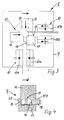
- the device 1 has at its individual welding stations 8 two clamping devices 10 arranged at right angles to one another for detecting in each case two frame legs which are to be joined at right angles to a common corner.
- These clamping devices 10 have between two jaws 10 a and 10 b in the FIGS. 1 to 4 each filled by a frame leg clamping gap, so can each capture a frame legs.
- the clamping devices 10 in addition to their clamping function in the longitudinal direction of its clamping gap and a frame leg held therein are each movable.
- each welding station 8 at the arranged between these two clamping devices 10 Corner a designated as a whole by 11 ultrasonic welding device is arranged. All clamping devices 10 are movable or adjustable in the direction of the corner and to the welding device 11.
- FIG. 1 and 2 are side views.
- FIG. 1 and 2 are side views.
- the common corner connector 7 is inserted into one of these frame legs, for example in the frame leg 3, end side and then mechanically mated with the other frame leg 4 in the direction of its free angle leg 7a before joining two in use position perpendicular to each other frame leg, which in FIG. 6 is indicated by the line Pf1. Since these are relative movements, for example, this other frame leg 4 can be plugged in the direction of the free angle leg 7a on the corner connector 7, which protrudes from the frame leg 3. This plug movement, be it that the frame leg 4 is moved or that the frame leg 3 is moved together with its corner connector 7 is continued until the miter-shaped ends of the frame legs according to FIG. 7 or according to FIG. 10 get in touch with each other. Thereafter, the contact point can be compressed in a manner to be described and the welding process for connecting these miter corners are performed.
- the corner connector 7 are completely inserted and inserted with an angle leg 7a respectively in an associated frame legs, after which the corresponding rectangular next frame legs pushed onto the still free angle leg 7a of this corner connector 7 and thereby expediently slidably clamped.
- first two pairs of angularly assembled frame legs 3 and 4 on the one hand and of angularly assembled frame legs 5 and 6 on the other hand be formed, as in FIG. 7 is indicated. From the frame legs 4 and 6 protrude each angle leg 7a of corner connectors 7, so that these two pairs of angle leg according to the arrows Pf2 to a closed frame 2 according to FIG. 8 can be mechanically assembled and pushed together with the aid of the device 1.
- FIGS. 9 and 10 it is also possible that inserted into each opposite ends of a frame leg 3 and 5 corner connector 7 and two matching frame legs 4 and 6 are pushed parallel to each other and then welded, according to FIG. 10 first the frame legs 4 and 6 according to the arrows Pf3 in FIG. 9 be mated with the corner connectors 7, which protrude from the rectangular frame leg 3, after which then according to the arrows Pf 4 in FIG. 10 the frame leg 5 with his two corner connectors 7 with the frame legs 4 and 6 in turn is mechanically assembled, and vice versa, the intermediate formed from the three frame legs 3, 4 and 6 against the arrows Pf4 could be pushed onto the free angle leg 7a of the frame leg 5 and plugged.
- the device 1 has four ultrasonic welding devices 11 for the four corners of the rectangular spacer frame 2 to be formed, and each welding device 11 has on both sides a clamping device 10 which is oriented and / or movable towards the welding device 11.
- FIGS. 1 and 2 One recognizes in the FIGS. 1 and 2 in that for each frame leg 3, 4, 5 and 6 two clamping devices 10 which detect it result in this way.
- the two perpendicular to each other arranged clamping devices of a corner region are relative to each other in the direction of a frame leg and its clamping gap displaced, so that according to FIG. 2 for example, two according to the FIGS. 6 and 7 individually produced frame angle, ie from two angularly mutually arranged frame legs 3 and 4 or 5 and 6 existing intermediate products of the final spacer frame 2, at their still open sides by means of the clamping devices 10 collapsible and plugged onto the respective free end or the angle leg 7a of a corner connector 7 , what in FIG. 2 is indicated by the arrows Pf 5. It can be seen clearly that it can be sufficient to jointly move two welding stations 8, which detect one of the frame angles, while the other welding stations 8 remain stationary, which leads to the desired relative movement.
- FIG. 2 is further indicated that the clamping devices 10, which perform a relative displacement to the final assembly according to the arrows Pf5, are divided or it is clear that two spaced clamping devices 10 each engage a common frame legs.
- each close clamping device 10 may have a distance of about one-sixth or one eighth or one tenth of a meter or less or even an intermediate value of the imaginary or formed when joining two frame legs corner. The closer the clamping devices 10 are to the respective corner region, the lower is the risk that deformations of the frame legs due to compression or buckling occur during the plugging or joining movements.
- the already mentioned sonotrodes 12 are required.
- the sonotrodes 12 may have a negative right-angled shape for positively supporting and embracing the outside 13 of the corner to be formed, and thus the frame legs Corner, which rests during the welding operation on the outer side 13 of the assembled frame legs.
- the welding device 11 may also have a sonotrode 11 comprising the corner with a projection 12a and a sonotrode 12 spaced therefrom.
- the immediate negative right-angled corner thus arises through the projection 12a.
- two sonotrodes 12 may be arranged at right angles to each other directly in the corner region of the spacer frame 2.
- each hold-down 19 are provided, the two contact to a corner frame leg in the corner at the later formed on the web 14 of the respective frame leg sealing surface in the use position and against a counter-holder 20 or a Press support, where the respective web 15 of the respective frame leg comes to rest, which has the later opposite sealing surface of the spacer frame.
- FIG. 4 It also shows that the corner connector 7 and its angle leg does not have to fill the hollow cross section of the profiles forming the frame legs 3, 4, 5 and 6, but that it is sufficient if this corner connector extends between the outside 13 and the opposite inside of this hollow cross section.
- the frame legs can also opposite FIG. 4 have modified cross-sectional shapes, as in FIG. 14 is indicated.
- FIGS. 1 to 4 can also be seen in the corner regions of the respective welding device 11, ie at the welding stations 8, an abutment 17, which in the position of use of the welding head, so the sonotrode, one of the thickness of the frame leg corresponding distance, said abutment according to FIG. 3 two mutually perpendicular support surfaces 18 has, so the united to a corner two rectangular frame legs in the corner area can support at the same time to absorb the outgoing from the sonotrode forces can.
- the hold-down 19 is easy to see, which can exert a compressive force in the direction of the arrow Pf7, that is in the view according to FIG. 3 approximately perpendicular to the plane takes place.
- the frame legs are pressed together in the corner area against the pad 20.
- the spacer frame 2 produced with the device 1 and according to the described method.
- a rectangular spacer frame 2 for insulating glass panes of particular thermoplastic or weldable synthetic material four each extending between the four corners of such a frame 2 frame legs 3, 4, 5 and 6 connected by means of their ends engaging corner connectors 7 and welded.
- the individual frame legs are mitered at their two free ends or cut with a miter angle of 45 °.
- the common corner connector 7 is inserted into one of these frame legs 3 end and then mated with the other frame leg 4 in the direction of its free angle leg 7 a, either one or the other part is moved in the insertion direction, ie a relative movement between the still free angle leg 7a and the frame leg 4 to be attached takes place.
- This can be carried out in different order at all four corners, wherein after such a joining operation, the welding of each crashing at a corner frame legs by means of ultrasound.
Landscapes
- Engineering & Computer Science (AREA)
- Mechanical Engineering (AREA)
- Civil Engineering (AREA)
- Structural Engineering (AREA)
- Lining Or Joining Of Plastics Or The Like (AREA)
- Joining Of Corner Units Of Frames Or Wings (AREA)
Abstract
Zum Herstellen eines rechteckigen Abstandhalterrahmens (2) für Isolierglasscheiben aus Kunststoff werden vier jeweils zwischen den vier Ecken eines derartigen Rahmens (2) verlaufende Rahmenschenkel (3, 4, 5 und 6) mit Hilfe von ihre Enden eingreifenden Eckverbindern (7) verbunden und verschweißt. Dazu werden die einzelnen Rahmenschenkel an ihren beiden freien Enden auf Gehrung geformt oder geschnitten mit einem Gehrungswinkel von 45°. Vor dem Zusammenfügen jeweils zweier in Gebrauchsstellung rechtwinklig zueinanderstehende Rahmenschenkel z. B. (3 und 4) wird der gemeinsame Eckverbinder (7) in einen dieser Rahmenschenkel (3) endseitig eingesteckt und dann mit dem anderen Rahmenschenkel (4) in Richtung seines freien winkelschenkels (7a) zusammengesteckt, wobei entweder das eine oder das andere Teil in Steckrichtung bewegt wird, also eine Relativbewegung zwischen dem noch freien Winkelschenkel (7a) und dem anzufügenden Rahmenschenkel (4) erfolgt. Dies kann in unterschiedlicher Reihenfolge an allen vier Ecken durchgeführt werden, wobei nach einem derartigen Fügevorgang die Verschweißung der jeweils an einer Ecke zusammenstoßenden Rahmenschenkel mit Hilfe von Ultraschall erfolgt (Figur 2).For producing a rectangular spacer frame (2) for plastic insulating glass panes, four frame members (3, 4, 5 and 6) each extending between the four corners of such a frame (2) are connected and welded by means of corner connectors (7) engaging their ends. For this purpose, the individual frame legs are mitered at their two free ends or cut with a miter angle of 45 °. Before joining in each case two in the use position perpendicular to each other frame legs z. B. (3 and 4), the common corner connector (7) in one of these frame legs (3) inserted end and then with the other frame legs (4) in the direction of its free winkelschenkels (7 a) plugged together, either one or the other part is moved in the direction of insertion, ie a relative movement between the still free angle leg (7 a) and the frame leg to be attached (4). This can be carried out in different order at all four corners, wherein after such a joining operation, the welding of each colliding at a corner frame legs by means of ultrasound (Figure 2).
Description
Die Erfindung betrifft ein Verfahren zum Herstellen eines rechteckigen Abstandhalterrahmens für Isolierglasscheiben aus Kunststoff mit vier jeweils zwischen den vier Rahmenecken angeordneten Rahmenschenkeln und mit in die Enden der Rahmenschenkel eingreifenden Eckverbindern, wobei die Eckverbinder zwei im rechten Winkel zueinander angeordnete Winkelschenkel haben, die in die Rahmenschenkel eingefügt werden, wonach die Rahmenschenkel miteinander verschweißt oder verschmolzen werden.The invention relates to a method for producing a rectangular spacer frame for plastic insulating glass panes with four respectively arranged between the four frame corners frame legs and engaging in the ends of the frame legs corner connectors, wherein the corner connectors have two at right angles arranged angle leg inserted into the frame legs after which the frame legs are welded or fused together.
Ein derartiges Verfahren ist aus der
Zwar sind auch schon Abstandhalterrahmen aus vier in Gebrauchsstellung rechtwinklig zueinander angeordneten Rahmenschenkeln bekannt, die im Eckbereich miteinander verschweißt werden und auf Gehrung geformt sind, wie es beispielsweise aus der
Es besteht deshalb die Aufgabe, ein verfahren der eingangs definierten Art und auch eine Vorrichtung zum Herstellen von Abstandhalterrahmen zu schaffen, womit eine einfache und schnelle Fertigung möglich ist und auch im Eckbereich des entstehenden Abstandhalterrahmens eine möglichst glatte Dichtfläche vorgesehen ist, selbst wenn die Rahmenschenkel aus relativ dünnwandigen Profilen gebildet sind.It is therefore the object to provide a method of the type defined and also an apparatus for producing spacer frame, whereby a simple and fast production is possible and in the corner of the resulting spacer frame the smoothest possible sealing surface is provided, even if the frame legs are formed relatively thin-walled profiles.
Zur Lösung dieser Aufgabe ist das eingangs definierte Verfahren dadurch gekennzeichnet, dass die einzelnen Rahmenschenkel an ihren beiden freien Enden auf Gehrung geformt oder geschnitten werden, dass vor dem Zusammenfügen zweier in Gebrauchsstellung rechtwinklig zueinander stehender Rahmenschenkel der gemeinsame Eckverbinder in einen dieser Rahmenschenkel endseitig eingesteckt und dann mit dem anderen Rahmenschenkel in Richtung seines freien Winkelschenkels maschi nell zusammengesteckt oder der andere Rahmenschenkel in Richtung des freien Winkelschenkels auf diesen aufgesteckt wird, dass die Steckbewegung solange fortgesetzt wird, bis die auf Gehrung geformten Enden der Rahmenschenkel in Berührung miteinander gelangen, und dass die Berührstelle der beiden Rahmenschenkel zusammengedrückt und die Rahmenschenkel an der Berührstelle verschweißt werden.To solve this problem, the method defined at the outset is characterized in that the individual frame legs are mitered at their two free ends or cut that before joining two in use position perpendicular to each other standing frame leg of the common corner connector inserted into one of these frame legs end and then with the other frame leg in the direction of his free angle leg maschi nell put together or the other frame legs in the direction of the free angle leg is attached to this, that the insertion movement is continued until the mitered ends of the frame legs come into contact with each other, and that the contact point of the two frame legs compressed and the frame legs at the contact point be welded.
Dadurch kann erreicht werden, dass die zu verbindenden Rahmenschenkel nicht von vorneherein zusammenhängen müssen, sondern als einzelne Rahmenschenkel mit auf Gehrung geformten Enden verwendet werden können, die nicht oder nicht nur mit dem Eckverbinder, sondern in erster Linie oder ausschließlich miteinander verschweißt sind, so dass sich keine Unebenheiten des Schweißbereiches durch eine Verbindung mit dem innenliegenden Eckverbinder ergibt. Der Eckverbinder muss dabei nicht einmal das gesamte Querschnittsprofil der hohlen Rahmenschenkel ausfüllen, sondern es kann genügen, wenn sein Querschnitt von der Außenseite zur Innenseite des späteren Abstandhalterrahmens reicht, nach den Seiten hin aber innenseitig zu den die Rahmenschenkel bildenden Stegen einen Abstand freilässt.It can thereby be achieved that the frame legs to be connected do not have to be connected from the outset, but can be used as single frame legs with mitred ends which are not or not only welded to the corner connector, but primarily or exclusively to each other, so that no unevenness of the weld area results from a connection with the inner corner connector. The corner connector does not even have to fill the entire cross-sectional profile of the hollow frame legs, but it may suffice if its cross-section extends from the outside to the inside of the later spacer frame, but leaves a distance to the sides inside to the webs forming the frame legs.
Durch das erfindungsgemäße Verfahren können relativ dünnwandige Profile als Rahmenschenkel verarbeitet werden, weil vor allem die Kraft zum Andrücken an die Berührstelle nicht über die Länge des Profiles übertragen werden muss, sondern der Rahmenschenkel insbesondere nahe der Schweißstelle erfasst und dabei auch über eine größere Länge umfasst werden kann, so dass die Kraft in Richtung auf die Schweißstelle auf eine relativ große Fläche des Rahmenschenkels verteilt wird.By the method according to the invention, relatively thin-walled profiles can be processed as frame legs, because above all the force for pressing against the contact point does not have to be transmitted over the length of the profile, but the frame legs are detected in particular near the weld and thereby also covered over a greater length can, so that the force is distributed in the direction of the weld on a relatively large area of the frame leg.
Der Eckverbinder wird zweckmäßigerweise mit einem Winkelschenkel in den ersten Rahmenschenkel vollständig eingefügt und danach kann der zweite Rahmenschenkel auf den noch freien Winkelschenkel des Eckverbinders aufgeschoben und dabei verschiebbar verklemmt werden. Somit kann ein Zwischenprodukt beispielsweise aus zwei durch einen Eckverbinder zusammengesetzten Winkelschenkeln geschaffen werden, das dann mit einem vergleichbaren weiteren Zwischenprodukt zu einem Rahmen zusammengesetzt werden kann, oder es kann in noch zu beschreibender Weise an einem Rahmenschenkel zunächst vorgesehen werden, an den entgegengesetzten Enden jeweils einen Eckverbinder anzubringen und danach den kompletten Rahmen aufzubauen.The corner connector is expediently completely inserted with an angle leg in the first frame legs and then the second frame legs on the still free Angle legs of the corner connector pushed and thereby slidably clamped. Thus, an intermediate product can be created, for example, from two angle legs assembled by a corner connector, which can then be assembled with a comparable further intermediate product into a frame, or it can initially be provided on a frame limb in a manner to be described, at the opposite ends one at a time Corner connector to install and then build the complete frame.
Günstig ist es dabei, wenn der jeweils zunächst mit einem Rahmenschenkel zusammengesteckte Eckverbinder mit seinem zuerst in einen Rahmenschenkel eingefügten Winkelschenkel verschiebbar verklemmt wird. Dadurch wird die Lage des Eckverbinders genügend festgelegt, um das so gebildete Zwischenprodukt während der Herstellung eines kompletten Rahmenschenkels genügend stabil zu gestalten, um dann an den freien Enden solcher Eckverbinder eine Verbindung mit weiteren Rahmenschenkeln vornehmen zu können.It is advantageous in this case if the corner connector, which is in each case initially plugged together with a frame limb, is slidably clamped with its angle limb first inserted into a frame limb. As a result, the position of the corner connector is set sufficiently to make the thus formed intermediate product during the production of a complete frame leg sufficiently stable, in order to then make a connection with other frame legs at the free ends of such corner connector.
Zweckmäßig kann es zum Beispiel auch sein, wenn in beide entgegengesetzten Enden eines Rahmenschenkels Eckverbinder eingefügt und zwei dazu passende Rahmenschenkel parallel zueinander maschinell aufgeschoben oder verschweißt werden, wobei die Relativbewegung zwischen den beiden parallelen Rahmenschenkeln und den quer verlaufenden, schon mit Eckverbindern versehenen Rahmenschenkeln natürlich auch in umgekehrter Richtung erfolgen kann.It may be useful, for example, if inserted into both opposite ends of a frame leg corner connector and two matching frame legs parallel to each other mechanically pushed or welded, the relative movement between the two parallel frame legs and the transverse, provided with corner joints frame legs course also can be done in the opposite direction.
Es ist also auch möglich, dass ein Rahmenschenkel mit zwei Eckverbindern versehen und mit diesen in die freien Enden zweier paralleler, gegebenenfalls schon mit einem ersten rechtwinkligen Rahmenschenkel verbundener Rahmenschenkel eingeschoben und an den Berührstellen verschweißt wird.So it is also possible that a frame legs provided with two corner connectors and inserted with these in the free ends of two parallel, possibly already connected to a first rectangular frame legs frame legs and welded at the contact points.
Das erfindungsgemäße Verfahren lässt sich auch dadurch weiterbilden, dass zwei rechtwinklig zueinander angeordnete Rahmenschenkel miteinander verbunden und am freien Ende eines dieser Rahmenschenkel ein Eckverbinder angebracht und ein zweites Paar von rechtwinklig angeordneten Rahmenschenkeln gebildet und die Eckverbinder in die freien Enden der beiden zum Schließen des Rahmens zu erfassenden Rahmenschenkel eingeschoben werden. Dabei kann variiert werden, in welches freie Ende eines der zusammenzufügenden Rahmenschenkel der Eckverbinder zuerst eingesetzt wird.The method according to the invention can also be further developed by connecting two frame legs arranged at right angles to one another and attaching a corner connector to the free end of one of these frame legs and forming a second pair of frame legs arranged at right angles and the corner connectors into the free ends of the two to close the frame engaging frame legs are inserted. In this case, it can be varied in which free end of one of the frame legs to be joined together, the corner connector is inserted first.
Eine zweckmäßige Realisierung des erfindungsgemäßen Verfahrens kann vorsehen, dass jeweils zwei in Gebrauchsstellung rechtwinklig zueinander angeordnete Rahmenschenkel des zu bildenden Abstandhalterrahmens an einer gemeinsamen Gehrungsstelle mit Hilfe eines Eckverbinders abgestützt und verschweißt werden und dass danach diese beiden jeweils einen Winkel bildenden Rahmenteile in Richtung von aus freien Enden von Rahmenschenkeln vorstehenden Eckverbindern maschinell zusammengeschoben und an den dadurch gebildeten beiden diagonal einander gegenüberliegenden Ecken verschweißt werden.An expedient realization of the method according to the invention can provide that in each case two frame legs of the spacer frame to be formed in the position of use are supported and welded at a common miter point with the aid of a corner connector and that thereafter these two frame parts each forming an angle in the direction of free ends be pushed together by frame limbs protruding corner joints and welded to the thus formed two diagonally opposite corners.
Es ist also möglich, mit dem erfindungsgemäßen Verfahren unterschiedliche Zwischenprodukte zu bilden, bei denen beispielsweise zwei rechtwinklig zueinander stehende Rahmenschenkel zweifach vorgefertigt und dann miteinander verbunden werden oder in dem zunächst an einem querverlaufenden Rahmenschenkel zwei Ecken durch zwei parallele weitere Rahmenschenkel gebildet werden, so dass dann der Rahmen noch mit einem letzten Rahmenschenkel zu schließen ist, dessen beide Enden dabei schon einen Eckverbinder enthalten.It is thus possible to form different intermediates with the method according to the invention, in which, for example, two frame legs standing at right angles to each other are prefabricated twice and then joined together or two corners are first formed on a transverse frame leg by two parallel frame legs, so that then the frame is still to close with a last frame leg, the two ends already contain a corner connector.
Besonders günstig ist es für einen Abstandhalterrahmen aus Kunststoff, wenn die Rahmenschenkel mittels Ultraschall verschweißt werden. Dies lässt sich auch maschinell gut beherrschen und führt zu dauerhaften Schweißverbindungen.It is particularly favorable for a spacer frame made of plastic, when the frame legs are welded by means of ultrasound. This can also be mastered well by machine and leads to permanent welded joints.
Bei einer derartigen Ultraschall-Verschweißung ist es günstig, wenn die Sonotroden der Ultraschall-Schweißvorrichtung an die den inneren Zwischenraum des Rahmens abgewandte Außenseite der zu bildenden jeweiligen Ecke angelegt werden, vorzugsweise in der Weise, dass der Berührbereich der Rahmenschenkel umfasst wird. Entsprechend präzise wird die jeweilige Ecke geschweißt.In such an ultrasonic welding, it is favorable if the sonotrodes of the ultrasonic welding device are applied to the outside of the inner corner of the frame facing away from the respective corner to be formed, preferably in such a way that the contact region of the frame legs is included. Correspondingly precise, the respective corner is welded.
Zumindest die Eckbereiche an den die Dichtstellen des Abstandhalterrahmens bildenden Schenkeln können während des Schweißvorganges niedergehalten und gegen eine Unterlage gedrückt werden. Während also an der späteren Außenseite des Abstandhalterrahmens die Sonotroden zur Anlage kommen, können die quer dazu verlaufenden Dichtstellen des Abstandhalterrahmens ebenfalls eingefasst und an ungewollten Verformungen oder Nahtbildungen gehindert werden, so dass sie die gewünschte glatte Oberfläche behalten oder erhalten.At least the corner areas at the legs forming the sealing points of the spacer frame can be held down during the welding process and pressed against a base. Thus, while the sonotrodes come to rest on the later outer side of the spacer frame, the sealing points of the spacer frame extending transversely thereto can also be edged and prevented from undesired deformations or seaming, so that they retain or maintain the desired smooth surface.
Die eingangs genannte Aufgabe wird außerdem mit einer Vorrichtung zum Herstellen eines rechteckigen Abstandhalterrahmens für Isolierglasscheiben aus Kunststoff mit vier Rahmenschenkeln und vier Eckverbindern, die in die einander zugeWandten Enden der Rahmenschenkel einsteckbar sind und in Gebrauchsstellung eingreifen, wobei die Rahmenschenkel in Gebrauchsstellung in den Eckbereichen miteinander verschweißt sind, dadurch gelöst, dass wenigstens zwei rechtwinklig zueinander angeordnete Klemmeinrichtungen zum Erfassen zweier rechtwinklig an einer gemeinsamen Ecke zusammenzufügender Rahmenschenkel vorgesehen sind, dass wenigstens eine dieser Klemmvorrichtungen in Richtung der Orientierung ihres Klemmspalts und eines darin gehaltenen Rahmenschenkels bewegbar ist, dass an der zwischen diesen beiden Klemmeinrichtungen angeordneten Ecke eine Ultraschall-Schweißvorrichtung angeordnet ist und dass die Sonotroden dieser Ultraschall-Schweißvorrichtung für ein formschlüssiges Abstützen und Umfassen der Außenseite der zu bildenden Ecke eine negative rechtwinklige Ecke aufweisen, die während des Schweißvorganges an der Außenseite der zusammengefügten und zusammengeschobenen Rahmenschenkel anliegt, oder dass die Ultraschall-Schweißvorrichtung eine die Ecke mit einem Vorsprung umfassende Sonotrode und eine dazu beabstandete Sonotrode aufweist.The object mentioned at the outset is also provided with a device for producing a rectangular spacer frame for plastic insulating glass panes with four frame legs and four corner connectors which can be inserted into the mutually facing ends of the frame legs and engage in the position of use, wherein the frame legs welded together in the use position in the corner regions are achieved in that at least two mutually perpendicular clamping means are provided for detecting two perpendicular to be joined together at a common corner frame legs, that at least one of these Clamping devices is movable in the direction of the orientation of its nip and a frame leg held therein, that at the corner arranged between these two clamping means an ultrasonic welding device is arranged and that the sonotrodes this ultrasonic welding device for a form-fitting supporting and embracing the outside of the corner to be formed have a negative right-angled corner, which bears against the outside of the assembled and collapsed frame legs during the welding operation, or that the ultrasonic welding device has a sonotrode comprising the corner with a projection and a sonotrode spaced therefrom.
Somit können die an einer Ecke zu verbindenden Rahmenschenkel maschinell erfasst und in ihrem gemeinsamen Eckbereich zusammengebracht werden, indem eine der Klemmeinrichtungen die entsprechende Bewegung durchführt, wobei zuvor schon die Eckverbinder in entsprechender Weise angebracht worden sind. Die Sonotroden können dabei die Außenseite der Rahmenschenkel im Bereich ihrer gegenseitigen Berührung formschlüssig abstützen und erfassen und erlauben während des Schweißvorganges somit keine Verformung aus ihrer Winkligkeit heraus, so dass die außen liegenden Eckbereiche des Abstandhalterrahmens präzise geformt werden können.Thus, the frame legs to be connected to a corner can be detected by machine and brought together in their common corner by one of the clamping devices performs the corresponding movement, previously the corner connectors have been mounted in a corresponding manner. The sonotrodes can positively support the outer side of the frame legs in the region of their mutual contact and thus do not allow any deformation during the welding process out of their angularity, so that the outer corner regions of the spacer frame can be precisely shaped.
Besonders günstig ist es, wenn alle Klemmvorrichtungen jeweils in Richtung zu der Ecke und der Schweißvorrichtung hin bewegbar oder verstellbar sind. Dies ergibt eine besonders vielseitig anwendbare Vorrichtung, um die Rahmenschenkel eines Abstandhalterrahmens maschinell zusammenzuführen, aneinanderzudrücken und dann im Eckbereich verschweißen zu können.It is particularly favorable when all clamping devices are movable or adjustable in the direction of the corner and the welding device. This results in a particularly versatile applicable device for mechanically bringing together the frame legs of a spacer frame, to press together and then to weld in the corner.
Für die Herstellung eines rechteckigen Abstandhalterrahmens mit vier auf Gehrung geschnittenen und zu verbindenden Rahmenschenkeln ist es besonders günstig, wenn die erfindungsgemäße Vorrichtung vier Ultraschall-Schweißvorrichtungen für die vier zu bildenden Ecken des Abstandhalterrahmens aufweist und jeder Schweißvorrichtung beidseits eine Klemmeinrichtung zugeordnet ist, die zu der Schweißvorrichtung hin orientiert und/oder bewegbar ist. Somit können einzelne oder schon teilweise verbundene Rahmenschenkel erfasst und nacheinander verbunden werden, bis der Abstandhalterrahmen fertiggestellt ist. Die Klemmeinrichtungen dienen dabei dann dazu, jeweils den einen oder den anderen Rahmenschenkel auf einen noch freien Winkelschenkel eines schon teilweise eingesetzten Eckverbinders aufzuschieben, um anschließend dann die Schweißung durchzuführen.For the production of a rectangular spacer frame with four mitered and connected frame legs, it is particularly advantageous if the device according to the invention has four ultrasonic welding devices for the four corners of the spacer frame to be formed and each welding device is assigned on both sides of a clamping device to the welding device oriented and / or movable. Thus, individual or already partially connected frame legs can be detected and connected in succession until the spacer frame is completed. The clamping devices are then used to postpone one or the other frame legs on a still free angle leg of a corner connector already partially inserted, then then perform the weld.
Zumindest zwei rechtwinklig zueinander angeordnete Klemmeinrichtungen können mit der im Eckbereich zwischen ihnen befindlichen Schweißvorrichtung relativ zu den weiteren Klemmeinrichtungen in Richtung eines Rahmenschenkels verschiebbar sein, so dass zwei einzeln hergestellte Rahmenwinkel an ihren noch offenen Seiten mittels der Klemmeinrichtungen zusammenschiebbar und auf das freie Ende eines Eckverbinders steckbar sind. Es ist also durch diese Ausgestaltung möglich, zwei rechtwinklig zueinander angeordnete Rahmenschenkel mit Hilfe eines Eckverbinders zu verbinden, dasselbe mit zwei weiteren Rahmenschenkeln zu machen und dann in jeweils freie Enden der Rahmenschenkel Eckverbinder einzustecken, um dann die zunächst jeweils aus zwei rechtwinklig zueinander angeordneten Rahmenschenkeln gebildeten Rahmenwinkel endgültig zusammenzuschieben und dabei die offenen Enden jeweils eines Rahmenschenkels auf einen Winkelschenkel eines der Eckverbinder aufzustecken. Somit kann mit der Vorrichtung einerseits jeweils ein derartiger Rahmenwinkel gefertigt und durch die relative Verschiebbarkeit zweier Klemmeinrichtungen mit Schweißverbindung dann ein derartiger Rahmenwinkel relativ zu dem anderen Rahmenwinkel zum Schließen des gesamten Abstandhalterrahmens verstellt werden.At least two clamping devices arranged at right angles to one another can be displaceable relative to the further clamping devices in the direction of a frame leg with the welding device located in the corner region between them so that two individually produced frame angles can be pushed together at their still open sides by means of the clamping devices and plugged onto the free end of a corner connector are. It is thus possible by this configuration to connect two mutually perpendicular frame legs by means of a corner connector to do the same with two other frame legs and then insert into each free ends of the frame leg corner connector, then the first each formed from two mutually perpendicular frame legs formed Frame frame finally collapse while aufzustecken the open ends of each frame leg on an angle leg of the corner connector. Thus, with the device on the one hand in each case such a frame angle made and by the relative Displaceability of two clamping devices with welded connection then such a frame angle relative to the other frame angle to close the entire spacer frame can be adjusted.
Zumindest diejenigen Klemmeinrichtungen, die eine Verschiebung zum endgültigen Zusammenfügen zweier schon vorgefügter Rahmenteile dienen, können unterteilt oder aus zwei beabstandeten Klemmeinrichtungen gebildet sein, deren Klemmfugen also miteinander fluchten, und die dem freien Ende eines zufügenden Rahmenschenkels nähere Klemmeinrichtung dieser beiden Klemmeinrichtungen kann zunächst zum Aufbau einer ein Ausknicken des Rahmenschenkels bei dem Fügevorgang verhindernden Zugspannung in dem von ihr erfassten Rahmenschenkel dienen. Wenn also zwei Klemmeinrichtungen miteinander fluchtend an einem Rahmenschenkel angreifen, der beispielsweise durch die Verschiebung der Klemmeinrichtungen auf einen freien Winkelschenkel eines Eckverbinders aufgeschoben werden soll, kann zunächst die der Ecke nähere Klemmeinrichtung in Schieberichtung bewegt oder zumindest unter Spannung gesetzt werden, so dass in dem erfassten Rahmenschenkel die erwähnte Zugspannung entsteht. Dadurch kann verhindert werden, dass bei dem schon erwähnten Steckvorgang dieser Rahmenschenkel zu sehr in Schieberichtung unter Druck gesetzt wird und gegebenenfalls ausknickt.At least those clamping devices that serve a shift to the final assembly of two already vorgemgter frame parts may be divided or formed of two spaced clamping devices, the clamping joints thus aligned with each other, and the free end of a Zufügenden frame leg closer clamping device of these two clamping devices can first to build a a buckling of the frame leg in the joining operation preventing tensile stress in the frame leg detected by it serve. Thus, if two clamping devices engage in alignment with each other on a frame leg, which is to be pushed, for example, by the displacement of the clamping devices on a free angle leg of a corner connector, the clamping device closer to the corner can first be moved in the sliding direction or at least put under tension, so that in the detected Frame legs the mentioned tension arises. This can prevent that in the already mentioned plug-in operation of this frame legs is set too much in the sliding direction under pressure and possibly buckles.
Besonders günstig ist es, wenn bei der erfindungsgemäßen Vorrichtung an allen vier Seiten jeweils Klemmeinrichtungen doppelt und beabstandet vorgesehen sind, was die größte Vielseitigkeit der Vorrichtung für das Herstellen eines Abstandhalterrahmens ergibt.It is particularly advantageous if, in the device according to the invention, clamping devices are provided twice and at a distance on all four sides, which results in the greatest versatility of the device for producing a spacer frame.
Die einer Ecke oder Schweißvorrichtung nahe Klemmeinrichtung kann von der gedachten oder beim zusammenfügen eines Rahmenschenkels gebildeten Ecke einen Abstand von etwa einem sechstel oder einem achtel oder einem zehntel Meter oder weniger oder einem Zwischenwert davon haben. Je näher die Klemmeinrichtung der jeweiligen Ecke ist, umso geringer ist die Gefahr einer Knickbelastung eines Rahmenschenkels bei seiner Verschiebung in seiner Längsrichtung, um ihn auf einen Winkelschenkels eines Eckverbinders aufzustecken, selbst wenn dabei eine Reibkraft zu überwinden ist, damit danach der Eckverbinder mit dem Rahmenschenkel reibend oder klemmend verbunden ist.The clamping device close to a corner or welding device can be of the imaginary or when assembling a frame leg have a distance of about one sixth or one eighth or one tenth meter or less or an intermediate value thereof. The closer the clamping device of the respective corner is, the lower the risk of buckling load of a frame leg in its displacement in its longitudinal direction to aufzustecken it on an angle leg of a corner connector, even if a frictional force is overcome, then the corner connector with the frame legs is connected rubbing or clamping.
Für den Eckbereich der Vorrichtung können etwa zwischen den Klemmeinrichtungen Niederhalter vorgesehen sein, die jeweils zwei zu einer Ecke zu verbindende Rahmenschenkel im Eckbereich an der späteren Dichtfläche des Abstandhalterrahmens in Gebrauchsstellung berühren und gegen einen Gegenhalter oder eine Auflage drücken. Somit wird auch der für die Abdichtung wichtige Teilbereich des Abstandhalterrahmens rechtwinklig zu den Außenseiten glatt gehalten und an eventuellen Verformungen durch den Schweißvorgang gehindert.For the corner region of the device, hold-downs may be provided between the clamping devices, for example, each touching two frame legs to be connected to a corner in the corner area on the later sealing surface of the spacer frame in the use position and pressing against a counter holder or support. Thus, also important for the sealing portion of the spacer frame is kept straight at right angles to the outer sides and prevented from any deformation by the welding process.
Eine weitere zweckmäßige Ausgestaltung der Vorrichtung kann vorsehen, dass in den Eckbereichen der jeweiligen Schweißvorrichtung oder dem Schweißkopf ein Widerlager zugeordnet ist, welches in Gebrauchsstellung von dem Schweißkopf einen der Dicke des Rahmenschenkels entsprechenden Abstand hat und wenn das Widerlager vorzugsweise zwei rechtwinklig zueinander angeordnete, der Schweißvorrichtung zugewandte und den Wirkflächen der Sonotroden parallele Stützfläche hat. Somit wird auch die Innenseite des Abstandhalterrahmens während des Schweißvorganges in Form gehalten und an einer unerwünschten Verformung gehindert. Vor allem bei Kombination der vorbeschriebenen Merkmale und Maßnahmen wird der gesamte Eckbereich während des Schweißvorganges präzise umschlossen, so dass der Abstandhalterrahmen im Eckbereich auch nach dem Schweißvorgang den gewünschten, außenseitig ebenen und glatten Gesamtquerschnitt hat und behält.A further advantageous embodiment of the device can provide that in the corner regions of the respective welding device or the welding head an abutment is assigned, which in the use position of the welding head has a thickness corresponding to the frame leg distance and if the abutment preferably two mutually perpendicular, the welding device facing and the active surfaces of the sonotrodes parallel support surface has. Thus, the inside of the spacer frame is kept in shape during the welding process and prevented from undesirable deformation. Especially when combining the above-described features and measures, the entire corner area is precisely enclosed during the welding process, so that the spacer frame in the corner area has the desired, externally flat and smooth overall cross-section even after the welding process and retains.
Vor allem bei Kombination einzelner oder mehrerer der vorbeschriebenen Verfahrens- und vorrichtungsmerkmale ist es möglich, einen Abstandhalterrahmen mit vier auf Gehrung geschnittenen Ecken im Wesentlichen maschinell aufzubauen und die vier Ecken mittels Ultraschall zu verschweißen. Da ein reines Verschweißen der Ecken die Gefahr einer ungewollten Verformung und/oder einer unzureichenden Stabilität mit sich bringt, ist vorgesehen, in die vier Rahmenecken jeweils in entsprechender Reihenfolge Eckverbinder einzusetzen, die den Innenquerschnitt des Rahmenprofils zumindest in Richtung von der Außenseite zur Innenseite hin ausfüllen.Especially when combining one or more of the above-described method and device features, it is possible to machine a spacer frame with four mitred corners substantially mechanically and to weld the four corners by means of ultrasound. Since a pure welding of the corners brings the risk of unwanted deformation and / or inadequate stability, it is provided to insert corner connectors into the four frame corners, each in a corresponding sequence, which fill the inner cross section of the frame profile at least in the direction from the outside to the inside ,
Nachstehend sind Ausführungsbeispiele der Erfindung anhand der Zeichnung näher beschrieben. Es zeigt in zum Teil erheblich schematisierter Darstellung:
- Fig. 1:
- eine Ansicht einer erfindungsgemäßen Vorrichtung zum maschinellen Herstellen von rechteckigen Abstandhalterrahmen für Isolierglasscheiben mit vier zusammenwirkenden Schweißstationen, an denen jeweils zwei rechtwinklig zueinander angeordnete Rahmenschenkel nach dem Einfügen von Eckverbindern an ihren auf Gehrung geformten Berührstellen verschweißbar sind,
- Fig. 2:
- eine der
Figur 1 entsprechende Darstellung während eines Fügevorgangs, bei welchem zwei jeweils schon rechtwinklig zueinander angeordnete Rahmenschenkelpaare zusammengeschoben und zusammengesteckt werden, wonach die inFigur 2 - Fig. 3:
- in vergrößertem Maßstab eine Ansicht einer der Schweißstationen der Vorrichtung gemäß den
Figuren 1 und2 , - Fig. 4:
- einen Schnitt durch den Eckbereich der Schweißstation, wobei ein Rahmenschenkel und ein Winkelschenkel eines Eckverbinders im Querschnitt dargestellt sind,
- Fig. 5:
- das Prinzip der Verbindung zweier Rahmenschenkel, nachdem der Eckverbinder in einem Rahmenschenkel bereits eingesteckt ist und der zweite Winkelschenkel mit einem zweiten Rahmenschenkel zusammensteckbar ist,
- Fig. 6:
- eine Möglichkeit, einen Abstandhalterrahmen dadurch zu bilden, dass jeweils einer der vier Rahmenschenkel an einem Ende mit einem Eckverbinder versehen wird, der zum Zusammenstecken mit einem Nachbarrahmenschenkel vorgesehen ist, bevor dieser Steckvorgang durchgeführt ist,
- Fig. 7:
- eine Darstellung, in welcher jeweils rechtwinklig zueinander verlaufende Rahmenschenkel an einer gemeinsamen Ecke zusammengesteckt sind und diese Paare von Rahmenschenkel miteinander an diagonal gegenüberliegenden Ecken zusammensteckbar sind,
- Fig. 8:
- den durch die verschiedenen Steck- und Fügebewegungen gemäß
den Figuren 6 und 7 gebildeten Abstandhalterrahmen, - Fig. 9:
- eine abgewandelte Vorgehensweise, bei welcher zwei in Gebrauchsstellung einander gegenüberliegende parallele Rahmenschenkel an beiden Enden mit Eckverbindern versehen sind und die rechtwinklig dazu stehenden Rahmenschenkel auf die freien Enden der Eckverbinder eines dieser Rahmenschenkel aufsteckbar sind,
- Fig. 10:
- die Einfügung des zweiten, jeweils zwei Eckverbinder aufweisenden Rahmenschenkels in die mit dem ersten querverlaufenden Rahmenschenkel bereits zusammengesteckten Rahmenschenkel, wodurch wiederum ein Rahmen gemäß
Fig. 8 entsteht, - Fig. 11:
- die Anordnung einer Sonotrode einer Ultraschall-Schweißvorrichtung an einer zuvor gebildeten Ecke des Rahmens während des Schweißvorganges, wobei die Sonotrode eine negative rechtwinklige Ecke zum Umfassen der Rahmenecke aufweist,
- Fig. 12:
- eine gegenüber
Fig. 11 abgewandelte Anordnung von Sonotroden, deren eine einen die Ecke umgreifenden Vorsprung hat, welchem eine zweite Sonotrode benachbart ist, - Fig. 13:
- eine abgewandelte Ausführungsform, bei welcher zwei einzelne Sonotroden den Eckbereich eines Rahmens beaufschlagen, sowie
- Fig. 14:
- fünf Beispiele von möglichen Querschnitten der Rahmenschenkel des Abstandhalterrahmens.
- Fig. 1:
- a view of an apparatus according to the invention for the manufacture of rectangular spacer frame for insulating glass panes with four cooperating welding stations, on each of which two mutually perpendicular frame legs are welded after inserting corner connectors at their mitered contact points,
- Fig. 2:
- one of the
FIG. 1 corresponding representation during a joining operation in which two each already at right angles arranged frame leg pairs are pushed together and put together, after which the inFIG. 2 still open Corner areas are welded, - 3:
- on an enlarged scale, a view of one of the welding stations of the device according to the
FIGS. 1 and2 . - 4:
- a section through the corner region of the welding station, wherein a frame leg and an angle leg of a corner connector are shown in cross section,
- Fig. 5:
- the principle of the connection of two frame legs, after the corner connector is already inserted in a frame leg and the second angle leg is mated with a second frame legs,
- Fig. 6:
- a possibility of forming a spacer frame in that one of the four frame legs is provided at one end with a corner connector which is provided for mating with a neighboring frame leg before this insertion process is carried out,
- Fig. 7:
- a representation in which each mutually perpendicular frame legs are plugged together at a common corner and these pairs of frame legs are joined together at diagonally opposite corners,
- Fig. 8:
- the by the various plug-in and joining movements according to the
FIGS. 6 and 7 formed spacer frame, - Fig. 9:
- a modified procedure in which two in the position of use opposing parallel frame legs are provided at both ends with corner connectors and perpendicular standing frame legs are attachable to the free ends of the corner connector of one of these frame legs,
- Fig. 10:
- the insertion of the second, each two corner joints having frame leg in the already merged with the first transverse frame leg frame legs, which in turn a frame according to
Fig. 8 arises - Fig. 11:
- the arrangement of a sonotrode of an ultrasonic welding device at a previously formed corner of the frame during the welding process, wherein the sonotrode has a negative right-angled corner for embracing the frame corner,
- Fig. 12:
- one opposite
Fig. 11 modified arrangement of sonotrodes, one of which has a corner embracing projection, which is adjacent to a second sonotrode, - Fig. 13:
- a modified embodiment in which two individual sonotrodes act on the corner of a frame, as well as
- Fig. 14:
- five examples of possible cross sections of the frame legs of the spacer frame.
Eine im Ganzen mit 1 bezeichnete, in den
Gemäß
Demgemäß ist wichtig, dass die Vorrichtung 1 an ihren einzelnen Schweißstationen 8 zwei rechtwinklig zueinander angeordnete Klemmeinrichtungen 10 zum Erfassen von jeweils zwei rechtwinklig an einer gemeinsamen Ecke zusammenzufügender Rahmenschenkel aufweist. Diese Klemmeinrichtungen 10 haben zwischen zwei Klemmbacken 10a und 10b einen in den
Außerdem ist an jeder Schweißstation 8 an der zwischen diesen beiden Klemmeinrichtungen 10 angeordneten Ecke eine im Ganzen mit 11 bezeichnete Ultraschall-Schweißvorrichtung angeordnet. Alle Klemmvorrichtungen 10 sind dabei in Richtung zu der Ecke und zu der Schweißvorrichtung 11 hin bewegbar oder verstellbar.In addition, at each
Es sei erwähnt, dass die Vorrichtung 1 im Ausführungsbeispiel etwa vertikal oder unter einem spitzen Schrägungswinkel angeordnet ist, d.h.
In den
Gemäß
Gemäß den
Gemäß den
Es wurde schon mehrfach erwähnt, dass die Rahmenschenkel 3, 4, 5 und 6 nach dem Zusammenführen ihrer auf Gehrung geformten und zueinander passenden Enden an ihren Berührstellen verschweißt werden. Dies geschieht zweckmäßigerweise mit Hilfe von Ultraschall, indem in
In den
Man erkennt in den
In
Dabei ist gemäß den
Es sei an dieser Stelle erwähnt, dass die durch die Pfeile Pf1 bis Pf5 angedeuteten Bewegungen entsprechender Teile auch durch entgegengesetzte Bewegungen der jeweils anderen Teile ersetzt werden könnten, die Pfeile also zwar bevorzugte Bewegungen einerseits, andererseits aber auch ganz allgemein entsprechende Relativbewegungen bedeuten.It should be mentioned at this point that the indicated by the arrows Pf1 to Pf5 movements of corresponding parts could also be replaced by opposite movements of the other parts, the arrows so although preferred movements on the one hand, on the other hand but also quite generally corresponding relative movements.
Die einer Ecke oder Schweißvorrichtung 11 jeweils nahe Klemmeinrichtung 10 kann von der gedachten oder beim Zusammenfügen zweier Rahmenschenkel gebildeten Ecke einen Abstand von etwa einem sechstel oder einem achtel oder einem zehntel Meter oder weniger oder auch einem Zwischenwert davon haben. Je näher die Klemmeinrichtungen 10 dem jeweiligen Eckbereich sind, umso geringer ist die Gefahr, dass bei den Steck- oder Fügebewegungen Verformungen der Rahmenschenkel durch Stauchen oder Knicken entstehen.The cornering or
Für die mehrfach erwähnte Ultraschall-Verschweißung der Rahmenschenkel 3, 4, 5 und 6 an ihren gegenseitigen Berührstellen sind die schon erwähnten Sonotroden 12 erforderlich. Gemäß
Gemäß
Schließlich können gemäß
In den
In den
Bei gemeinsamer Betrachtung der
Zum Herstellen eines rechteckigen Abstandhalterrahmens 2 für Isolierglasscheiben aus insbesondere thermoplastischem Kunststoff oder aus schweißbarem synthetischem Werkstoff werden vier jeweils zwischen den vier Ecken eines derartigen Rahmens 2 verlaufende Rahmenschenkel 3, 4, 5 und 6 mit Hilfe von ihre Enden eingreifenden Eckverbindern 7 verbunden und verschweißt. Dazu werden die einzelnen Rahmenschenkel an ihren beiden freien Enden auf Gehrung geformt oder geschnitten mit einem Gehrungswinkel von 45°. Vor dem Zusammenfügen jeweils zweier in Gebrauchsstellung rechtwinklig zueinanderstehende Rahmenschenkel z. B. 3 und 4 wird der gemeinsame Eckverbinder 7 in einen dieser Rahmenschenkel 3 endseitig eingesteckt und dann mit dem anderen Rahmenschenkel 4 in Richtung seines freien Winkelschenkels 7a zusammengesteckt, wobei entweder das eine oder das andere Teil in Steckrichtung bewegt wird, also eine Relativbewegung zwischen dem noch freien Winkelschenkel 7a und dem anzufügenden Rahmenschenkel 4 erfolgt. Dies kann in unterschiedlicher Reihenfolge an allen vier Ecken durchgeführt werden, wobei nach einem derartigen Fügevorgang die Verschweißung der jeweils an einer Ecke zusammenstoßenden Rahmenschenkel mit Hilfe von Ultraschall erfolgt.To produce a
Claims (15)
Priority Applications (1)
| Application Number | Priority Date | Filing Date | Title |
|---|---|---|---|
| PL09010716T PL2159366T3 (en) | 2008-08-28 | 2009-08-20 | Method and device for producing a square spacer frame for insulating glass panes |
Applications Claiming Priority (1)
| Application Number | Priority Date | Filing Date | Title |
|---|---|---|---|
| DE200810044771 DE102008044771B3 (en) | 2008-08-28 | 2008-08-28 | Method and device for producing a rectangular spacer frame for insulating glass panes |
Publications (3)
| Publication Number | Publication Date |
|---|---|
| EP2159366A2 true EP2159366A2 (en) | 2010-03-03 |
| EP2159366A3 EP2159366A3 (en) | 2012-05-09 |
| EP2159366B1 EP2159366B1 (en) | 2016-11-16 |
Family
ID=41138763
Family Applications (1)
| Application Number | Title | Priority Date | Filing Date |
|---|---|---|---|
| EP09010716.0A Active EP2159366B1 (en) | 2008-08-28 | 2009-08-20 | Method and device for producing a square spacer frame for insulating glass panes |
Country Status (3)
| Country | Link |
|---|---|
| EP (1) | EP2159366B1 (en) |
| DE (1) | DE102008044771B3 (en) |
| PL (1) | PL2159366T3 (en) |
Cited By (3)
| Publication number | Priority date | Publication date | Assignee | Title |
|---|---|---|---|---|
| EP3181792A1 (en) * | 2015-12-17 | 2017-06-21 | Rottler und Rüdiger und Partner GmbH | Corner connector, spacer frame, insulating glass pane and method for producing of a spacer frame |
| WO2017115062A1 (en) * | 2015-12-31 | 2017-07-06 | Saint-Gobain Glass France | Method and system for manufacturing an insulating glazing unit |
| WO2023161213A1 (en) * | 2022-02-24 | 2023-08-31 | Saint-Gobain Glass France | Device and method for automatically assembling a polymeric spacer for insulation glazings |
Families Citing this family (4)
| Publication number | Priority date | Publication date | Assignee | Title |
|---|---|---|---|---|
| DE102013008768A1 (en) | 2013-05-23 | 2014-11-27 | Rottler und Rüdiger und Partner GmbH | Method and device for feeding corner connectors to a plug-in station |
| WO2020200622A1 (en) | 2019-03-29 | 2020-10-08 | Saint-Gobain Glass France | Method for producing an insulating glass unit |
| WO2020200621A1 (en) | 2019-03-29 | 2020-10-08 | Saint-Gobain Glass France | Hollow-profile spacer with pre-applied sealing compound |
| EP3770369A1 (en) | 2019-07-23 | 2021-01-27 | Saint-Gobain Glass France | Bearing device for hollow profile spacers |
Citations (2)
| Publication number | Priority date | Publication date | Assignee | Title |
|---|---|---|---|---|
| EP1030024A2 (en) | 1999-02-16 | 2000-08-23 | Peter Lisec | Procedure and device for fabricating spacer elements for insulating glazing made of hollow profiles |
| WO2007014720A1 (en) | 2005-08-01 | 2007-02-08 | Technoform Caprano Und Brunnhofer Gmbh & Co. Kg | Spacer arrangement with fusable connector for insulating glass units |
Family Cites Families (5)
| Publication number | Priority date | Publication date | Assignee | Title |
|---|---|---|---|---|
| DE2821133C2 (en) * | 1978-05-13 | 1980-06-26 | Rehau Plastiks Ag & Co, 8673 Rehau | Method of joining the ends of mitered hollow profiles |
| DE2911831C2 (en) * | 1979-03-26 | 1982-10-21 | Glas - und Spiegel-Manufactur AG, 4650 Gelsenkirchen | Device for producing spacer frames for insulating glass panes |
| DE3318684A1 (en) * | 1983-05-21 | 1984-11-22 | Wilh. Frank Gmbh, 7022 Leinfelden-Echterdingen | METHOD FOR PRODUCING FRAME FOR WINDOWS, DOORS FROM PLASTIC PROFILES, IN PARTICULAR WING FRAME, AND FRAME MADE THEREFOR |
| BE1002510A6 (en) * | 1988-09-28 | 1991-03-05 | Atlas Isolaties Pv | Corner connection for frames for double glazed and profiles hereby used. |
| US7739851B2 (en) * | 2003-06-23 | 2010-06-22 | Ppg Industries Ohio, Inc. | Plastic spacer stock, plastic spacer frame and multi-sheet unit, and method of making same |
-
2008
- 2008-08-28 DE DE200810044771 patent/DE102008044771B3/en active Active
-
2009
- 2009-08-20 EP EP09010716.0A patent/EP2159366B1/en active Active
- 2009-08-20 PL PL09010716T patent/PL2159366T3/en unknown
Patent Citations (2)
| Publication number | Priority date | Publication date | Assignee | Title |
|---|---|---|---|---|
| EP1030024A2 (en) | 1999-02-16 | 2000-08-23 | Peter Lisec | Procedure and device for fabricating spacer elements for insulating glazing made of hollow profiles |
| WO2007014720A1 (en) | 2005-08-01 | 2007-02-08 | Technoform Caprano Und Brunnhofer Gmbh & Co. Kg | Spacer arrangement with fusable connector for insulating glass units |
Cited By (5)
| Publication number | Priority date | Publication date | Assignee | Title |
|---|---|---|---|---|
| EP3181792A1 (en) * | 2015-12-17 | 2017-06-21 | Rottler und Rüdiger und Partner GmbH | Corner connector, spacer frame, insulating glass pane and method for producing of a spacer frame |
| WO2017115062A1 (en) * | 2015-12-31 | 2017-07-06 | Saint-Gobain Glass France | Method and system for manufacturing an insulating glazing unit |
| FR3046415A1 (en) * | 2015-12-31 | 2017-07-07 | Saint Gobain | METHOD AND INSTALLATION FOR MANUFACTURING INSULATING GLAZING |
| CN108431358A (en) * | 2015-12-31 | 2018-08-21 | 法国圣戈班玻璃厂 | Method and apparatus for manufacturing an insulating glazing unit |
| WO2023161213A1 (en) * | 2022-02-24 | 2023-08-31 | Saint-Gobain Glass France | Device and method for automatically assembling a polymeric spacer for insulation glazings |
Also Published As
| Publication number | Publication date |
|---|---|
| EP2159366A3 (en) | 2012-05-09 |
| EP2159366B1 (en) | 2016-11-16 |
| PL2159366T3 (en) | 2017-07-31 |
| DE102008044771B3 (en) | 2009-11-26 |
Similar Documents
| Publication | Publication Date | Title |
|---|---|---|
| EP2159366B1 (en) | Method and device for producing a square spacer frame for insulating glass panes | |
| DE102017111606B4 (en) | Method and device for welding two hollow plastic profile bars | |
| DE102015013439B4 (en) | Process and device for welding profile bars made of plastic | |
| EP3291965B1 (en) | Method and device for connecting profile parts | |
| AT403350B (en) | BENDING MACHINE FOR MANUFACTURING A SPACING INTERNAL FRAME FOR AN INSULATED GLASS DISC | |
| DE69102000T2 (en) | Pipe and manufacturing method. | |
| DE2647715A1 (en) | CORNER CONNECTION FOR A FRAMEWORK FORMED FROM HOLLOW PLASTIC PROFILES AND A METHOD FOR MANUFACTURING IT | |
| DE60006917T2 (en) | Closed structural part | |
| DE102014118368B3 (en) | Method and device for producing a corner joint | |
| DE3039733A1 (en) | Butt welding mitred thermoplastic frames - in which pressed out weld polymer fills lateral slots to keep outer surfaces clean | |
| DE102019109294B4 (en) | Process for welding profile bars | |
| DE102018115382B4 (en) | Joining of sheet metal end sections by means of forming | |
| EP1931494B1 (en) | Joining element | |
| DE2000354A1 (en) | Rod or tubular construction element | |
| DE2757886A1 (en) | Corner connection for metal door frame - has sections of tubes punched in cut=outs in corner pieces | |
| EP0796720B1 (en) | Process for making frames | |
| DE102007035962A1 (en) | Method and apparatus for forming a welded joint | |
| DE60011681T2 (en) | METHOD FOR CONNECTING BARS TO MOUNTING A FRAME STRUCTURE | |
| DE102011001497A1 (en) | Connecting element for structurally engineered formwork system, has connection point provided with overlap of sheet metal area of bracket with another sheet metal area of another bracket | |
| EP3414078A1 (en) | Method and device for connecting profiled parts | |
| DE9015416U1 (en) | Scaffolding node | |
| DE2015414A1 (en) | Joining hollow sections to form window frames etc | |
| WO2017157914A1 (en) | Device and method for connecting profiled parts | |
| WO2019002443A1 (en) | METHOD FOR PRODUCING A STEEL PROFILE | |
| CH640299A5 (en) | Composite profile, in particular for window frames or door frames |
Legal Events
| Date | Code | Title | Description |
|---|---|---|---|
| PUAI | Public reference made under article 153(3) epc to a published international application that has entered the european phase |
Free format text: ORIGINAL CODE: 0009012 |
|
| AK | Designated contracting states |
Kind code of ref document: A2 Designated state(s): AT BE BG CH CY CZ DE DK EE ES FI FR GB GR HR HU IE IS IT LI LT LU LV MC MK MT NL NO PL PT RO SE SI SK SM TR |
|
| AX | Request for extension of the european patent |
Extension state: AL BA RS |
|
| RIN1 | Information on inventor provided before grant (corrected) |
Inventor name: ROTTLER, ROLAND |
|
| PUAL | Search report despatched |
Free format text: ORIGINAL CODE: 0009013 |
|
| RAP1 | Party data changed (applicant data changed or rights of an application transferred) |
Owner name: ROTTLER UND RUEDIGER UND PARTNER GMBH |
|
| AK | Designated contracting states |
Kind code of ref document: A3 Designated state(s): AT BE BG CH CY CZ DE DK EE ES FI FR GB GR HR HU IE IS IT LI LT LU LV MC MK MT NL NO PL PT RO SE SI SK SM TR |
|
| AX | Request for extension of the european patent |
Extension state: AL BA RS |
|
| RIC1 | Information provided on ipc code assigned before grant |
Ipc: E06B 3/673 20060101AFI20120330BHEP Ipc: E06B 3/96 20060101ALI20120330BHEP |
|
| 17P | Request for examination filed |
Effective date: 20120929 |
|
| REG | Reference to a national code |
Ref country code: DE Ref legal event code: R079 Ref document number: 502009013371 Country of ref document: DE Free format text: PREVIOUS MAIN CLASS: E06B0003673000 Ipc: B29C0065000000 |
|
| GRAP | Despatch of communication of intention to grant a patent |
Free format text: ORIGINAL CODE: EPIDOSNIGR1 |
|
| RIC1 | Information provided on ipc code assigned before grant |
Ipc: E06B 3/673 20060101ALI20160330BHEP Ipc: B29C 65/08 20060101ALI20160330BHEP Ipc: B29C 65/00 20060101AFI20160330BHEP |
|
| INTG | Intention to grant announced |
Effective date: 20160503 |
|
| GRAJ | Information related to disapproval of communication of intention to grant by the applicant or resumption of examination proceedings by the epo deleted |
Free format text: ORIGINAL CODE: EPIDOSDIGR1 |
|
| GRAS | Grant fee paid |
Free format text: ORIGINAL CODE: EPIDOSNIGR3 |
|
| GRAP | Despatch of communication of intention to grant a patent |
Free format text: ORIGINAL CODE: EPIDOSNIGR1 |
|
| INTC | Intention to grant announced (deleted) | ||
| RIN1 | Information on inventor provided before grant (corrected) |
Inventor name: ROTTLER, ROLAND |
|
| INTG | Intention to grant announced |
Effective date: 20160906 |
|
| GRAA | (expected) grant |
Free format text: ORIGINAL CODE: 0009210 |
|
| AK | Designated contracting states |
Kind code of ref document: B1 Designated state(s): AT BE BG CH CY CZ DE DK EE ES FI FR GB GR HR HU IE IS IT LI LT LU LV MC MK MT NL NO PL PT RO SE SI SK SM TR |
|
| REG | Reference to a national code |
Ref country code: GB Ref legal event code: FG4D Free format text: NOT ENGLISH |
|
| REG | Reference to a national code |
Ref country code: CH Ref legal event code: EP |
|
| REG | Reference to a national code |
Ref country code: IE Ref legal event code: FG4D Free format text: LANGUAGE OF EP DOCUMENT: GERMAN |
|
| REG | Reference to a national code |
Ref country code: AT Ref legal event code: REF Ref document number: 845492 Country of ref document: AT Kind code of ref document: T Effective date: 20161215 |
|
| REG | Reference to a national code |
Ref country code: DE Ref legal event code: R096 Ref document number: 502009013371 Country of ref document: DE |
|
| PG25 | Lapsed in a contracting state [announced via postgrant information from national office to epo] |
Ref country code: LV Free format text: LAPSE BECAUSE OF FAILURE TO SUBMIT A TRANSLATION OF THE DESCRIPTION OR TO PAY THE FEE WITHIN THE PRESCRIBED TIME-LIMIT Effective date: 20161116 |
|
| REG | Reference to a national code |
Ref country code: NL Ref legal event code: MP Effective date: 20161116 |
|
| REG | Reference to a national code |
Ref country code: LT Ref legal event code: MG4D |
|
| PG25 | Lapsed in a contracting state [announced via postgrant information from national office to epo] |
Ref country code: GR Free format text: LAPSE BECAUSE OF FAILURE TO SUBMIT A TRANSLATION OF THE DESCRIPTION OR TO PAY THE FEE WITHIN THE PRESCRIBED TIME-LIMIT Effective date: 20170217 Ref country code: LT Free format text: LAPSE BECAUSE OF FAILURE TO SUBMIT A TRANSLATION OF THE DESCRIPTION OR TO PAY THE FEE WITHIN THE PRESCRIBED TIME-LIMIT Effective date: 20161116 Ref country code: NL Free format text: LAPSE BECAUSE OF FAILURE TO SUBMIT A TRANSLATION OF THE DESCRIPTION OR TO PAY THE FEE WITHIN THE PRESCRIBED TIME-LIMIT Effective date: 20161116 Ref country code: SE Free format text: LAPSE BECAUSE OF FAILURE TO SUBMIT A TRANSLATION OF THE DESCRIPTION OR TO PAY THE FEE WITHIN THE PRESCRIBED TIME-LIMIT Effective date: 20161116 Ref country code: NO Free format text: LAPSE BECAUSE OF FAILURE TO SUBMIT A TRANSLATION OF THE DESCRIPTION OR TO PAY THE FEE WITHIN THE PRESCRIBED TIME-LIMIT Effective date: 20170216 |
|
| PG25 | Lapsed in a contracting state [announced via postgrant information from national office to epo] |
Ref country code: HR Free format text: LAPSE BECAUSE OF FAILURE TO SUBMIT A TRANSLATION OF THE DESCRIPTION OR TO PAY THE FEE WITHIN THE PRESCRIBED TIME-LIMIT Effective date: 20161116 Ref country code: ES Free format text: LAPSE BECAUSE OF FAILURE TO SUBMIT A TRANSLATION OF THE DESCRIPTION OR TO PAY THE FEE WITHIN THE PRESCRIBED TIME-LIMIT Effective date: 20161116 Ref country code: PT Free format text: LAPSE BECAUSE OF FAILURE TO SUBMIT A TRANSLATION OF THE DESCRIPTION OR TO PAY THE FEE WITHIN THE PRESCRIBED TIME-LIMIT Effective date: 20170316 Ref country code: FI Free format text: LAPSE BECAUSE OF FAILURE TO SUBMIT A TRANSLATION OF THE DESCRIPTION OR TO PAY THE FEE WITHIN THE PRESCRIBED TIME-LIMIT Effective date: 20161116 |
|
| PG25 | Lapsed in a contracting state [announced via postgrant information from national office to epo] |
Ref country code: SK Free format text: LAPSE BECAUSE OF FAILURE TO SUBMIT A TRANSLATION OF THE DESCRIPTION OR TO PAY THE FEE WITHIN THE PRESCRIBED TIME-LIMIT Effective date: 20161116 Ref country code: RO Free format text: LAPSE BECAUSE OF FAILURE TO SUBMIT A TRANSLATION OF THE DESCRIPTION OR TO PAY THE FEE WITHIN THE PRESCRIBED TIME-LIMIT Effective date: 20161116 Ref country code: CZ Free format text: LAPSE BECAUSE OF FAILURE TO SUBMIT A TRANSLATION OF THE DESCRIPTION OR TO PAY THE FEE WITHIN THE PRESCRIBED TIME-LIMIT Effective date: 20161116 Ref country code: EE Free format text: LAPSE BECAUSE OF FAILURE TO SUBMIT A TRANSLATION OF THE DESCRIPTION OR TO PAY THE FEE WITHIN THE PRESCRIBED TIME-LIMIT Effective date: 20161116 Ref country code: DK Free format text: LAPSE BECAUSE OF FAILURE TO SUBMIT A TRANSLATION OF THE DESCRIPTION OR TO PAY THE FEE WITHIN THE PRESCRIBED TIME-LIMIT Effective date: 20161116 |
|
| REG | Reference to a national code |
Ref country code: DE Ref legal event code: R097 Ref document number: 502009013371 Country of ref document: DE |
|
| REG | Reference to a national code |
Ref country code: FR Ref legal event code: PLFP Year of fee payment: 9 |
|
| PG25 | Lapsed in a contracting state [announced via postgrant information from national office to epo] |
Ref country code: SM Free format text: LAPSE BECAUSE OF FAILURE TO SUBMIT A TRANSLATION OF THE DESCRIPTION OR TO PAY THE FEE WITHIN THE PRESCRIBED TIME-LIMIT Effective date: 20161116 Ref country code: BG Free format text: LAPSE BECAUSE OF FAILURE TO SUBMIT A TRANSLATION OF THE DESCRIPTION OR TO PAY THE FEE WITHIN THE PRESCRIBED TIME-LIMIT Effective date: 20170216 |
|
| PLBE | No opposition filed within time limit |
Free format text: ORIGINAL CODE: 0009261 |
|
| STAA | Information on the status of an ep patent application or granted ep patent |
Free format text: STATUS: NO OPPOSITION FILED WITHIN TIME LIMIT |
|
| 26N | No opposition filed |
Effective date: 20170817 |
|
| PG25 | Lapsed in a contracting state [announced via postgrant information from national office to epo] |
Ref country code: SI Free format text: LAPSE BECAUSE OF FAILURE TO SUBMIT A TRANSLATION OF THE DESCRIPTION OR TO PAY THE FEE WITHIN THE PRESCRIBED TIME-LIMIT Effective date: 20161116 |
|
| REG | Reference to a national code |
Ref country code: CH Ref legal event code: PL |
|
| PG25 | Lapsed in a contracting state [announced via postgrant information from national office to epo] |
Ref country code: MC Free format text: LAPSE BECAUSE OF FAILURE TO SUBMIT A TRANSLATION OF THE DESCRIPTION OR TO PAY THE FEE WITHIN THE PRESCRIBED TIME-LIMIT Effective date: 20161116 |
|
| PG25 | Lapsed in a contracting state [announced via postgrant information from national office to epo] |
Ref country code: CH Free format text: LAPSE BECAUSE OF NON-PAYMENT OF DUE FEES Effective date: 20170831 Ref country code: LI Free format text: LAPSE BECAUSE OF NON-PAYMENT OF DUE FEES Effective date: 20170831 |
|
| REG | Reference to a national code |
Ref country code: BE Ref legal event code: MM Effective date: 20170831 |
|
| REG | Reference to a national code |
Ref country code: IE Ref legal event code: MM4A |
|
| PG25 | Lapsed in a contracting state [announced via postgrant information from national office to epo] |
Ref country code: LU Free format text: LAPSE BECAUSE OF NON-PAYMENT OF DUE FEES Effective date: 20170820 |
|
| PG25 | Lapsed in a contracting state [announced via postgrant information from national office to epo] |
Ref country code: IE Free format text: LAPSE BECAUSE OF NON-PAYMENT OF DUE FEES Effective date: 20170820 |
|
| REG | Reference to a national code |
Ref country code: FR Ref legal event code: PLFP Year of fee payment: 10 |
|
| PG25 | Lapsed in a contracting state [announced via postgrant information from national office to epo] |
Ref country code: BE Free format text: LAPSE BECAUSE OF NON-PAYMENT OF DUE FEES Effective date: 20170831 |
|
| PG25 | Lapsed in a contracting state [announced via postgrant information from national office to epo] |
Ref country code: MT Free format text: LAPSE BECAUSE OF FAILURE TO SUBMIT A TRANSLATION OF THE DESCRIPTION OR TO PAY THE FEE WITHIN THE PRESCRIBED TIME-LIMIT Effective date: 20161116 |
|
| PG25 | Lapsed in a contracting state [announced via postgrant information from national office to epo] |
Ref country code: HU Free format text: LAPSE BECAUSE OF FAILURE TO SUBMIT A TRANSLATION OF THE DESCRIPTION OR TO PAY THE FEE WITHIN THE PRESCRIBED TIME-LIMIT; INVALID AB INITIO Effective date: 20090820 |
|
| PG25 | Lapsed in a contracting state [announced via postgrant information from national office to epo] |
Ref country code: CY Free format text: LAPSE BECAUSE OF NON-PAYMENT OF DUE FEES Effective date: 20161116 |
|
| PG25 | Lapsed in a contracting state [announced via postgrant information from national office to epo] |
Ref country code: MK Free format text: LAPSE BECAUSE OF FAILURE TO SUBMIT A TRANSLATION OF THE DESCRIPTION OR TO PAY THE FEE WITHIN THE PRESCRIBED TIME-LIMIT Effective date: 20161116 |
|
| PG25 | Lapsed in a contracting state [announced via postgrant information from national office to epo] |
Ref country code: TR Free format text: LAPSE BECAUSE OF FAILURE TO SUBMIT A TRANSLATION OF THE DESCRIPTION OR TO PAY THE FEE WITHIN THE PRESCRIBED TIME-LIMIT Effective date: 20161116 |
|
| PG25 | Lapsed in a contracting state [announced via postgrant information from national office to epo] |
Ref country code: IS Free format text: LAPSE BECAUSE OF FAILURE TO SUBMIT A TRANSLATION OF THE DESCRIPTION OR TO PAY THE FEE WITHIN THE PRESCRIBED TIME-LIMIT Effective date: 20170316 |
|
| PGFP | Annual fee paid to national office [announced via postgrant information from national office to epo] |
Ref country code: DE Payment date: 20230905 Year of fee payment: 15 |
|
| PGFP | Annual fee paid to national office [announced via postgrant information from national office to epo] |
Ref country code: GB Payment date: 20240822 Year of fee payment: 16 |
|
| PGFP | Annual fee paid to national office [announced via postgrant information from national office to epo] |
Ref country code: FR Payment date: 20240823 Year of fee payment: 16 |
|
| PGFP | Annual fee paid to national office [announced via postgrant information from national office to epo] |
Ref country code: IT Payment date: 20240830 Year of fee payment: 16 |
|
| REG | Reference to a national code |
Ref country code: DE Ref legal event code: R119 Ref document number: 502009013371 Country of ref document: DE |
|
| PG25 | Lapsed in a contracting state [announced via postgrant information from national office to epo] |
Ref country code: DE Free format text: LAPSE BECAUSE OF NON-PAYMENT OF DUE FEES Effective date: 20250301 |
|
| PGFP | Annual fee paid to national office [announced via postgrant information from national office to epo] |
Ref country code: PL Payment date: 20250808 Year of fee payment: 17 |
|
| PGFP | Annual fee paid to national office [announced via postgrant information from national office to epo] |
Ref country code: AT Payment date: 20250819 Year of fee payment: 17 |
|
| GBPC | Gb: european patent ceased through non-payment of renewal fee |
Effective date: 20250820 |