EP2159391A1 - Abgasreinigungsvorrichtung für einen Motor - Google Patents
Abgasreinigungsvorrichtung für einen Motor Download PDFInfo
- Publication number
- EP2159391A1 EP2159391A1 EP09014238A EP09014238A EP2159391A1 EP 2159391 A1 EP2159391 A1 EP 2159391A1 EP 09014238 A EP09014238 A EP 09014238A EP 09014238 A EP09014238 A EP 09014238A EP 2159391 A1 EP2159391 A1 EP 2159391A1
- Authority
- EP
- European Patent Office
- Prior art keywords
- supply pipe
- secondary air
- silencer
- exhaust pipe
- exhaust
- Prior art date
- Legal status (The legal status is an assumption and is not a legal conclusion. Google has not performed a legal analysis and makes no representation as to the accuracy of the status listed.)
- Granted
Links
Images


Classifications
-
- B—PERFORMING OPERATIONS; TRANSPORTING
- B01—PHYSICAL OR CHEMICAL PROCESSES OR APPARATUS IN GENERAL
- B01D—SEPARATION
- B01D53/00—Separation of gases or vapours; Recovering vapours of volatile solvents from gases; Chemical or biological purification of waste gases, e.g. engine exhaust gases, smoke, fumes, flue gases, aerosols
- B01D53/34—Chemical or biological purification of waste gases
- B01D53/92—Chemical or biological purification of waste gases of engine exhaust gases
- B01D53/94—Chemical or biological purification of waste gases of engine exhaust gases by catalytic processes
- B01D53/9445—Simultaneously removing carbon monoxide, hydrocarbons or nitrogen oxides making use of three-way catalysts [TWC] or four-way-catalysts [FWC]
- B01D53/9454—Simultaneously removing carbon monoxide, hydrocarbons or nitrogen oxides making use of three-way catalysts [TWC] or four-way-catalysts [FWC] characterised by a specific device
-
- F—MECHANICAL ENGINEERING; LIGHTING; HEATING; WEAPONS; BLASTING
- F01—MACHINES OR ENGINES IN GENERAL; ENGINE PLANTS IN GENERAL; STEAM ENGINES
- F01N—GAS-FLOW SILENCERS OR EXHAUST APPARATUS FOR MACHINES OR ENGINES IN GENERAL; GAS-FLOW SILENCERS OR EXHAUST APPARATUS FOR INTERNAL-COMBUSTION ENGINES
- F01N13/00—Exhaust or silencing apparatus characterised by constructional features
- F01N13/009—Exhaust or silencing apparatus characterised by constructional features having two or more separate purifying devices arranged in series
-
- F—MECHANICAL ENGINEERING; LIGHTING; HEATING; WEAPONS; BLASTING
- F01—MACHINES OR ENGINES IN GENERAL; ENGINE PLANTS IN GENERAL; STEAM ENGINES
- F01N—GAS-FLOW SILENCERS OR EXHAUST APPARATUS FOR MACHINES OR ENGINES IN GENERAL; GAS-FLOW SILENCERS OR EXHAUST APPARATUS FOR INTERNAL-COMBUSTION ENGINES
- F01N3/00—Exhaust or silencing apparatus having means for purifying, rendering innocuous, or otherwise treating exhaust
- F01N3/08—Exhaust or silencing apparatus having means for purifying, rendering innocuous, or otherwise treating exhaust for rendering innocuous
- F01N3/10—Exhaust or silencing apparatus having means for purifying, rendering innocuous, or otherwise treating exhaust for rendering innocuous by thermal or catalytic conversion of noxious components of exhaust
- F01N3/24—Exhaust or silencing apparatus having means for purifying, rendering innocuous, or otherwise treating exhaust for rendering innocuous by thermal or catalytic conversion of noxious components of exhaust characterised by constructional aspects of converting apparatus
- F01N3/30—Arrangements for supply of additional air
-
- F—MECHANICAL ENGINEERING; LIGHTING; HEATING; WEAPONS; BLASTING
- F01—MACHINES OR ENGINES IN GENERAL; ENGINE PLANTS IN GENERAL; STEAM ENGINES
- F01N—GAS-FLOW SILENCERS OR EXHAUST APPARATUS FOR MACHINES OR ENGINES IN GENERAL; GAS-FLOW SILENCERS OR EXHAUST APPARATUS FOR INTERNAL-COMBUSTION ENGINES
- F01N2230/00—Combination of silencers and other devices
- F01N2230/04—Catalytic converters
-
- F—MECHANICAL ENGINEERING; LIGHTING; HEATING; WEAPONS; BLASTING
- F01—MACHINES OR ENGINES IN GENERAL; ENGINE PLANTS IN GENERAL; STEAM ENGINES
- F01N—GAS-FLOW SILENCERS OR EXHAUST APPARATUS FOR MACHINES OR ENGINES IN GENERAL; GAS-FLOW SILENCERS OR EXHAUST APPARATUS FOR INTERNAL-COMBUSTION ENGINES
- F01N2340/00—Dimensional characteristics of the exhaust system, e.g. length, diameter or volume of the exhaust apparatus; Spatial arrangements of exhaust apparatuses
- F01N2340/04—Arrangement of the exhaust system relative to a vehicle or parts thereof
-
- Y—GENERAL TAGGING OF NEW TECHNOLOGICAL DEVELOPMENTS; GENERAL TAGGING OF CROSS-SECTIONAL TECHNOLOGIES SPANNING OVER SEVERAL SECTIONS OF THE IPC; TECHNICAL SUBJECTS COVERED BY FORMER USPC CROSS-REFERENCE ART COLLECTIONS [XRACs] AND DIGESTS
- Y02—TECHNOLOGIES OR APPLICATIONS FOR MITIGATION OR ADAPTATION AGAINST CLIMATE CHANGE
- Y02A—TECHNOLOGIES FOR ADAPTATION TO CLIMATE CHANGE
- Y02A50/00—TECHNOLOGIES FOR ADAPTATION TO CLIMATE CHANGE in human health protection, e.g. against extreme weather
- Y02A50/20—Air quality improvement or preservation, e.g. vehicle emission control or emission reduction by using catalytic converters
-
- Y—GENERAL TAGGING OF NEW TECHNOLOGICAL DEVELOPMENTS; GENERAL TAGGING OF CROSS-SECTIONAL TECHNOLOGIES SPANNING OVER SEVERAL SECTIONS OF THE IPC; TECHNICAL SUBJECTS COVERED BY FORMER USPC CROSS-REFERENCE ART COLLECTIONS [XRACs] AND DIGESTS
- Y02—TECHNOLOGIES OR APPLICATIONS FOR MITIGATION OR ADAPTATION AGAINST CLIMATE CHANGE
- Y02T—CLIMATE CHANGE MITIGATION TECHNOLOGIES RELATED TO TRANSPORTATION
- Y02T10/00—Road transport of goods or passengers
- Y02T10/10—Internal combustion engine [ICE] based vehicles
- Y02T10/12—Improving ICE efficiencies
Definitions
- the present invention relates to an exhaust gas purifying device for a straddle-type vehicle for purifying NOx, CO and HC in exhaust gas discharged from the engine.
- some conventional exhaust gas purifying devices for a motorcycle engine are configured such that: a first catalyst is provided in an exhaust pipe at its upstream side connected to the engine; a second catalyst is provided in the exhaust pipe at its downstream side connected to a muffler (silencer); and a secondary air supply pipe is connected to the exhaust pipe between the first and the second catalysts.
- a muffler silica
- a secondary air supply pipe is connected to the exhaust pipe between the first and the second catalysts.
- the secondary air supply pipe when the secondary air supply pipe is connected to the exhaust pipe for a motorcycle engine as in the conventional device, the secondary air supply pipe at its portion connected to the exhaust pipe is exposed to the outside, resulting in a concern of a poor appearance.
- the present invention is characterized by an exhaust gas purifying device for a straddle-type vehicle, including: an exhaust pipe connected to an engine; a catalyst located in the exhaust pipe; a secondary air supply pipe connected to a portion of the exhaust pipe upstream from the catalyst; and a silencer for accommodating a portion of the exhaust pipe where it is connected to the secondary air supply pipe, and a portion of the exhaust pipe downstream from the connected portion.
- the connected portion of the secondary air supply pipe to the exhaust pipe is accommodated inside the silencer. This prevents exposure of the connected portion to the outside and thus avoids a poor appearance.
- the straddle-type vehicle may be a motorcycle (including a scooter), a four-wheeled buggy or a snowmobile, for example.
- the present invention also provides an exhaust gas purifying device for an engine capable of avoiding a poor appearance when the secondary air supply pipe is connected to the exhaust pipe.
- the present invention in one aspect is characterized by the exhaust gas purifying device, in which the secondary air supply pipe includes a first supply pipe portion and a second supply pipe portion connected to each other to permit a flow of secondary air, one end of the first supply pipe portion being connected to the exhaust pipe, and the other end of the first supply pipe portion being connected to an end of the second supply pipe portion outside the silencer.
- the secondary air supply pipe is made up of the first supply pipe portion and the second supply pipe portion.
- Mounting the exhaust gas purifying device to the vehicle body is thus accomplished in a way such that: the exhaust pipe connected to the first supply pipe portion, and the silencer for accommodating the portion of the exhaust pipe downstream from the connected portion are integrated; and then the first supply pipe portion and the second supply pipe portion are connected together outside the silencer. This facilitates assembling the straddle-type vehicle on which the exhaust gas purifying device is mounted.
- the present invention in one aspect is characterized by the exhaust gas purifying device, in which the silencer has a through hole for allowing insertion of an outside periphery of the first supply pipe portion, the outside periphery of the first supply pipe portion is joined to an edge of the through hole, and the first supply pipe portion and the second supply pipe portion are joined together outside the silencer. Since exhaust gas having high temperature flows inside the silencer, the silencer itself also has high temperature.
- the second supply pipe portion is provided outside the silencer and has relatively lower temperature than the silencer. Thus, there is a large difference in amount of thermal expansion between the silencer and the second supply pipe portion.
- the one end of the first supply pipe portion has high temperature since it is connected to the exhaust pipe, and the other end of the first supply pipe portion which projects outside the silencer has lower temperature than its one end.
- the silencer having high temperature is joined to the outside periphery of the first supply pipe portion also having high temperature, at the edge of its through hole, and the second supply pipe portion is joined to the first supply pipe portion outside the silencer having relatively low temperature. Therefore, the portions having a small difference in amount of thermal expansion are joined together, so that reliable joints are accomplished.
- the present invention in one aspect is characterized by the exhaust gas purifying device, in which the silencer includes a hollow body forming the side of the silencer and a lid member joined to an opening of the hollow body, and the secondary air supply pipe is inserted in the lid member.
- the silencer includes a hollow body forming the side of the silencer and a lid member joined to an opening of the hollow body, and the secondary air supply pipe is inserted in the lid member.
- the hollow body described herein includes not only a member formed in a cylindrical shape beforehand, but also plural members, which configure the side of the silencer, joined to each other to form in a cylindrical shape as a whole, and a cylindrical member formed with a bottom surface beforehand, for example.
- Figs. 1 through 3 are explanatory views of an exhaust gas purifying device for an engine in accordance with a first embodiment of the present invention.
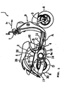
- Fig. 1 is a side view of a scooter-type motorcycle with the exhaust gas purifying device.
- Fig. 2 is a side view of an exhaust system of the motorcycle.
- Fig. 3 is a schematic view of the exhaust gas purifying device.
- Figs. 4 through 8 which will be described later, show in detail the exhaust gas purifying device for an engine in accordance with the first embodiment.
- reference numeral 1 denotes a scooter-type motorcycle.
- An underbone-type body frame 2 at its front end supports a front fork 3 to rotate leftward and rightward.
- the central portion of the body frame 2 supports a unit swing-type engine unit 4 to swing upward and downward.
- a seat 5 is mounted above the engine unit 4.
- the front fork 3 at its lower and upper ends is provided with a front wheel 6 and a steering handlebars 7, respectively.
- the engine unit 4 at its rear end is provided with a rear wheel 8.
- the front fork 3 is covered by a front cover 9, and the region under the seat 5 is covered by a rear cover 10.
- the region between the front cover 9 and the rear cover 10 is provided with a low-height footboard 11.
- the engine unit 4 has a unitized structure of a four-stroke, water-cooled engine, and a transmission case having a V-belt type continuously variable transmission.
- the engine is mounted with its cylinder axis oriented generally horizontally forward.
- Reference numeral 4a denotes a cooling air introduction opening.
- an intake system (not shown) having an intake pipe, a carburetor, and an air cleaner.
- an exhaust system 14 On the right side of the engine unit with respect to the moving direction of the vehicle is provided an exhaust system 14 having an exhaust pipe 15 and a silencer 30.
- the exhaust pipe 15 at its upstream end 15a extends rightward with respect to the moving direction of the vehicle from its engine connecting portion 15b, and rearward generally linearly.
- the silencer 30 is connected to a downstream end 15c of the exhaust pipe 15 to enclose it.
- the silencer 30 has a hollow body 32 as a cylindrical member having a generally oval shape in cross section and formed airtightly, the inside of which is defined into plural expansion chambers (sound-absorbing chambers) by partitions.
- a tail pipe 17 is connected to a rear-end expansion chamber with respect to the moving direction of the vehicle, and an opening of the downstream end 15c of the exhaust pipe 15 is positioned in another expansion chamber.
- the tail pipe 17 projects outside the silencer through a lid member 36 joined to the hollow body 32 at its rear opening with respect to the moving direction of the vehicle.
- a generally triangular bracket 18 is joined to the silencer 30 and the exhaust pipe 15, and fastened to the engine unit 4 with bolts.
- the exhaust system 14 thereby swings upward and downward along with the engine unit 4.
- the exhaust system 14 is provided with an exhaust gas purifying device 20 for purifying NOx, CO and HC in exhaust gas discharged from the engine.
- the exhaust gas purifying device 20 has an upstream-side catalyst 21 to mainly provide reducing function and a downstream-side catalyst 22 to mainly provide oxidizing function positioned in the exhaust pipe 15 with a predetermined distance between each other.
- the exhaust pipe 15 at its portion between the upstream-side catalyst 21 and the downstream-side catalyst 22 is connected to a secondary air supply pipe 23.
- the upstream-side catalyst 21 and the downstream-side catalyst 22 are positioned in the downstream end 15c accommodated in the hollow body 32 of the silencer 30.
- the downstream end 15c at its portion where the downstream-side catalyst 22 is located is formed to have a larger diameter than its other portions.
- the secondary air supply pipe 23 is welded to the downstream end 15c in the vicinity of and downstream from the upstream-side catalyst 21.
- the upstream-side catalyst 21, and the secondary air supply pipe 23 at its connected portion 23a to the exhaust pipe 15 are covered by the silencer 30, which functions as a heat insulating portion which encloses the outside of the upstream-side catalyst 21 and as a cover portion to cover the connected portion 23a.
- the secondary air supply pipe 23 having a curved portion 23c extends radially outward of the exhaust pipe 15 from the connected portion 23a and curves at its curved portion 23c and then extends in the same direction as the axial direction of the exhaust pipe 15.
- the secondary air supply pipe 23 then projects outside the silencer 30 through a through hole 34a formed in a lid member 34 which is joined to the hollow body 32 at its front opening with respect to the moving direction of the vehicle.
- An outside projecting portion 23b of the secondary air supply pipe 23 and the hollow body 32 are airtightly joined together by welding. Since the downstream end 15c of the exhaust pipe 15 and the secondary air supply pipe 23 extend in the same direction, they are identical in direction of thermal expansion. Therefore, the difference in expansion between the secondary air supply pipe 23 and the downstream end 15c of the exhaust pipe 15 is reduced, thereby preventing damage to the connected portion 23a of the secondary air supply pipe 23.
- the secondary air supply pipe 23 extends in a direction at right angles to the axis of the exhaust pipe 15, as indicated in Fig. 3 by the phantom lines, since the difference in temperature between the downstream end 15c and the hollow body 32 is large, the connected portion 23a is easily damaged by stress caused by the difference in thermal expansion between the downstream end 15c of the exhaust pipe 15 and the hollow body 32.
- the secondary air supply pipe 23 is joined by welding to the exhaust pipe 15, at its connected portion 23a, and also to the through hole 34a of the lid member 34, thereby increasing strength for supporting the secondary air supply pipe 23.
- the outside projecting portion 23b of the secondary air supply pipe 23 is connected to an end of a secondary air introduction pipe 25.
- the other end of the secondary air introduction pipe 25 is connected to a reed valve assembly 26.
- the reed valve assembly 26 is provided inside the rear cover 10 below the rear portion of the seat 5 and above the rear wheel 8 and has a function to permit the flow of secondary air toward the catalysts only and prevent its backflow. More specifically, secondary air is drawn in the exhaust pipe 15 through the reed valve assembly 26 by negative pressure produced in the exhaust pipe 15.
- the secondary air introduction pipe 25 is configured by a flexible pipe capable of absorbing upward and downward swinging motion of the engine unit 4.
- the reed valve assembly 26 may be positioned under the footboard 11 (A), or on the body frame 2 below the seat 5, at its raised portion (B), or at a crankcase of the engine unit 4 (C), or at the inner side of the bracket 18 (D), as shown in Fig. 1 . This allows minimizing the routing length of the secondary air introduction pipe 25.
- an air cleaner for the reed valve assembly 26 may be the one especially therefor disposed in the vicinity of and upstream from the assembly 26, or may be the one also used as the intake air cleaner for the engine.
- the upstream-side catalyst 21 and the downstream-side catalyst 22 are located with a distance therebetween in the downstream end 15c of the exhaust pipe 15 inserted in the hollow body 32 of the silencer 30, and the secondary air supply pipe 23 is connected between the upstream-side catalyst 21 and the downstream-side catalyst 22.
- the connected portion 23a of the secondary air supply pipe 23 can be covered by the silencer 30, thereby avoiding a poor appearance due to the connected portion 23a exposed to the outside.
- the existing silencer 30 can be effectively used as a heat insulating portion for the upstream-side catalyst 21 and also as a cover portion for the connected portion 23a.
- the silencer 30 alone can prevent damage caused by heat from the upstream-side catalyst 21, and exposure of the connected portion 23a to the outside, which requires no additional members to cover the upstream-side catalyst and the connected portion, so that increase in the number of parts can be prevented.
- the secondary air supply pipe 23 extends radially of the exhaust pipe 15 from its connected portion 23a to the exhaust pipe 15 and then curves at its curved portion 23c in the same direction as the axial direction of the exhaust pipe 15. Then, the secondary air supply pipe 23 further extends and projects to the outside from the lid member 34 joined to the front end of the hollow body 32, so that the exhaust pipe 15 and the secondary air supply pipe 23 are identical in direction of thermal expansion. This can prevent deformation of the secondary air supply pipe 23 and damage to the connected portion 23a caused by the difference in thermal expansion between the exhaust pipe 15 and the hollow body 32. Further, the secondary air supply pipe 23 is joined to the exhaust pipe 15 and the lid member 34 by welding, thereby increasing strength for supporting the secondary air supply pipe 23.
- Fig. 4 is a detailed sectional view of the exhaust gas purifying device in accordance with the first embodiment.
- the silencer 30 includes the hollow body 32, the front lid member 34 of a cup shape joined to the hollow body 32 at its front opening with respect to the moving direction of the vehicle, and the rear lid member 36 joined also to the hollow body at its rear opening with respect to the moving direction of the vehicle.
- the hollow body 32, the front lid member 34, and the rear lid member 36 each have a double structure.
- the gap between an outside member and an inside member of the hollow body 32 is filled with glass wool 32a, thereby increasing heat insulating properties of the silencer 30.
- the inside of the silencer 30 is defined by a first partition 38 and a second partition 40 into a first expansion chamber 50, a second expansion chamber 51, and a third expansion chamber 52 in that order from its rear side with respect to the moving direction of the vehicle.
- the front lid member 34 includes an outside wall member 61 of a cup shape configuring the outside wall of the silencer 30, and an inside wall member 30b of a cup shape accommodated inside the outside wall member 61 and configuring the inside wall of the silencer 30, and both these members are formed with through holes 34a.
- the exhaust pipe 15 extends longitudinally of the silencer 30 from the front side to the rear side with respect to the moving direction of the vehicle and is inserted in the through holes 34a, at its downstream end 15c, so that the entire downstream end 15c is accommodated inside the silencer 30.
- the inside of the downstream end 15c is provided with the two catalysts, the upstream-side catalyst 21 and the downstream-side catalyst 22.
- the upstream-side catalyst 21 and the downstream-side catalyst 22 are both provided inside the downstream end 15c to be located inside the silencer 30.
- the downstream end 15c is inserted through and supported by the first partition 38 and the second partition 40 inside the silencer 30.
- Exhaust gas supplied from the upstream side of the exhaust pipe 15 flows through the upstream-side catalyst 21. After flowing through the upstream-side catalyst 21, the exhaust gas is mixed with secondary air supplied from the secondary air supply pipe 23.
- the front lid member 34 is formed with a through hole 34b, which is different from the through hole 34a in which the downstream end 15c of the exhaust pipe 15 is inserted (see Fig. 6 ).
- the secondary air supply pipe 23 is inserted in the through hole 34b.
- the secondary air supply pipe 23 extends in the same direction as the axial direction of the downstream end 15c inside the silencer 30, curves toward the exhaust pipe 15, at its curved portion 23c, and connects to the exhaust pipe 15, at its end.
- the connected portion 23a of the secondary air supply pipe 23a to the downstream end 15c, and the exhaust pipe 15 downstream from the connected portion 23a are accommodated in the silencer 30. Therefore, a poor appearance due to the connected portion 23a exposed outside the silencer 30 can be avoided, and heat generated from the upstream-side catalyst 21 and the downstream-side catalyst 22 when they are activated can be kept in the silencer 30.
- Fig. 5 is a sectional view taken along the line V-V of Fig. 4 , mainly showing the secondary air supply pipe 23 and the downstream end 15c.
- the secondary air supply pipe 23 is introduced in the silencer 15 through the through hole 34b formed in the front lid member 34 closer to the vehicle body than the through hole 34a in which the silencer 15 is inserted (see Figs. 6 through 8 ), and then extends in the third expansion chamber 52 and the second expansion chamber 51 in the same direction as the axial direction of the downstream end 15c of the silencer 15, rearward from the front with respect to the moving direction of the vehicle (see Fig.
- the secondary air supply pipe 23 curves at its curved portion 23c toward the downstream end 15c, namely, to the outside of the vehicle and connects to the downstream end 15c of the exhaust pipe 15, at its end. More specifically, the end of the secondary air supply pipe 23 is joined to a secondary air inlet 15d formed in the downstream end 15c between the upstream-side catalyst 21 and the downstream-side catalyst 22. The secondary air inlet 15d is located in the second expansion chamber 51 of the silencer 30, as shown in Fig. 4 . The end of the secondary air supply pipe 23 is fitted in an annular reinforcing member 42.
- the reinforcing member 42 and the end of the secondary air supply pipe 23 are joined together by welding and also each joined to the side of the downstream end 15c, at the periphery of the secondary air inlet 15d by welding.
- strength for supporting the secondary air supply pipe 23 against the downstream end 15c is increased.
- the secondary air supply pipe 23 is inserted through and supported by the second partition 40. This prevents swinging motion of the secondary air supply pipe 23 in the silencer 30, thereby realizing the exhaust gas purifying device with good durability.
- the secondary air supply pipe 23 is made up of a first supply pipe portion 23d and a second supply pipe portion 23e connected to each other to permit the flow of secondary air.
- the secondary air supply pipe 23 joined to the downstream end 15c is the first supply pipe portion 23d which configures the secondary air supply pipe 23.
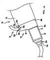
- Fig. 6 is a side view of the exhaust gas purifying device 20 at its front portion with respect to the moving direction of the vehicle.
- Fig. 7 is a sectional view taken along the line VII-VII of Fig. 6 .
- shown on the right side of the exhaust gas purifying device 20 is the rear wheel 8 of the vehicle.
- the through hole 34b in which the secondary air supply pipe 23 is inserted is formed closer to the vehicle body, namely, to the rear wheel 8 than the through hole 34a in which the exhaust pipe 15 is inserted.
- the secondary air supply pipe 23 is made up of the first supply pipe portion 23d extending inside and outside the silencer 30, and the second supply pipe portion 23e having the same diameter as the first supply pipe portion and connected to the first supply pipe portion 23d outside the silencer 30 to permit the flow of secondary air.
- the first supply pipe portion 23d is introduced inside the silencer 30 through the through hole 34b and then extends in the moving direction of the vehicle in parallel with the exhaust pipe 15 and connects to the exhaust pipe 15 between the upstream-side catalyst 21 and the downstream-side catalyst 22, as shown in Fig. 5 .
- the second supply pipe portion 23e extends in the moving direction of the vehicle by some length from its joint 23f to the first supply pipe portion 23d and then curves and extends obliquely upward.
- the second supply pipe portion 23e is fixed to the silencer 30 by a support member 37.
- the support member 37 is a plate-shaped member extending from the side of the second supply pipe portion 23e toward the front lid member 34.
- the support member at its one end is bend to form a mounting portion 37a, which is joined to the front lid member 34 by welding.
- the other end of the support member is curved along the side of the second supply pipe portion 23 to form a mounting portion 37b, which is joined to the outside surface of the second supply pipe portion 23e by welding.
- the second supply pipe portion 23e is thus supported by the silencer 30.
- a bracket 32b is joined to the upper part of the hollow body 32, and the exhaust gas purifying device 20 is mounted to the vehicle body by the bracket 32b.
- Fig. 8 is a partially sectional view, as seen from above, of the front side of the exhaust gas purifying device 20 with respect to the moving direction of the vehicle, showing the attached portion of the second supply pipe portion 23e to the first supply pipe portion 23d in section.
- the first supply pipe portion 23d at its outside periphery is joined by welding to a flange 60 formed at the peripheral edge of the through hole 34a of the outside wall member 61 of the front lid member 34, and a flange 62 formed at the peripheral edge of the through hole 34a of the inside wall member 63 of the front lid member.
- the first supply pipe portion 23d at its end outside the silencer 30 is joined to an end of the second supply pipe portion 23e.
- the lower end of the second supply pipe portion 23e is formed to have a larger diameter than its other portions, and receives the outside end of the first supply pipe portion 23d and is joined thereto by welding. Since the second supply pipe portion is supported by the support member 37 and also joined to the first supply pipe portion, at its joint 23f, by welding, it is securely supported against the exhaust gas purifying device 20.
- the connected portion 23a of the secondary air supply pipe 23 to the downstream end 15c of the exhaust pipe 15, and the exhaust pipe 15 downstream from the connected portion 23a are accommodated in the silencer 30.
- the upstream-side catalyst 21 and the downstream-side catalyst 22 are disposed in the exhaust pipe 15 and in the sound-absorbing chambers 15. This prevents heat from exhaust gas from spreading, so that time required for the temperature of the catalysts 21, 22 to reach their activation temperature is shortened.
- the secondary air supply pipe 23 extends through the third expansion chamber 52 and the second expansion chamber 51 and then connects to the exhaust pipe 15, secondary air slightly increases in temperature while it flows in the secondary air supply pipe 23. Therefore, the secondary air is mixed with exhaust gas after its temperature is increased, thereby preventing the temperature of the catalysts 21, 22 from being greatly reduced by the secondary air.
- the first supply pipe portion 23d of the secondary air supply pipe 23 is joined to the downstream end 15c of the exhaust pipe 15 at its secondary air inlet 15d to be integral therewith.
- the integrated members are accommodated in the silencer 30, and then the front opening of the cylindrical member 32 is covered by the front lid member 34 so that the silencer 30 can be unitized.
- the unitized silencer 30 can be mounted to the vehicle body in a way such that: the exhaust pipe 15 and the first supply pipe portion 23d extending from the front lid member 34 of the silencer 30 are each joined to the vehicle body, at its upstream side; and the bracket 32b and other mounting members are connected to the vehicle body.
- Fig. 9 is a sectional view of the exhaust gas purifying device in accordance with the second embodiment.
- Fig. 10 is a perspective view of the front portion of the exhaust gas purifying device 20 with respect to the moving direction of the vehicle.
- the inside of a silencer 30 has a first expansion chamber 50, a second expansion chamber 51 and a third expansion chamber formed in that order from the front side to the rear side of the vehicle.
- the rear end of an exhaust pipe 15 is curved accordingly in a U-shape, and its discharge opening is located in the first expansion chamber 50 which is located foremost in the silencer.
- a front lid member 34 is made up of an inside wall member 35, an outside wall member 39, and a cylindrical lid member 33.
- the outside wall member 39 is formed in a generally cup shape, and its bottom is formed with an introduction opening 39a for a downstream end 15c.
- the cylindrical lid member 33 is formed in a cylindrical shape and joined to the introduction opening 39a of the outside wall member 39, at its one end, and the exhaust pipe 15 is inserted in the cylindrical lid member 33.
- the inside of the cylindrical lid member 33 is provided with an upstream-side catalyst 21 disposed in the exhaust pipe 15.
- the other end of the cylindrical lid member 33 is formed as a tapered portion 33a, and the exhaust pipe 15 at its side is supported at the front end of the tapered portion 33a.
- the inside wall member 35 is also formed in a generally cup shape, and its bottom surface has a semi-circular bottom portion 35a which is deeper in depth than its other portions.
- the inside wall member 35 is fitted inside the outside wall member 39, and an edge 35c of the inside wall member is joined to the outside wall member 39 at the inner side of its edge 39c.
- the inside wall member 35 is also formed with a through hole 35d in which the downstream end 15c is inserted. Since the inside wall member 35 has the bottom portion 35a, the first expansion chamber 50 can be increased in capacity, thereby improving sound-absorbing performance of the silencer 30.
- a secondary air supply pipe 23 is connected to the downstream end 15c between the outside wall member 39 and the inside wall member 35 and downstream from the upstream-side catalyst 21. Now, description will be made of connection of the secondary air supply pipe 23 to the downstream end 15c, with further reference to Fig. 11.
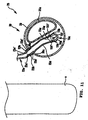
- Fig. 11 is a sectional view taken along the line XI-XI of Fig. 9 . In Fig. 11 , a rear wheel 8 of the vehicle is indicated on the left side of the exhaust gas purifying device.
- the secondary air supply pipe 23 is introduced inside the silencer 30 through the side of the silencer 30 close to the vehicle body.
- the outside wall member 39 at its upper side close to the vehicle body is formed with a through hole 39c, through which the secondary air supply pipe 23 is inserted inside the silencer 30.
- the bottom portion 35a of the inside wall member 35 is shown in a semi-circular shape in section.
- the secondary air supply pipe 23 is introduced inside the silencer 30 from outside along the side of the bottom portion 35a of the inside wall member 35. Then, an end 23g of the secondary air supply pipe 23 is connected to the downstream end 15c provided in the silencer 30 along its bottom.
- the secondary air supply pipe 23 is made up of a first supply pipe portion 23d and a second supply pipe portion 23e.
- the downstream end 15c is formed with a secondary air inlet 15f, and the one end 23g of the first supply pipe portion 23d and the peripheral edge of the secondary air inlet 15f are joined together by welding. More specifically, as indicated in Figs. 9 and 11 , the downstream end 15c in the proximity of the secondary air inlet 15f is made up of a semi-cylindrical lower surface 15g configuring the lower side of the downstream end 15c and formed in a generally semi-cylindrical shape, and a semi-cylindrical upper surface 15h configuring the upper side of the downstream end 15c and also formed in a generally semi-cylindrical shape.
- the semi-cylindrical lower surface 15g at its outside peripheral surface and the semi-cylindrical upper surface 15h at its inside peripheral surface are joined together to form the cylindrical downstream end 15c as a whole.
- the secondary air inlet 15f is formed in the semi-cylindrical upper surface 15h, and the edge of the secondary air inlet 15f is formed as a flange 15f'.
- the flange 15f' and the one end 23g of the first supply pipe portion 23d are joined together by welding.
- the first supply pipe portion 23d at its outside periphery 23d' is joined to the edge of the through hole 39c formed in the outside wall member 39. Then, the first supply pipe portion 23d at its other end 23h and the second supply pipe portion 23e are connected together.
- the other end 23h of the first supply pipe portion 23d is formed to have a larger diameter than its other portions and receives an end of the second supply pipe portion 23e. Then, the second supply pipe portion 23e at its outside periphery 23e' and the other end 23h of the first supply pipe portion 23d are joined together outside the silencer 30 by welding. In such manner, the outside wall member 39 having high temperature, and the first supply pipe portion 23d also having high temperature are joined together. Meanwhile, the outside periphery 23e' of the second supply pipe portion 23e and the other end 23h of the first supply pipe portion 23d, each having low temperature since they are located outside the silencer 30, are joined together. Thus, the portions having a small temperature difference are joined together, thereby increasing reliability of each joint.
- the secondary air supply pipe 23 is connected to the exhaust pipe 15 outside the inside wall member 35.
- the exhaust pipe 15 at its downstream end 15c downstream from the connected portion 23a is introduced in a cylindrical body formed by the inside wall member 35, a hollow body 32, and a rear lid member 36 through the through hole 35d formed in the inside wall member 35.
- the connected portion 23a of the secondary air supply pipe 23 to the downstream end 15c is covered by the outside wall member 39. This avoids a poor appearance due to the joint 23a exposed to the outside. Further, since a downstream-side catalyst 22 is accommodated in the cylindrical body of the silencer 30, heat generated from the catalyst 22 when it is activated is kept inside.
- the rear end of the downstream end 15c is disposed inside the first expansion chamber 50 provided inside the silencer 30 at its front side with respect to the moving direction of the vehicle, and exhaust gas having high temperature directly contacts the inside wall member 35 which faces the rear end of the downstream end 15c, as shown in Fig. 9 .
- the secondary air supply pipe 23 and the downstream end 15c are connected together outside the inside wall member 35, the secondary air supply pipe 23 can be prevented from being excessively heated.
- the first supply pipe portion 23d is introduced inside the silencer 30 through the through hole 39c formed in the outside wall member 39.
- FIG. 12 is an explanatory view of an exhaust gas purifying device in accordance with a third embodiment of the present invention, in which similar parts are denoted by the same reference numerals as in Fig. 3 .
- This embodiment is configured such that: an upstream-side catalyst 21 is positioned in an exhaust pipe 15 outside a silencer 30; a downstream-side catalyst 22 is located in the silencer 30; a connected portion 23a of a secondary air supply pipe 23 is covered by the silencer 30; and the exhaust pipe 15 at the periphery of its portion where the upstream-side catalyst 21 is located is enclosed by a heat protector 60, which functions as a heat insulating portion.
- the connected portion 23a of the secondary air supply pipe 23 is covered by the silencer 30 as a cover member, a poor appearance due to the connected portion 23a exposed to the outside can be avoided. Further, since the upstream-side catalyst 21 is enclosed by the existing heat protector 60, effect caused by heat, as well as a poor look can be prevented without cost increase.
- the present invention is not limited to the embodiments described above but may be modified in various ways.
- the single exhaust pipe 15 is connected to the engine.
- this may be modified in a way such that a plurality of exhaust pipes are connected to the engine and each introduced inside the silencer 30.
- a plurality of exhaust pipes connected to the engine may be collected together upstream from the silencer 30 into a single pipe, which is then introduced in the silencer 30.
- the two catalysts, the upstream-side catalyst 21 and the downstream-side catalyst 22 are provided in the exhaust pipe 15, but only a single catalyst may be provided therein.
- the embodiments provide an exhaust gas purifying device (20) for a straddle-type vehicle, including:
Landscapes
- Engineering & Computer Science (AREA)
- Chemical & Material Sciences (AREA)
- Combustion & Propulsion (AREA)
- Chemical Kinetics & Catalysis (AREA)
- Mechanical Engineering (AREA)
- General Engineering & Computer Science (AREA)
- Health & Medical Sciences (AREA)
- Biomedical Technology (AREA)
- Toxicology (AREA)
- Environmental & Geological Engineering (AREA)
- Analytical Chemistry (AREA)
- General Chemical & Material Sciences (AREA)
- Oil, Petroleum & Natural Gas (AREA)
- Exhaust Gas After Treatment (AREA)
- Exhaust Silencers (AREA)
- Steering Control In Accordance With Driving Conditions (AREA)
- Control Of Direct Current Motors (AREA)
- Control Of Electric Motors In General (AREA)
Applications Claiming Priority (2)
| Application Number | Priority Date | Filing Date | Title |
|---|---|---|---|
| JP2004047399 | 2004-02-24 | ||
| EP05710664A EP1722079B1 (de) | 2004-02-24 | 2005-02-24 | Abgasreinigungsvorrichtung für einen motor |
Related Parent Applications (1)
| Application Number | Title | Priority Date | Filing Date |
|---|---|---|---|
| EP05710664.3 Division | 2005-02-24 |
Publications (2)
| Publication Number | Publication Date |
|---|---|
| EP2159391A1 true EP2159391A1 (de) | 2010-03-03 |
| EP2159391B1 EP2159391B1 (de) | 2011-06-15 |
Family
ID=34879474
Family Applications (4)
| Application Number | Title | Priority Date | Filing Date |
|---|---|---|---|
| EP05710664A Expired - Lifetime EP1722079B1 (de) | 2004-02-24 | 2005-02-24 | Abgasreinigungsvorrichtung für einen motor |
| EP08020448A Expired - Lifetime EP2050937B1 (de) | 2004-02-24 | 2005-02-24 | Abgasreinigungsvorrichtung für einen Motor |
| EP09014238A Expired - Lifetime EP2159391B1 (de) | 2004-02-24 | 2005-02-24 | Abgasreinigungsvorrichtung für einen Motor |
| EP09014237A Expired - Lifetime EP2159390B1 (de) | 2004-02-24 | 2005-02-24 | Abgasreinigungsvorrichtung für einen Motor |
Family Applications Before (2)
| Application Number | Title | Priority Date | Filing Date |
|---|---|---|---|
| EP05710664A Expired - Lifetime EP1722079B1 (de) | 2004-02-24 | 2005-02-24 | Abgasreinigungsvorrichtung für einen motor |
| EP08020448A Expired - Lifetime EP2050937B1 (de) | 2004-02-24 | 2005-02-24 | Abgasreinigungsvorrichtung für einen Motor |
Family Applications After (1)
| Application Number | Title | Priority Date | Filing Date |
|---|---|---|---|
| EP09014237A Expired - Lifetime EP2159390B1 (de) | 2004-02-24 | 2005-02-24 | Abgasreinigungsvorrichtung für einen Motor |
Country Status (8)
| Country | Link |
|---|---|
| EP (4) | EP1722079B1 (de) |
| JP (1) | JP4365859B2 (de) |
| CN (2) | CN101832169B (de) |
| AT (3) | ATE505630T1 (de) |
| DE (1) | DE602005027509D1 (de) |
| ES (3) | ES2365184T3 (de) |
| TW (1) | TW200530493A (de) |
| WO (1) | WO2005080764A1 (de) |
Families Citing this family (14)
| Publication number | Priority date | Publication date | Assignee | Title |
|---|---|---|---|---|
| JP2007040249A (ja) * | 2005-08-04 | 2007-02-15 | Yamaha Motor Co Ltd | 排気ガス浄化機能を有するエンジン及び車両 |
| JP2007092564A (ja) * | 2005-09-27 | 2007-04-12 | Toyota Motor Corp | 車両用排気構造 |
| JP2007297984A (ja) * | 2006-05-01 | 2007-11-15 | Yamaha Motor Co Ltd | 排気装置およびその排気装置を備えた車両 |
| JP2007297985A (ja) * | 2006-05-01 | 2007-11-15 | Yamaha Motor Co Ltd | 排気装置およびその排気装置を備えた車両 |
| JP4871107B2 (ja) * | 2006-12-06 | 2012-02-08 | ヤマハ発動機株式会社 | 鞍乗り型車両 |
| JP4988326B2 (ja) | 2006-12-20 | 2012-08-01 | ヤマハ発動機株式会社 | 自動二輪車用4サイクルエンジンの排気装置 |
| WO2008149777A1 (ja) * | 2007-05-30 | 2008-12-11 | Yamaha Hatsudoki Kabushiki Kaisha | 排気装置、及び鞍乗型車両 |
| WO2009041028A1 (ja) * | 2007-09-27 | 2009-04-02 | Yamaha Hatsudoki Kabushiki Kaisha | 鞍乗り型車両 |
| JP5022264B2 (ja) * | 2008-02-15 | 2012-09-12 | 本田技研工業株式会社 | 自動二輪車 |
| GR20080100358A (el) * | 2008-05-27 | 2009-12-31 | Honda Motor Co., Ltd. | Συστημα εξατμισης μοτοσικλετας |
| CN102359412B (zh) * | 2011-09-23 | 2015-09-23 | 江门市大长江集团有限公司 | 防逆流摩托车排气装置 |
| JP7095279B2 (ja) * | 2017-12-27 | 2022-07-05 | トヨタ自動車株式会社 | 車両の排気装置 |
| DE102021119169B4 (de) | 2021-07-23 | 2024-06-13 | Tenneco Gmbh | Abgasteilanlage |
| JP2023064376A (ja) * | 2021-10-26 | 2023-05-11 | ヤマハ発動機株式会社 | スクータ型車両 |
Citations (5)
| Publication number | Priority date | Publication date | Assignee | Title |
|---|---|---|---|---|
| US4048092A (en) * | 1973-03-05 | 1977-09-13 | Colonial Metals, Inc. | Catalytic mixture and method of use therefor |
| EP0356607A1 (de) * | 1988-08-19 | 1990-03-07 | Ap Parts Manufacturing Company | Durch Stanzverfahren hergestellter Schalldämpfer und katalytische Konvertereinheit |
| JP2504008Y2 (ja) | 1990-06-26 | 1996-07-03 | 本田技研工業株式会社 | エンジンの排気浄化装置 |
| US5897843A (en) * | 1994-11-07 | 1999-04-27 | Honda Giken Kogyo Kabushiki Kaisha | Exhaust gas purifier |
| FR2827908A1 (fr) * | 2001-07-26 | 2003-01-31 | Peugeot Motocycles Sa | Systeme de purification des gaz d'echappement d'un moteur thermique a deux temps, notamment pour vehicule a deux roues |
Family Cites Families (10)
| Publication number | Priority date | Publication date | Assignee | Title |
|---|---|---|---|---|
| US3773894A (en) * | 1971-07-22 | 1973-11-20 | Exxon | Nitrogen oxide conversion using reinforced nickel-copper catalysts |
| JPS4843012U (de) * | 1971-09-27 | 1973-06-02 | ||
| JPS493013A (de) * | 1972-04-28 | 1974-01-11 | ||
| JPS6043111U (ja) * | 1983-08-31 | 1985-03-27 | 株式会社 土屋製作所 | 内燃機関用触媒マフラ−装置 |
| US4830833A (en) * | 1986-06-12 | 1989-05-16 | Echlin Incorporated | Catalytic converter |
| JPH04140413A (ja) * | 1990-10-01 | 1992-05-14 | Yamaha Motor Co Ltd | 内燃機関の排気ガス浄化装置 |
| JPH05118257A (ja) * | 1991-10-24 | 1993-05-14 | Honda Motor Co Ltd | エンジンにおける燃料蒸気処理装置 |
| JP3932439B2 (ja) * | 1997-04-24 | 2007-06-20 | 本田技研工業株式会社 | 小型自動二輪車の排気系への2次空気供給装置 |
| JP4145983B2 (ja) * | 1998-02-18 | 2008-09-03 | 三菱重工業株式会社 | エンジンの2次空気供給装置 |
| CN2463543Y (zh) * | 2001-02-12 | 2001-12-05 | 郑巍 | 摩托车三元催化转化排气消声器 |
-
2005
- 2005-02-24 ES ES08020448T patent/ES2365184T3/es not_active Expired - Lifetime
- 2005-02-24 EP EP05710664A patent/EP1722079B1/de not_active Expired - Lifetime
- 2005-02-24 ES ES09014238T patent/ES2365197T3/es not_active Expired - Lifetime
- 2005-02-24 EP EP08020448A patent/EP2050937B1/de not_active Expired - Lifetime
- 2005-02-24 AT AT09014237T patent/ATE505630T1/de not_active IP Right Cessation
- 2005-02-24 AT AT09014238T patent/ATE513120T1/de not_active IP Right Cessation
- 2005-02-24 WO PCT/JP2005/003063 patent/WO2005080764A1/ja not_active Ceased
- 2005-02-24 CN CN2010101588830A patent/CN101832169B/zh not_active Expired - Fee Related
- 2005-02-24 AT AT08020448T patent/ATE513121T1/de not_active IP Right Cessation
- 2005-02-24 TW TW094105624A patent/TW200530493A/zh not_active IP Right Cessation
- 2005-02-24 DE DE602005027509T patent/DE602005027509D1/de not_active Expired - Lifetime
- 2005-02-24 JP JP2006510317A patent/JP4365859B2/ja not_active Expired - Fee Related
- 2005-02-24 EP EP09014238A patent/EP2159391B1/de not_active Expired - Lifetime
- 2005-02-24 EP EP09014237A patent/EP2159390B1/de not_active Expired - Lifetime
- 2005-02-24 ES ES05710664T patent/ES2396235T3/es not_active Expired - Lifetime
- 2005-02-24 CN CN2005800055003A patent/CN1922392B/zh not_active Expired - Fee Related
Patent Citations (5)
| Publication number | Priority date | Publication date | Assignee | Title |
|---|---|---|---|---|
| US4048092A (en) * | 1973-03-05 | 1977-09-13 | Colonial Metals, Inc. | Catalytic mixture and method of use therefor |
| EP0356607A1 (de) * | 1988-08-19 | 1990-03-07 | Ap Parts Manufacturing Company | Durch Stanzverfahren hergestellter Schalldämpfer und katalytische Konvertereinheit |
| JP2504008Y2 (ja) | 1990-06-26 | 1996-07-03 | 本田技研工業株式会社 | エンジンの排気浄化装置 |
| US5897843A (en) * | 1994-11-07 | 1999-04-27 | Honda Giken Kogyo Kabushiki Kaisha | Exhaust gas purifier |
| FR2827908A1 (fr) * | 2001-07-26 | 2003-01-31 | Peugeot Motocycles Sa | Systeme de purification des gaz d'echappement d'un moteur thermique a deux temps, notamment pour vehicule a deux roues |
Also Published As
| Publication number | Publication date |
|---|---|
| EP2159390B1 (de) | 2011-04-13 |
| ES2396235T3 (es) | 2013-02-20 |
| ATE505630T1 (de) | 2011-04-15 |
| ES2365197T3 (es) | 2011-09-26 |
| EP1722079B1 (de) | 2012-11-21 |
| CN101832169A (zh) | 2010-09-15 |
| ATE513121T1 (de) | 2011-07-15 |
| EP2050937A1 (de) | 2009-04-22 |
| WO2005080764A1 (ja) | 2005-09-01 |
| TW200530493A (en) | 2005-09-16 |
| CN1922392A (zh) | 2007-02-28 |
| EP1722079A4 (de) | 2009-04-15 |
| TWI306132B (de) | 2009-02-11 |
| EP2159391B1 (de) | 2011-06-15 |
| CN1922392B (zh) | 2010-05-26 |
| EP2159390A1 (de) | 2010-03-03 |
| EP1722079A1 (de) | 2006-11-15 |
| ES2365184T3 (es) | 2011-09-26 |
| JPWO2005080764A1 (ja) | 2007-10-25 |
| DE602005027509D1 (de) | 2011-05-26 |
| EP2050937B1 (de) | 2011-06-15 |
| JP4365859B2 (ja) | 2009-11-18 |
| ATE513120T1 (de) | 2011-07-15 |
| CN101832169B (zh) | 2012-06-13 |
Similar Documents
| Publication | Publication Date | Title |
|---|---|---|
| US7624842B2 (en) | Exhaust system for an engine and motorcycle including the exhaust system | |
| EP3431726B1 (de) | Abgasvorrichtung für verbrennungsmotor | |
| EP2159390B1 (de) | Abgasreinigungsvorrichtung für einen Motor | |
| US8091349B2 (en) | Motorcycle | |
| CN101240730A (zh) | 机动二轮车的催化剂配置构造 | |
| JP7155860B2 (ja) | 鞍乗型車両の消音器構造 | |
| JP2007040249A (ja) | 排気ガス浄化機能を有するエンジン及び車両 | |
| US7677357B2 (en) | Muffler and vehicle equipped with muffler | |
| CN100400812C (zh) | 具有排气净化功能的发动机 | |
| US7866442B2 (en) | Muffler and vehicle equipped with muffler | |
| JP4696844B2 (ja) | 自動二輪車 | |
| JP3146202U (ja) | 排気ガス浄化装置 | |
| EP1703099B1 (de) | Abgasreinigungsvorrichtung | |
| JP2001012239A (ja) | エンジンの排気浄化器 | |
| JP6720326B2 (ja) | 鞍乗型車両の排気装置 | |
| JP2019210864A (ja) | 鞍乗型車両のテールパイプ構造 | |
| EP1703098B1 (de) | Abgasreinigungsvorrichtung | |
| JPH04287821A (ja) | 自動二輪車等の排気浄化装置 | |
| US20200123945A1 (en) | Muffler structure of saddle-type vehicle | |
| JPWO2018180272A1 (ja) | 鞍乗型車両の排気装置 |
Legal Events
| Date | Code | Title | Description |
|---|---|---|---|
| PUAI | Public reference made under article 153(3) epc to a published international application that has entered the european phase |
Free format text: ORIGINAL CODE: 0009012 |
|
| 17P | Request for examination filed |
Effective date: 20091113 |
|
| AC | Divisional application: reference to earlier application |
Ref document number: 1722079 Country of ref document: EP Kind code of ref document: P |
|
| AK | Designated contracting states |
Kind code of ref document: A1 Designated state(s): AT BE BG CH CY CZ DE DK EE ES FI FR GB GR HU IE IS IT LI LT LU MC NL PL PT RO SE SI SK TR |
|
| GRAP | Despatch of communication of intention to grant a patent |
Free format text: ORIGINAL CODE: EPIDOSNIGR1 |
|
| RIC1 | Information provided on ipc code assigned before grant |
Ipc: F01N 13/14 20100101ALI20110125BHEP Ipc: F01N 1/00 20060101ALI20110125BHEP Ipc: B62M 7/02 20060101ALI20110125BHEP Ipc: B01D 53/94 20060101ALI20110125BHEP Ipc: F01N 3/24 20060101ALI20110125BHEP Ipc: F01N 3/30 20060101AFI20110125BHEP Ipc: F01N 13/08 20100101ALI20110125BHEP |
|
| GRAS | Grant fee paid |
Free format text: ORIGINAL CODE: EPIDOSNIGR3 |
|
| GRAA | (expected) grant |
Free format text: ORIGINAL CODE: 0009210 |
|
| AC | Divisional application: reference to earlier application |
Ref document number: 1722079 Country of ref document: EP Kind code of ref document: P |
|
| AK | Designated contracting states |
Kind code of ref document: B1 Designated state(s): AT BE BG CH CY CZ DE DK EE ES FI FR GB GR HU IE IS IT LI LT LU MC NL PL PT RO SE SI SK TR |
|
| REG | Reference to a national code |
Ref country code: GB Ref legal event code: FG4D Ref country code: CH Ref legal event code: EP |
|
| REG | Reference to a national code |
Ref country code: IE Ref legal event code: FG4D |
|
| REG | Reference to a national code |
Ref country code: DE Ref legal event code: R096 Ref document number: 602005028596 Country of ref document: DE Effective date: 20110728 |
|
| REG | Reference to a national code |
Ref country code: GR Ref legal event code: EP Ref document number: 20110401705 Country of ref document: GR Effective date: 20110829 |
|
| REG | Reference to a national code |
Ref country code: ES Ref legal event code: FG2A Ref document number: 2365197 Country of ref document: ES Kind code of ref document: T3 Effective date: 20110926 |
|
| REG | Reference to a national code |
Ref country code: NL Ref legal event code: VDEP Effective date: 20110615 |
|
| PG25 | Lapsed in a contracting state [announced via postgrant information from national office to epo] |
Ref country code: LT Free format text: LAPSE BECAUSE OF FAILURE TO SUBMIT A TRANSLATION OF THE DESCRIPTION OR TO PAY THE FEE WITHIN THE PRESCRIBED TIME-LIMIT Effective date: 20110615 Ref country code: SE Free format text: LAPSE BECAUSE OF FAILURE TO SUBMIT A TRANSLATION OF THE DESCRIPTION OR TO PAY THE FEE WITHIN THE PRESCRIBED TIME-LIMIT Effective date: 20110615 |
|
| PG25 | Lapsed in a contracting state [announced via postgrant information from national office to epo] |
Ref country code: SI Free format text: LAPSE BECAUSE OF FAILURE TO SUBMIT A TRANSLATION OF THE DESCRIPTION OR TO PAY THE FEE WITHIN THE PRESCRIBED TIME-LIMIT Effective date: 20110615 Ref country code: FI Free format text: LAPSE BECAUSE OF FAILURE TO SUBMIT A TRANSLATION OF THE DESCRIPTION OR TO PAY THE FEE WITHIN THE PRESCRIBED TIME-LIMIT Effective date: 20110615 Ref country code: AT Free format text: LAPSE BECAUSE OF FAILURE TO SUBMIT A TRANSLATION OF THE DESCRIPTION OR TO PAY THE FEE WITHIN THE PRESCRIBED TIME-LIMIT Effective date: 20110615 Ref country code: CY Free format text: LAPSE BECAUSE OF FAILURE TO SUBMIT A TRANSLATION OF THE DESCRIPTION OR TO PAY THE FEE WITHIN THE PRESCRIBED TIME-LIMIT Effective date: 20110615 |
|
| PG25 | Lapsed in a contracting state [announced via postgrant information from national office to epo] |
Ref country code: BE Free format text: LAPSE BECAUSE OF FAILURE TO SUBMIT A TRANSLATION OF THE DESCRIPTION OR TO PAY THE FEE WITHIN THE PRESCRIBED TIME-LIMIT Effective date: 20110615 Ref country code: NL Free format text: LAPSE BECAUSE OF FAILURE TO SUBMIT A TRANSLATION OF THE DESCRIPTION OR TO PAY THE FEE WITHIN THE PRESCRIBED TIME-LIMIT Effective date: 20110615 |
|
| PG25 | Lapsed in a contracting state [announced via postgrant information from national office to epo] |
Ref country code: PT Free format text: LAPSE BECAUSE OF FAILURE TO SUBMIT A TRANSLATION OF THE DESCRIPTION OR TO PAY THE FEE WITHIN THE PRESCRIBED TIME-LIMIT Effective date: 20111017 Ref country code: IS Free format text: LAPSE BECAUSE OF FAILURE TO SUBMIT A TRANSLATION OF THE DESCRIPTION OR TO PAY THE FEE WITHIN THE PRESCRIBED TIME-LIMIT Effective date: 20111015 Ref country code: CZ Free format text: LAPSE BECAUSE OF FAILURE TO SUBMIT A TRANSLATION OF THE DESCRIPTION OR TO PAY THE FEE WITHIN THE PRESCRIBED TIME-LIMIT Effective date: 20110615 Ref country code: EE Free format text: LAPSE BECAUSE OF FAILURE TO SUBMIT A TRANSLATION OF THE DESCRIPTION OR TO PAY THE FEE WITHIN THE PRESCRIBED TIME-LIMIT Effective date: 20110615 |
|
| PG25 | Lapsed in a contracting state [announced via postgrant information from national office to epo] |
Ref country code: PL Free format text: LAPSE BECAUSE OF FAILURE TO SUBMIT A TRANSLATION OF THE DESCRIPTION OR TO PAY THE FEE WITHIN THE PRESCRIBED TIME-LIMIT Effective date: 20110615 Ref country code: SK Free format text: LAPSE BECAUSE OF FAILURE TO SUBMIT A TRANSLATION OF THE DESCRIPTION OR TO PAY THE FEE WITHIN THE PRESCRIBED TIME-LIMIT Effective date: 20110615 Ref country code: RO Free format text: LAPSE BECAUSE OF FAILURE TO SUBMIT A TRANSLATION OF THE DESCRIPTION OR TO PAY THE FEE WITHIN THE PRESCRIBED TIME-LIMIT Effective date: 20110615 |
|
| PLBE | No opposition filed within time limit |
Free format text: ORIGINAL CODE: 0009261 |
|
| STAA | Information on the status of an ep patent application or granted ep patent |
Free format text: STATUS: NO OPPOSITION FILED WITHIN TIME LIMIT |
|
| 26N | No opposition filed |
Effective date: 20120316 |
|
| PG25 | Lapsed in a contracting state [announced via postgrant information from national office to epo] |
Ref country code: DK Free format text: LAPSE BECAUSE OF FAILURE TO SUBMIT A TRANSLATION OF THE DESCRIPTION OR TO PAY THE FEE WITHIN THE PRESCRIBED TIME-LIMIT Effective date: 20110615 |
|
| REG | Reference to a national code |
Ref country code: DE Ref legal event code: R097 Ref document number: 602005028596 Country of ref document: DE Effective date: 20120316 |
|
| PG25 | Lapsed in a contracting state [announced via postgrant information from national office to epo] |
Ref country code: MC Free format text: LAPSE BECAUSE OF NON-PAYMENT OF DUE FEES Effective date: 20120229 |
|
| REG | Reference to a national code |
Ref country code: CH Ref legal event code: PL |
|
| GBPC | Gb: european patent ceased through non-payment of renewal fee |
Effective date: 20120224 |
|
| PG25 | Lapsed in a contracting state [announced via postgrant information from national office to epo] |
Ref country code: LI Free format text: LAPSE BECAUSE OF NON-PAYMENT OF DUE FEES Effective date: 20120229 Ref country code: CH Free format text: LAPSE BECAUSE OF NON-PAYMENT OF DUE FEES Effective date: 20120229 |
|
| REG | Reference to a national code |
Ref country code: IE Ref legal event code: MM4A |
|
| REG | Reference to a national code |
Ref country code: FR Ref legal event code: ST Effective date: 20121031 |
|
| REG | Reference to a national code |
Ref country code: DE Ref legal event code: R119 Ref document number: 602005028596 Country of ref document: DE Effective date: 20120901 |
|
| PG25 | Lapsed in a contracting state [announced via postgrant information from national office to epo] |
Ref country code: IE Free format text: LAPSE BECAUSE OF NON-PAYMENT OF DUE FEES Effective date: 20120224 Ref country code: FR Free format text: LAPSE BECAUSE OF NON-PAYMENT OF DUE FEES Effective date: 20120229 Ref country code: GB Free format text: LAPSE BECAUSE OF NON-PAYMENT OF DUE FEES Effective date: 20120224 |
|
| PG25 | Lapsed in a contracting state [announced via postgrant information from national office to epo] |
Ref country code: BG Free format text: LAPSE BECAUSE OF FAILURE TO SUBMIT A TRANSLATION OF THE DESCRIPTION OR TO PAY THE FEE WITHIN THE PRESCRIBED TIME-LIMIT Effective date: 20110915 Ref country code: DE Free format text: LAPSE BECAUSE OF NON-PAYMENT OF DUE FEES Effective date: 20120901 |
|
| PG25 | Lapsed in a contracting state [announced via postgrant information from national office to epo] |
Ref country code: LU Free format text: LAPSE BECAUSE OF NON-PAYMENT OF DUE FEES Effective date: 20120224 |
|
| PG25 | Lapsed in a contracting state [announced via postgrant information from national office to epo] |
Ref country code: HU Free format text: LAPSE BECAUSE OF FAILURE TO SUBMIT A TRANSLATION OF THE DESCRIPTION OR TO PAY THE FEE WITHIN THE PRESCRIBED TIME-LIMIT Effective date: 20050224 |
|
| PGFP | Annual fee paid to national office [announced via postgrant information from national office to epo] |
Ref country code: TR Payment date: 20220218 Year of fee payment: 18 Ref country code: IT Payment date: 20220218 Year of fee payment: 18 Ref country code: GR Payment date: 20220221 Year of fee payment: 18 |
|
| PGFP | Annual fee paid to national office [announced via postgrant information from national office to epo] |
Ref country code: ES Payment date: 20220426 Year of fee payment: 18 |
|
| PG25 | Lapsed in a contracting state [announced via postgrant information from national office to epo] |
Ref country code: GR Free format text: LAPSE BECAUSE OF NON-PAYMENT OF DUE FEES Effective date: 20230906 |
|
| PG25 | Lapsed in a contracting state [announced via postgrant information from national office to epo] |
Ref country code: IT Free format text: LAPSE BECAUSE OF NON-PAYMENT OF DUE FEES Effective date: 20230224 |
|
| REG | Reference to a national code |
Ref country code: ES Ref legal event code: FD2A Effective date: 20240404 |
|
| PG25 | Lapsed in a contracting state [announced via postgrant information from national office to epo] |
Ref country code: ES Free format text: LAPSE BECAUSE OF NON-PAYMENT OF DUE FEES Effective date: 20230225 |
|
| PG25 | Lapsed in a contracting state [announced via postgrant information from national office to epo] |
Ref country code: ES Free format text: LAPSE BECAUSE OF NON-PAYMENT OF DUE FEES Effective date: 20230225 |