EP2159432A2 - Coulisseau - Google Patents
Coulisseau Download PDFInfo
- Publication number
- EP2159432A2 EP2159432A2 EP09168071A EP09168071A EP2159432A2 EP 2159432 A2 EP2159432 A2 EP 2159432A2 EP 09168071 A EP09168071 A EP 09168071A EP 09168071 A EP09168071 A EP 09168071A EP 2159432 A2 EP2159432 A2 EP 2159432A2
- Authority
- EP
- European Patent Office
- Prior art keywords
- sliding block
- component
- mounting
- groove
- nut
- Prior art date
- Legal status (The legal status is an assumption and is not a legal conclusion. Google has not performed a legal analysis and makes no representation as to the accuracy of the status listed.)
- Withdrawn
Links
Images




Classifications
-
- F—MECHANICAL ENGINEERING; LIGHTING; HEATING; WEAPONS; BLASTING
- F16—ENGINEERING ELEMENTS AND UNITS; GENERAL MEASURES FOR PRODUCING AND MAINTAINING EFFECTIVE FUNCTIONING OF MACHINES OR INSTALLATIONS; THERMAL INSULATION IN GENERAL
- F16B—DEVICES FOR FASTENING OR SECURING CONSTRUCTIONAL ELEMENTS OR MACHINE PARTS TOGETHER, e.g. NAILS, BOLTS, CIRCLIPS, CLAMPS, CLIPS OR WEDGES; JOINTS OR JOINTING
- F16B37/00—Nuts or like thread-engaging members
- F16B37/04—Devices for fastening nuts to surfaces, e.g. sheets, plates
- F16B37/045—Devices for fastening nuts to surfaces, e.g. sheets, plates specially adapted for fastening in channels, e.g. sliding bolts, channel nuts
-
- E—FIXED CONSTRUCTIONS
- E05—LOCKS; KEYS; WINDOW OR DOOR FITTINGS; SAFES
- E05D—HINGES OR SUSPENSION DEVICES FOR DOORS, WINDOWS OR WINGS
- E05D15/00—Suspension arrangements for wings
- E05D15/48—Suspension arrangements for wings allowing alternative movements
- E05D15/52—Suspension arrangements for wings allowing alternative movements for opening about a vertical as well as a horizontal axis
- E05D15/5214—Corner supports
-
- E—FIXED CONSTRUCTIONS
- E05—LOCKS; KEYS; WINDOW OR DOOR FITTINGS; SAFES
- E05B—LOCKS; ACCESSORIES THEREFOR; HANDCUFFS
- E05B9/00—Lock casings or latch-mechanism casings ; Fastening locks or fasteners or parts thereof to the wing
- E05B9/08—Fastening locks or fasteners or parts thereof, e.g. the casings of latch-bolt locks or cylinder locks to the wing
-
- E—FIXED CONSTRUCTIONS
- E05—LOCKS; KEYS; WINDOW OR DOOR FITTINGS; SAFES
- E05D—HINGES OR SUSPENSION DEVICES FOR DOORS, WINDOWS OR WINGS
- E05D5/00—Construction of single parts, e.g. the parts for attachment
- E05D5/02—Parts for attachment, e.g. flaps
- E05D5/0215—Parts for attachment, e.g. flaps for attachment to profile members or the like
- E05D5/0223—Parts for attachment, e.g. flaps for attachment to profile members or the like with parts, e.g. screws, extending through the profile wall or engaging profile grooves
- E05D5/0238—Parts for attachment, e.g. flaps for attachment to profile members or the like with parts, e.g. screws, extending through the profile wall or engaging profile grooves with parts engaging profile grooves
-
- E—FIXED CONSTRUCTIONS
- E05—LOCKS; KEYS; WINDOW OR DOOR FITTINGS; SAFES
- E05Y—INDEXING SCHEME ASSOCIATED WITH SUBCLASSES E05D AND E05F, RELATING TO CONSTRUCTION ELEMENTS, ELECTRIC CONTROL, POWER SUPPLY, POWER SIGNAL OR TRANSMISSION, USER INTERFACES, MOUNTING OR COUPLING, DETAILS, ACCESSORIES, AUXILIARY OPERATIONS NOT OTHERWISE PROVIDED FOR, APPLICATION THEREOF
- E05Y2600/00—Mounting or coupling arrangements for elements provided for in this subclass
- E05Y2600/50—Mounting methods; Positioning
- E05Y2600/52—Toolless
- E05Y2600/528—Hooking, e.g. using bayonets; Locking
-
- E—FIXED CONSTRUCTIONS
- E05—LOCKS; KEYS; WINDOW OR DOOR FITTINGS; SAFES
- E05Y—INDEXING SCHEME ASSOCIATED WITH SUBCLASSES E05D AND E05F, RELATING TO CONSTRUCTION ELEMENTS, ELECTRIC CONTROL, POWER SUPPLY, POWER SIGNAL OR TRANSMISSION, USER INTERFACES, MOUNTING OR COUPLING, DETAILS, ACCESSORIES, AUXILIARY OPERATIONS NOT OTHERWISE PROVIDED FOR, APPLICATION THEREOF
- E05Y2900/00—Application of doors, windows, wings or fittings thereof
- E05Y2900/10—Application of doors, windows, wings or fittings thereof for buildings or parts thereof
- E05Y2900/13—Type of wing
- E05Y2900/132—Doors
-
- E—FIXED CONSTRUCTIONS
- E05—LOCKS; KEYS; WINDOW OR DOOR FITTINGS; SAFES
- E05Y—INDEXING SCHEME ASSOCIATED WITH SUBCLASSES E05D AND E05F, RELATING TO CONSTRUCTION ELEMENTS, ELECTRIC CONTROL, POWER SUPPLY, POWER SIGNAL OR TRANSMISSION, USER INTERFACES, MOUNTING OR COUPLING, DETAILS, ACCESSORIES, AUXILIARY OPERATIONS NOT OTHERWISE PROVIDED FOR, APPLICATION THEREOF
- E05Y2900/00—Application of doors, windows, wings or fittings thereof
- E05Y2900/10—Application of doors, windows, wings or fittings thereof for buildings or parts thereof
- E05Y2900/13—Type of wing
- E05Y2900/148—Windows
Definitions
- the invention relates to a sliding block for fastening a component to an undercut groove of a window, a door or the like., With two opposite ends.
- the known sliding block is usable when the slot opening is located substantially centrally of the undercut groove, so the undercuts are about the same width and the pivot point of the sliding block is arranged centrally in the groove.
- the opening of the undercut groove is often not centrally located on the groove.
- Object of the present invention is therefore to provide a sliding block that meets the above requirements.
- a sliding block of the aforementioned type wherein the opposite ends have different curved end-side contact surfaces for engagement with a groove wall.
- the sliding block in a variety of profiles with different width undercut grooves and different width undercuts. It is ensured with this sliding block that both ends of the sliding block come into contact with a groove wall. This ensures a secure mounting of the component to be fastened.
- a base plate of a corner bearing fitting can be reliably fixed to a frame having an undercut groove.
- the sliding block is asymmetrical with respect to a central longitudinal plane.
- the nut is preferably formed asymmetrically with respect to a pivot point.
- the sliding block can be used in profiles that different groove widths in groove bottom, different have wide groove openings and different widths at least one undercut.
- the pivot point of the sliding block need not be located centrally in the undercut groove. Nevertheless, a system on both Nutwandungen is ensured.
- the contact surfaces are arranged at different distances from a pivot point of the sliding block or a contact surface has a point which is farther away from the pivot point than all points of the other contact surface.
- the pivot point is thus arranged eccentrically on the sliding block.
- a fastening screw of the sliding block can be provided.
- the contact surface which is farther from the pivot point, is curved more strongly than the opposing contact surface. If the farther from the fulcrum bearing surface is more curved, a conditioning of the contact surface can be secured to a groove wall for a variety of profile configurations. The less distant from the fulcrum bearing surface is less curved, since the distance of the fulcrum to the groove wall, which cooperates with the less curved curved contact surface, less varies.
- At least one recess for a positional fixing for fixing the operating position of the sliding block is provided on the sliding block.
- the position fixing ensures that the sliding block can not be turned back to its mounting position. As a result, a reliable mounting of the component is ensured on the profile.
- At least one recess is provided for a position indicator.
- a position indicator Through the position indicator can a Users are shown whether the nut is in a mounting position or in an operating position.
- the sliding block has a recess for a position indicator and / or positional fixing at both ends.
- the sliding block is step-shaped. This can ensure that the sliding block engages behind the undercuts of the groove.
- a sliding block assembly with a component to be fastened and a sliding block according to the invention, wherein an assembly aid is provided, which holds the sliding block in a mounting position against rotation.
- the mounting aid ensures that the sliding block does not rotate into its operating position prior to assembly and thus assembly of the component is always possible.
- the mounting aid is rotatably mounted on the component to be fastened.
- a projection on the mounting aid are used, which engages in a recess of the component to be fastened. This projection can simultaneously serve as a position indicator and / or positional fixation for the sliding block in an operating position.
- the mounting aid is at least partially elastic and keeps the sliding block spaced from the component to be fastened. This ensures that the sliding block is not rotated against the undercuts of the groove when transferring into the operating position but engages under the backgrounds, the mounting aid is preferably made of plastic or spring steel sheet.
- the non-rotatable mounting of the sliding block in a mounting position can be particularly easily realized in that the mounting aid has ribs which abut laterally in a mounting position, in particular the end face, on the sliding block.
- the sliding block is therefore encompassed by the mounting aid laterally and aligned at the same time. This prevents that the sliding block can turn unintentionally.
- One or more of the ribs may have a nose which engages in a recess of the sliding block to secure the sliding block even more secure against rotation.
- a viewing window may be provided on the component, in which a part of the position indicator protrudes at a mounting position of the sliding block.
- a projection of the mounting aid project into the viewing window. Through the projection, a rotational securing of the mounting aid is formed on the component at the same time.
- a particularly cost-effective construction of the sliding block assembly results when the positional fixing is simultaneously formed as a position indicator.
- the position indicator comprises a spring element.
- the spring element can be materially connected to the mounting aid.
- the projection of the mounting aid which projects into the component to be fastened or its viewing window, also serves as visualization aid for the position of the sliding block.
- the projection of the mounting aid which was previously depressed by the sliding block, springs away.
- no advantage more in the viewing window It can be seen from the position of the projection in the component to be fastened, whether the nut is in a mounting position or in an operating position. After the position indicator is deflected, it hits one side of the sliding block. The sliding block can not be turned back to its mounting position.
- the sliding block can be pulled against the rear grip of the undercut groove and thus the component to be fastened are clamped to the profile. It can be provided that the projection of the mounting aid is pulled even further down into the undercut groove.
- a fastening screw is screwed into the sliding block, wherein the fastening screw is first rotatably connected to the sliding block.
- the screw connection between the sliding block and the screw has a stiffness that is greater than the holding torque of the mounting aid.
- the nut is first passed over the anti-twist device, e.g. the ribs of the assembly aid, is moved away. Only when the nut is in contact with the Nutwandungen, a sufficient torque can be applied to rotate the screw relative to the sliding block. As a result, the sliding block is then pulled against the undercuts of the groove.
- the rotationally fixed arrangement of the screw on the sliding block can be realized by using a threadlocking lacquer, embossing the thread or using a thread with an undersize or undersize.
- Other possibilities for non-rotatably fixing the screw on the sliding block are also conceivable.
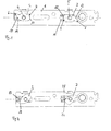
- FIG. 1 is a bottom view of a component 1 - shown in this case a base plate of a corner bearing fitting - which is to be fastened by means of sliding blocks 2, 3 to a profile with an undercut groove.
- the sliding blocks 2, 3 are aligned in the longitudinal direction of the component 1 and are thus in an assembly position.
- the sliding blocks 2, 3 are rotatable about a pivot point 4, 5.
- the sliding blocks 2, 3 each have two ends 6, 7 and 8, 9, which are arranged opposite each other and have differently curved end-side contact surfaces 10, 11 and 12, 13.
- the contact surfaces 10, 12 are further away from the pivot point 4, 5 and are more curved. Under a contact surface 10, 12, which is farther away from the pivot point 4, 5, this is understood to mean a surface which has at least one point or point which is farther away from the pivot point 4, 5 than all points of the opposite Contact surface 11, 13.
- the mounting aid 14 is supported on the one hand on the component 1 and on the other hand on the sliding block 2.
- the mounting aid 14 is designed to be elastic in order to be able to exert a certain force on the sliding block 2.
- a spring element 16 is materially connected. With its section 17, the spring element 16 presses against the sliding block 2 and thereby keeps it in its mounting position.
- the sliding block 2 has at both ends 6, 7 recesses 18, 19, where a projection 20 of the mounting aid 14 can come to rest when the sliding block 2 has been rotated into an operating position.
- the projection 20 is a positional fixation, since the nut 2 due to the interaction of the recesses 18 and 19 with the projection 20 can not be rotated back into its mounting position when the projection 20 due to the spring element 16, with which it is connected, rebounded is.
- FIG. 3 The sectional view of FIG. 3 can be seen that the sliding block 2 is held by the mounting aid 14 from the component 1 spaced. Evident is also a screw 21 which is partially screwed into the sliding block 2.
- the projection 20 extends through the mounting aid 14 on the one hand and protrudes to the other in a viewing window 22 of the component 1.
- the function of a position indicator is realized by the projection 20.
- the projection 20 protrudes into the viewing window 22, the projection 20 is held by the sliding block 2 in the position shown. If the sliding block 2 is rotated into an operating position, it releases the projection 20 so that it can move out of the viewing window 22 due to the spring element 16. This means that the sliding block 2 is in an operating position.
- the projection 20 then realizes a positional fixing for the sliding block 2.
- the spring element 16 can be regarded as a component of the position indicator or position fixing.
- the sliding blocks 2, 3 are shown in a twisted position.
- the sections 17, 23 were released, leaving the projection 20 at the recess 18 and a corresponding projection, which is arranged opposite the portion 23, rests against the recess 24 of the sliding block 3.
- the sliding blocks 2, 3 are not yet in a full operating position, but can not be moved back to a mounting position.
- FIG. 5 an alternative embodiment of a sliding block 30 is shown.
- the sliding block 30 also has differently curved contact surfaces 33, 34 at its opposite ends 31, 32.
- the contact surface 34 also has a recess 35 into which a nose 36 of the mounting aid 37 engages.
- the nose 36 is disposed on a rib 38.
- the recess 35 is followed by a flat surface 70, which prevents over-rotation of the sliding block 30 in the groove.
- the end 32 is held by a rib 39, so that the sliding block 30 is rotationally fixed in a mounting position.
- the ribs 38, 39 are deflected, so that the sliding block 30 can move into an operating position.
- the sliding block 30 is formed asymmetrically with respect to its pivot point 40.
- FIG. 6 is a sectional view through the in the FIG. 5 shown arrangement along the line VI - VI shown. Again, it can be seen that a projection 41 is held by the sliding block 30 in a viewing window 42.
- the mounting aid 37 holds the sliding block 30 spaced from the component 1.
- the sliding block 30 is stepped.
- the sliding block 30 is held by a screw 43 to the component 1.
- FIG. 7 shows the nut 30 in a twisted position. Due to the spring element 44, the projection 41 has moved out of the viewing window 42, so that a deviating from the mounting position situation is displayed. Because the spring element 44 has been released, it now blocks the sliding block 30 so that it can not be transferred back to its mounting position.
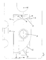
- FIG. 8 shows a frame profile 60 with an undercut groove 61.
- the width of the undercut groove 61 in the groove bottom 62, the groove opening 63 and the width of the undercut 64 vary.
- the sliding blocks shown in the previous figures are suitable to secure the component 1, even if the variations mentioned consist of profile to profile.
- FIG. 8 is the nut 2 in a mounting position. It can therefore be inserted through the slot opening 63. Due to the mounting aid 14, it is held there on the one hand in a rotationally fixed manner and, on the other hand, kept at a distance from the component 1.
- the screw 20 can be rotated relative to the sliding block 2 and it turns in the FIG. 10 shown situation, wherein the sliding block 2 is applied to the undercuts 64, 65 and the component 1 is clamped to the undercut groove 61. This means that the Undercuts 64, 65 are clamped between the nut 2 and the component 1.
Landscapes
- Engineering & Computer Science (AREA)
- Mechanical Engineering (AREA)
- General Engineering & Computer Science (AREA)
- Connection Of Plates (AREA)
- Wing Frames And Configurations (AREA)
- Support Devices For Sliding Doors (AREA)
Applications Claiming Priority (1)
| Application Number | Priority Date | Filing Date | Title |
|---|---|---|---|
| DE102008045080A DE102008045080A1 (de) | 2008-08-29 | 2008-08-29 | Nutenstein |
Publications (2)
| Publication Number | Publication Date |
|---|---|
| EP2159432A2 true EP2159432A2 (fr) | 2010-03-03 |
| EP2159432A3 EP2159432A3 (fr) | 2012-08-29 |
Family
ID=41426338
Family Applications (1)
| Application Number | Title | Priority Date | Filing Date |
|---|---|---|---|
| EP09168071A Withdrawn EP2159432A3 (fr) | 2008-08-29 | 2009-08-18 | Coulisseau |
Country Status (3)
| Country | Link |
|---|---|
| EP (1) | EP2159432A3 (fr) |
| CN (1) | CN101666345A (fr) |
| DE (1) | DE102008045080A1 (fr) |
Cited By (6)
| Publication number | Priority date | Publication date | Assignee | Title |
|---|---|---|---|---|
| DE202010013011U1 (de) | 2010-11-29 | 2011-02-24 | Simonswerk, Gesellschaft mit beschränkter Haftung | Befestigungsanordnung für die Montage von Beschlagteilen |
| EP2415954A1 (fr) * | 2010-08-03 | 2012-02-08 | Sotralu | Ferrure en applique comportant une bride de fixation |
| RU2569772C2 (ru) * | 2011-08-11 | 2015-11-27 | Рото Франк Аг | Система крепления для крепления конструктивного элемента к пазу окна, двери или подобному |
| CN110130727A (zh) * | 2019-06-19 | 2019-08-16 | 深圳好博窗控技术有限公司 | 一种五金安装结构 |
| CN110185319A (zh) * | 2019-06-19 | 2019-08-30 | 深圳好博窗控技术有限公司 | 一种安装结构 |
| DE102019130856A1 (de) * | 2019-11-15 | 2021-05-20 | Hettich-Heinze Gmbh & Co. Kg | Befestigungsvorrichtung und Montageeinheit |
Families Citing this family (1)
| Publication number | Priority date | Publication date | Assignee | Title |
|---|---|---|---|---|
| DE102008045071A1 (de) * | 2008-08-29 | 2010-03-18 | Roto Frank Ag | Nutensteinanordnung |
Citations (1)
| Publication number | Priority date | Publication date | Assignee | Title |
|---|---|---|---|---|
| DE20113607U1 (de) | 2001-08-09 | 2001-10-31 | Gretsch-Unitas GmbH Baubeschläge, 71254 Ditzingen | Drehkipp-Beschlag |
Family Cites Families (8)
| Publication number | Priority date | Publication date | Assignee | Title |
|---|---|---|---|---|
| DE4300997A1 (de) * | 1993-01-15 | 1994-07-21 | Wilke Heinrich Hewi Gmbh | Vorrichtung zur Befestigung eines plattenförmigen Bauteils an einer Wand o. dgl. |
| DE59510377D1 (de) * | 1994-10-20 | 2002-10-24 | Schueco Int Kg | Adapter |
| FR2754576B1 (fr) * | 1996-10-16 | 1998-11-27 | Rapid Sa | Ecrou a montage par clippage sur un profile |
| DE10154967B4 (de) * | 2001-11-08 | 2006-12-14 | Visolux Zweigniederlassung Der Pepperl + Fuchs Gmbh | Klemmvorrichtung zur Befestigung von Bauelementen an mit einer T-Nut versehenen Halteelementen |
| DE20207435U1 (de) * | 2002-05-11 | 2003-09-25 | Transnorm System GmbH, 31177 Harsum | Profilelement, insbesondere für Seitenwangen eines Fördersystems |
| US7497651B2 (en) * | 2003-04-16 | 2009-03-03 | Sportrack Llc | Securement mechanism |
| NL1029499C2 (nl) * | 2005-07-12 | 2007-01-15 | Walraven Holding Bv J Van | Bevestigingssamenstel. |
| DE102006013332A1 (de) * | 2006-03-21 | 2007-09-27 | SCHÜCO International KG | Fenster- oder Türelement mit einem automatischen Antrieb |
-
2008
- 2008-08-29 DE DE102008045080A patent/DE102008045080A1/de not_active Withdrawn
-
2009
- 2009-08-18 EP EP09168071A patent/EP2159432A3/fr not_active Withdrawn
- 2009-08-28 CN CN200910205702A patent/CN101666345A/zh active Pending
Patent Citations (1)
| Publication number | Priority date | Publication date | Assignee | Title |
|---|---|---|---|---|
| DE20113607U1 (de) | 2001-08-09 | 2001-10-31 | Gretsch-Unitas GmbH Baubeschläge, 71254 Ditzingen | Drehkipp-Beschlag |
Cited By (11)
| Publication number | Priority date | Publication date | Assignee | Title |
|---|---|---|---|---|
| EP2415954A1 (fr) * | 2010-08-03 | 2012-02-08 | Sotralu | Ferrure en applique comportant une bride de fixation |
| FR2963633A1 (fr) * | 2010-08-03 | 2012-02-10 | Sotralu | Ferrure en applique comportant une bride de fixation |
| DE202010013011U1 (de) | 2010-11-29 | 2011-02-24 | Simonswerk, Gesellschaft mit beschränkter Haftung | Befestigungsanordnung für die Montage von Beschlagteilen |
| RU2569772C2 (ru) * | 2011-08-11 | 2015-11-27 | Рото Франк Аг | Система крепления для крепления конструктивного элемента к пазу окна, двери или подобному |
| CN110130727A (zh) * | 2019-06-19 | 2019-08-16 | 深圳好博窗控技术有限公司 | 一种五金安装结构 |
| CN110185319A (zh) * | 2019-06-19 | 2019-08-30 | 深圳好博窗控技术有限公司 | 一种安装结构 |
| EP3988752A4 (fr) * | 2019-06-19 | 2023-06-28 | (Shenzhen Hopo Window Control Technology Co., Ltd) | Structure de montage de matériel |
| EP3988751A4 (fr) * | 2019-06-19 | 2023-07-12 | (Shenzhen Hopo Window Control Technology Co., Ltd) | Structure de montage |
| CN110185319B (zh) * | 2019-06-19 | 2024-04-12 | 深圳好博窗控技术股份有限公司 | 一种安装结构 |
| CN110130727B (zh) * | 2019-06-19 | 2024-04-12 | 深圳好博窗控技术股份有限公司 | 一种五金安装结构 |
| DE102019130856A1 (de) * | 2019-11-15 | 2021-05-20 | Hettich-Heinze Gmbh & Co. Kg | Befestigungsvorrichtung und Montageeinheit |
Also Published As
| Publication number | Publication date |
|---|---|
| EP2159432A3 (fr) | 2012-08-29 |
| DE102008045080A1 (de) | 2010-03-18 |
| CN101666345A (zh) | 2010-03-10 |
Similar Documents
| Publication | Publication Date | Title |
|---|---|---|
| EP2159356B1 (fr) | Agencement de coulisseau | |
| EP2159432A2 (fr) | Coulisseau | |
| EP2875199B1 (fr) | Guide pour tringle de crémone | |
| DE102011080795B3 (de) | Befestigungsanordnung zur Befestigung eines Bauteils an einer Nut eines Fensters, einer Tür oder dergleichen | |
| DE102010060764B3 (de) | Anschraubtasche für die Aufnahme von Bandzapfen eines Türbandes | |
| DE60031500T2 (de) | Rollblende | |
| EP1997989B1 (fr) | Elément de glissement pour un guide de porte coulisante | |
| EP3425155B1 (fr) | Dispositif de protection anti-pince doigt pour une porte | |
| DE102013100922B4 (de) | Laufteil zum Führen eines Möbelteils in einer Führungsrichtung über eine Führungsschiene und Möbelbeschlag | |
| WO2008052611A1 (fr) | Ensemble de ferrure pour portes, fenêtres ou analogues | |
| EP1898041B1 (fr) | Procedé et dispositif de montage d'accessoires sur cadres de bâtiments | |
| DE202008016071U1 (de) | Band zur scharniergelenkigen Verbindung eines Flügels an einem Rahmen | |
| DE102009010679A1 (de) | Vorhangsystem und Haltevorrichtung für ein Vorhangsystem | |
| DE102010028603B3 (de) | Beschlagteil zur Befestigung an einer C-förmigen Beschlagteilnut | |
| EP2540942B1 (fr) | Agencement de ferrure réglable | |
| DE10008685B4 (de) | Aushebesicherung für eine Heizkörperkonsole | |
| DE102006014553B4 (de) | Lehre zum Montieren von Verriegelungsbeschlaggarnituren sowie Montierverfahren einer Verriegelungsbeschlaggarnitur | |
| DE2628750B2 (de) | In einer Tafelöffnung anzuordnendes Meeinstrumentengehäuse mit federnden Befestigungsklemmen | |
| EP2562340A1 (fr) | Armature | |
| DE202010001441U1 (de) | Justiersystem für Bauelemente | |
| EP2240651A1 (fr) | Dispositif de baguettes profilées | |
| DE102009016791A1 (de) | Insektenschutztür oder -fenster | |
| DE10154477A1 (de) | Kupplungsvorrichtung | |
| EP3029243A1 (fr) | Systeme de butee d'une charniere de fenetre, d'une porte ou analogue | |
| DE202007011073U1 (de) | Befestigung für ein Scharnierband |
Legal Events
| Date | Code | Title | Description |
|---|---|---|---|
| PUAI | Public reference made under article 153(3) epc to a published international application that has entered the european phase |
Free format text: ORIGINAL CODE: 0009012 |
|
| AK | Designated contracting states |
Kind code of ref document: A2 Designated state(s): AT BE BG CH CY CZ DE DK EE ES FI FR GB GR HR HU IE IS IT LI LT LU LV MC MK MT NL NO PL PT RO SE SI SK SM TR |
|
| AX | Request for extension of the european patent |
Extension state: AL BA RS |
|
| PUAL | Search report despatched |
Free format text: ORIGINAL CODE: 0009013 |
|
| AK | Designated contracting states |
Kind code of ref document: A3 Designated state(s): AT BE BG CH CY CZ DE DK EE ES FI FR GB GR HR HU IE IS IT LI LT LU LV MC MK MT NL NO PL PT RO SE SI SK SM TR |
|
| AX | Request for extension of the european patent |
Extension state: AL BA RS |
|
| RIC1 | Information provided on ipc code assigned before grant |
Ipc: E05C 1/00 20060101ALI20120720BHEP Ipc: F16B 37/04 20060101AFI20120720BHEP |
|
| STAA | Information on the status of an ep patent application or granted ep patent |
Free format text: STATUS: THE APPLICATION IS DEEMED TO BE WITHDRAWN |
|
| 18D | Application deemed to be withdrawn |
Effective date: 20130301 |