EP2159455B1 - Steuervorrichtung eines computergesteuerten Kraftfahrzeuggetriebes - Google Patents
Steuervorrichtung eines computergesteuerten Kraftfahrzeuggetriebes Download PDFInfo
- Publication number
- EP2159455B1 EP2159455B1 EP09305749A EP09305749A EP2159455B1 EP 2159455 B1 EP2159455 B1 EP 2159455B1 EP 09305749 A EP09305749 A EP 09305749A EP 09305749 A EP09305749 A EP 09305749A EP 2159455 B1 EP2159455 B1 EP 2159455B1
- Authority
- EP
- European Patent Office
- Prior art keywords
- button
- gearbox
- mode
- modes
- computer
- Prior art date
- Legal status (The legal status is an assumption and is not a legal conclusion. Google has not performed a legal analysis and makes no representation as to the accuracy of the status listed.)
- Not-in-force
Links
Images



Classifications
-
- G—PHYSICS
- G01—MEASURING; TESTING
- G01D—MEASURING NOT SPECIALLY ADAPTED FOR A SPECIFIC VARIABLE; ARRANGEMENTS FOR MEASURING TWO OR MORE VARIABLES NOT COVERED IN A SINGLE OTHER SUBCLASS; TARIFF METERING APPARATUS; MEASURING OR TESTING NOT OTHERWISE PROVIDED FOR
- G01D5/00—Mechanical means for transferring the output of a sensing member; Means for converting the output of a sensing member to another variable where the form or nature of the sensing member does not constrain the means for converting; Transducers not specially adapted for a specific variable
- G01D5/12—Mechanical means for transferring the output of a sensing member; Means for converting the output of a sensing member to another variable where the form or nature of the sensing member does not constrain the means for converting; Transducers not specially adapted for a specific variable using electric or magnetic means
- G01D5/244—Mechanical means for transferring the output of a sensing member; Means for converting the output of a sensing member to another variable where the form or nature of the sensing member does not constrain the means for converting; Transducers not specially adapted for a specific variable using electric or magnetic means influencing characteristics of pulses or pulse trains; generating pulses or pulse trains
-
- B—PERFORMING OPERATIONS; TRANSPORTING
- B60—VEHICLES IN GENERAL
- B60K—ARRANGEMENT OR MOUNTING OF PROPULSION UNITS OR OF TRANSMISSIONS IN VEHICLES; ARRANGEMENT OR MOUNTING OF PLURAL DIVERSE PRIME-MOVERS IN VEHICLES; AUXILIARY DRIVES FOR VEHICLES; INSTRUMENTATION OR DASHBOARDS FOR VEHICLES; ARRANGEMENTS IN CONNECTION WITH COOLING, AIR INTAKE, GAS EXHAUST OR FUEL SUPPLY OF PROPULSION UNITS IN VEHICLES
- B60K35/00—Instruments specially adapted for vehicles; Arrangement of instruments in or on vehicles
- B60K35/10—Input arrangements, i.e. from user to vehicle, associated with vehicle functions or specially adapted therefor
-
- B—PERFORMING OPERATIONS; TRANSPORTING
- B60—VEHICLES IN GENERAL
- B60K—ARRANGEMENT OR MOUNTING OF PROPULSION UNITS OR OF TRANSMISSIONS IN VEHICLES; ARRANGEMENT OR MOUNTING OF PLURAL DIVERSE PRIME-MOVERS IN VEHICLES; AUXILIARY DRIVES FOR VEHICLES; INSTRUMENTATION OR DASHBOARDS FOR VEHICLES; ARRANGEMENTS IN CONNECTION WITH COOLING, AIR INTAKE, GAS EXHAUST OR FUEL SUPPLY OF PROPULSION UNITS IN VEHICLES
- B60K35/00—Instruments specially adapted for vehicles; Arrangement of instruments in or on vehicles
- B60K35/20—Output arrangements, i.e. from vehicle to user, associated with vehicle functions or specially adapted therefor
- B60K35/25—Output arrangements, i.e. from vehicle to user, associated with vehicle functions or specially adapted therefor using haptic output
-
- F—MECHANICAL ENGINEERING; LIGHTING; HEATING; WEAPONS; BLASTING
- F16—ENGINEERING ELEMENTS AND UNITS; GENERAL MEASURES FOR PRODUCING AND MAINTAINING EFFECTIVE FUNCTIONING OF MACHINES OR INSTALLATIONS; THERMAL INSULATION IN GENERAL
- F16H—GEARING
- F16H59/00—Control inputs to control units of change-speed- or reversing-gearings for conveying rotary motion
- F16H59/02—Selector apparatus
- F16H59/08—Range selector apparatus
-
- G—PHYSICS
- G01—MEASURING; TESTING
- G01D—MEASURING NOT SPECIALLY ADAPTED FOR A SPECIFIC VARIABLE; ARRANGEMENTS FOR MEASURING TWO OR MORE VARIABLES NOT COVERED IN A SINGLE OTHER SUBCLASS; TARIFF METERING APPARATUS; MEASURING OR TESTING NOT OTHERWISE PROVIDED FOR
- G01D11/00—Component parts of measuring arrangements not specially adapted for a specific variable
- G01D11/28—Structurally-combined illuminating devices
-
- G—PHYSICS
- G01—MEASURING; TESTING
- G01D—MEASURING NOT SPECIALLY ADAPTED FOR A SPECIFIC VARIABLE; ARRANGEMENTS FOR MEASURING TWO OR MORE VARIABLES NOT COVERED IN A SINGLE OTHER SUBCLASS; TARIFF METERING APPARATUS; MEASURING OR TESTING NOT OTHERWISE PROVIDED FOR
- G01D5/00—Mechanical means for transferring the output of a sensing member; Means for converting the output of a sensing member to another variable where the form or nature of the sensing member does not constrain the means for converting; Transducers not specially adapted for a specific variable
- G01D5/02—Mechanical means for transferring the output of a sensing member; Means for converting the output of a sensing member to another variable where the form or nature of the sensing member does not constrain the means for converting; Transducers not specially adapted for a specific variable using mechanical means
-
- G—PHYSICS
- G01—MEASURING; TESTING
- G01D—MEASURING NOT SPECIALLY ADAPTED FOR A SPECIFIC VARIABLE; ARRANGEMENTS FOR MEASURING TWO OR MORE VARIABLES NOT COVERED IN A SINGLE OTHER SUBCLASS; TARIFF METERING APPARATUS; MEASURING OR TESTING NOT OTHERWISE PROVIDED FOR
- G01D7/00—Indicating measured values
-
- G—PHYSICS
- G05—CONTROLLING; REGULATING
- G05G—CONTROL DEVICES OR SYSTEMS INSOFAR AS CHARACTERISED BY MECHANICAL FEATURES ONLY
- G05G1/00—Controlling members, e.g. knobs or handles; Assemblies or arrangements thereof; Indicating position of controlling members
- G05G1/08—Controlling members for hand actuation by rotary movement, e.g. hand wheels
-
- G—PHYSICS
- G05—CONTROLLING; REGULATING
- G05G—CONTROL DEVICES OR SYSTEMS INSOFAR AS CHARACTERISED BY MECHANICAL FEATURES ONLY
- G05G5/00—Means for preventing, limiting or returning the movements of parts of a control mechanism, e.g. locking controlling member
- G05G5/03—Means for enhancing the operator's awareness of arrival of the controlling member at a command or datum position; Providing feel, e.g. means for creating a counterforce
-
- G—PHYSICS
- G05—CONTROLLING; REGULATING
- G05G—CONTROL DEVICES OR SYSTEMS INSOFAR AS CHARACTERISED BY MECHANICAL FEATURES ONLY
- G05G5/00—Means for preventing, limiting or returning the movements of parts of a control mechanism, e.g. locking controlling member
- G05G5/06—Means for preventing, limiting or returning the movements of parts of a control mechanism, e.g. locking controlling member for holding members in one or a limited number of definite positions only
-
- B—PERFORMING OPERATIONS; TRANSPORTING
- B60—VEHICLES IN GENERAL
- B60K—ARRANGEMENT OR MOUNTING OF PROPULSION UNITS OR OF TRANSMISSIONS IN VEHICLES; ARRANGEMENT OR MOUNTING OF PLURAL DIVERSE PRIME-MOVERS IN VEHICLES; AUXILIARY DRIVES FOR VEHICLES; INSTRUMENTATION OR DASHBOARDS FOR VEHICLES; ARRANGEMENTS IN CONNECTION WITH COOLING, AIR INTAKE, GAS EXHAUST OR FUEL SUPPLY OF PROPULSION UNITS IN VEHICLES
- B60K2360/00—Indexing scheme associated with groups B60K35/00 or B60K37/00 relating to details of instruments or dashboards
- B60K2360/126—Rotatable input devices for instruments
-
- F—MECHANICAL ENGINEERING; LIGHTING; HEATING; WEAPONS; BLASTING
- F16—ENGINEERING ELEMENTS AND UNITS; GENERAL MEASURES FOR PRODUCING AND MAINTAINING EFFECTIVE FUNCTIONING OF MACHINES OR INSTALLATIONS; THERMAL INSULATION IN GENERAL
- F16H—GEARING
- F16H59/00—Control inputs to control units of change-speed- or reversing-gearings for conveying rotary motion
- F16H59/02—Selector apparatus
- F16H2059/0239—Up- and down-shift or range or mode selection by repeated movement
-
- F—MECHANICAL ENGINEERING; LIGHTING; HEATING; WEAPONS; BLASTING
- F16—ENGINEERING ELEMENTS AND UNITS; GENERAL MEASURES FOR PRODUCING AND MAINTAINING EFFECTIVE FUNCTIONING OF MACHINES OR INSTALLATIONS; THERMAL INSULATION IN GENERAL
- F16H—GEARING
- F16H59/00—Control inputs to control units of change-speed- or reversing-gearings for conveying rotary motion
- F16H59/02—Selector apparatus
- F16H59/08—Range selector apparatus
- F16H2059/081—Range selector apparatus using knops or discs for rotary range selection
-
- F—MECHANICAL ENGINEERING; LIGHTING; HEATING; WEAPONS; BLASTING
- F16—ENGINEERING ELEMENTS AND UNITS; GENERAL MEASURES FOR PRODUCING AND MAINTAINING EFFECTIVE FUNCTIONING OF MACHINES OR INSTALLATIONS; THERMAL INSULATION IN GENERAL
- F16H—GEARING
- F16H63/00—Control outputs from the control unit to change-speed- or reversing-gearings for conveying rotary motion or to other devices than the final output mechanism
- F16H63/40—Control outputs from the control unit to change-speed- or reversing-gearings for conveying rotary motion or to other devices than the final output mechanism comprising signals other than signals for actuating the final output mechanisms
- F16H63/42—Ratio indicator devices
- F16H2063/423—Range indicators for automatic transmissions, e.g. showing selected range or mode
-
- F—MECHANICAL ENGINEERING; LIGHTING; HEATING; WEAPONS; BLASTING
- F16—ENGINEERING ELEMENTS AND UNITS; GENERAL MEASURES FOR PRODUCING AND MAINTAINING EFFECTIVE FUNCTIONING OF MACHINES OR INSTALLATIONS; THERMAL INSULATION IN GENERAL
- F16H—GEARING
- F16H61/00—Control functions within control units of change-speed- or reversing-gearings for conveying rotary motion ; Control of exclusively fluid gearing, friction gearing, gearings with endless flexible members or other particular types of gearing
- F16H61/24—Providing feel, e.g. to enable selection
Definitions
- the invention relates to the technical sector of gearbox control means, especially for motor vehicles, and more particularly relates to a controlled automatic transmission.
- This type of box is subject to various means of the calculator type, actuator, electronic control unit, .... to switch, at will, from a manual mode to an automatic mode.
- a manual mode the positions M + and M- (sequential control) are used to raise and lower the speeds by acting on an operating member.
- P - R - N - D positions for the engagement and the selection, from the aforementioned control member, of said P (parking brake), R (reverse), N (dead point), D (normal driving with all reports).
- P parking brake
- R reverse
- N dead point
- D normal driving with all reports
- this type of control by means of a rotary knob, requires specific means, on the one hand, for the angular indexing of the button in different positions corresponding to the selected mode and to the selected state and, on the other hand, part, means to know the positioning of the organ.
- the problem that proposes to To solve the invention is to be able, from this button, to select the modes P - R - N - D and M, not on the stable states of this button, as is apparent from the state of the art, but on the displacements between stable states of this button.
- the magnetic type means are constituted by a series of magnets whose North and South poles are alternately arranged on the corresponding part of the button and the support.
- the portion of the button is constituted by an inner ring, while the portion of the support is constituted by an outer ring, said rings being arranged in a concentric manner.
- the magnets are distributed on the periphery of the crowns.
- Another problem to be solved by the invention is to detect the passage of the South poles and North poles, to determine the number of steps performed and the direction of rotation of the control button.
- the button is subject to 2 sensors to detect the change of stable position and indicate the direction of rotation.
- the sensors consist of two Hall effect sensors mounted near the magnets of the rotating part of the knob.
- the Hall effect signals of the button are transmitted to a microcontroller which sends a signal to each of the LEDs corresponding to the different modes and at different positions in the selected modes, said microcontroller being also subject to the element acting as a contactor.
- the microcontroller notifies the control computer modes P - R - N - D of the desired position by the driver.
- the button (1) and the support (2) are subject to magnetic-type means, capable of exerting an attractive force, creating the billing effect (swallowing and then abutment ) sought by acting as notches, and corresponding to a stable angular indexing position.
- the stop effect is canceled when a force is exerted on the button (1).
- a button portion (1) and a portion of the support (2) are equipped with permanent magnets (3) and (4) whose North poles and the South poles are alternately arranged to achieve the stable position when the South pole of a magnet is positioned in front of the North Pole of another magnet.
- the button (1) delimits a ring (1a) whose inner face is equipped with magnets (4) distributed around its circumference and angularly offset.
- the fixed support (2) has a ring (2a) whose outer face is equipped with magnets (3).
- the rotary assembly of the button (1) relative to the support (2) is effected by a coaxial centering surface (1b) engaged inside the ring (2a) of the support (2).
- the rings (1a) and (2a), respectively with the alternation of the magnets (4) and (3), are arranged in a concentric manner, the magnets being distributed over the periphery of the rings.
- the number of magnets (3) and (4) is a function of the number of notches desired.
- the fixing of the different magnets on the crowns is carried out by any known and appropriate means.
- the South pole of one of the magnets (4) of the crown (1a) passes in front of the South pole of one of the magnets (3) of the crown ( 2a) of the support (2) in a movement that requires effort.
- the two magnets are positioned one in front of the other corresponding to a stable position from which, it is necessary to overcome a force to move to another position angularly offset.
- the button is not angularly oriented, but can be driven continuously, in a 360 ° direction. one way or the other, with the aim of selecting the modes P - R - N - D and M not on the stable states of this button, but on the displacements between the stable states of this button.
- the indications correspond, either to the will of the driver, or to the position of the box
- the button is slaved to an element (5) acting as a contactor to allow the passage from one mode to another.
- the button can turn but does not generate a change of mode, therefore no change of light indication.
- the rotary knob (1) makes it possible to select the modes P-R-N-D and M on an automatic gearbox, while being able to display and select them via the different LEDs corresponding to the positions P - R - N - D and M.
- the rotation of the button (1) in the clockwise direction, controls the higher speed, while a rotation inverse of said button (1) controls the lower speed.
- the button then allows you to select the P - R - N - D or M modes again.
- the switch (5) can be constituted by a pusher arranged coaxially with the rotary knob (1) constituting the fixed support of the latter.
- the rotary knob (1) is subject to sensors for detecting each stable position and indicating the direction of rotation.
- the sensors consist of two Hall effect sensors mounted near the magnets (4) of the rotating part (1), namely the inner ring of the latter.
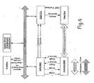
- the Hall effect signals of the rotary knob (1) are transmitted to a microcontroller (7) which sends a signal to each of the LEDs indicating the different positions P - R - N - D and M.
- the microcontroller is also subject to the trigger of selection of the mode presented by the button.
- a chronogram Fig. 7 signals Hall effect sensors, that the falling edges can detect a beginning of movement from the stable position 1 to the stable position 2, while the rising edges can confirm the end of the movement of the stable position 1 to the position stable 2.
- Event Rotary Knob ⁇ No mvt
Landscapes
- Engineering & Computer Science (AREA)
- Physics & Mathematics (AREA)
- General Physics & Mathematics (AREA)
- Automation & Control Theory (AREA)
- Mechanical Engineering (AREA)
- General Engineering & Computer Science (AREA)
- Chemical & Material Sciences (AREA)
- Combustion & Propulsion (AREA)
- Transportation (AREA)
- Arrangement Or Mounting Of Control Devices For Change-Speed Gearing (AREA)
- Control Of Transmission Device (AREA)
- Mechanical Control Devices (AREA)
Claims (5)
- Schaltvorrichtung eines von einem Rechner abhängigen Automobilgetriebes, im Automatikbetrieb der Schaltung mit den Positionen für die Betriebsarten P, R, N und D und im manuellen Betrieb der Schaltung mit der Position für die Betriebsart M, mit einem Organ für die Schaltung und Auswahl der verschiedenen Betriebsarten in Form eines frei drehbaren Schaltknopfes (1), der kontinuierlich über 360° in die eine oder andere Richtung mitgeführt werden kann, dadurch gekennzeichnet, dass der Schaltknopf abhängig ist von:- magnetartigen Einrichtungen (3 und 4), die in vorgegebenen Positionen auf einem Teil des Knopfes und auf einem Teil einer Halterung (2) winkelig versetzt und geeignet sind, eine Anziehungskraft auszuüben und dabei - entsprechend einer stabilen winkeligen Indexposition - einen Raststufeneffekt vergleichbar mit einer Kugelrastung zu erzeugen, wobei der besagte Kugelrasteffekt bei einer Kraftausübung auf den Knopf annulliert wird und jede der stabilen Positionen den einzelnen Positionen der verschiedenen Betriebsarten P, R, N, D und M entspricht, jeweils mit einer Leuchtanzeige in Form einer LED;- Einrichtungen in Form von Hall-Effekt-Sensoren zur Erkennung der Verschiebung von einer stabilen Position zu einer anderen stabilen Position und zur Anzeige der Drehrichtung;- einem als Schalter dienenden Element (5) zum Wechsel von einer Betriebsart zur anderen;- einem Rechner für die Erfassung der vom Getriebe stammenden Daten;- einem Rechner für das Getriebemanagement zur Wahl und Steuerung der Betriebsarten P, R, N, D und M in Verbindung mit einem Aktuator;- einem Mikrocontroller, dem die Signale der Hall-Effekt-Sensoren gemeldet werden und der jeder den verschiedenen Positionen der einzelnen Betriebsarten entsprechenden LED ein Signal zuschickt, wobei der besagte Mikrocontroller auch von dem als Schalter dienenden Element (5) abhängig ist, um je nach der vom Fahrer gewählten Position dem Rechner für das Getriebemanagement die Steuerung der Betriebsarten P, R, N, D und M zu übermitteln.
- Vorrichtung nach Anspruch 1, dadurch gekennzeichnet, dass die magnetartigen Einrichtungen aus einer Reihe von Magneten (3, 4) bestehen, deren Nord- und Südpole auf dem entsprechenden Teil des Knopfes und der Halterung alternierend angeordnet sind.
- Vorrichtung nach einem der Ansprüche 1 und 2, dadurch gekennzeichnet, dass der Knopfteil aus einem inneren Kranz (1a) besteht, während der Halterungsteil aus einem äußeren Kranz (2a) besteht, wobei die besagten Kränze konzentrisch angeordnet sind.
- Vorrichtung nach einem der Ansprüche 2 und 3, dadurch gekennzeichnet, dass die Magneten über den Rand der Kränze verteilt sind.
- Vorrichtung nach Anspruch 2, dadurch kennzeichnet, dass die Hall-Effekt-Sensoren (6) in der Nähe der Magneten des Drehteils des Knopfes (1) angebracht sind.
Applications Claiming Priority (1)
| Application Number | Priority Date | Filing Date | Title |
|---|---|---|---|
| FR0855783A FR2935454B1 (fr) | 2008-08-28 | 2008-08-28 | Dispositif de commande d'une boite de vitesse de vehicule automobile assujettie a un calculateur |
Publications (2)
| Publication Number | Publication Date |
|---|---|
| EP2159455A1 EP2159455A1 (de) | 2010-03-03 |
| EP2159455B1 true EP2159455B1 (de) | 2012-02-29 |
Family
ID=40497584
Family Applications (1)
| Application Number | Title | Priority Date | Filing Date |
|---|---|---|---|
| EP09305749A Not-in-force EP2159455B1 (de) | 2008-08-28 | 2009-08-12 | Steuervorrichtung eines computergesteuerten Kraftfahrzeuggetriebes |
Country Status (4)
| Country | Link |
|---|---|
| EP (1) | EP2159455B1 (de) |
| AT (1) | ATE547656T1 (de) |
| ES (1) | ES2380294T3 (de) |
| FR (1) | FR2935454B1 (de) |
Cited By (1)
| Publication number | Priority date | Publication date | Assignee | Title |
|---|---|---|---|---|
| DE102018125077A1 (de) * | 2018-10-10 | 2020-04-16 | Bcs Automotive Interface Solutions Gmbh | Magnetischer Drehsteller und Kraftfahrzeugbedieneinheit |
Families Citing this family (8)
| Publication number | Priority date | Publication date | Assignee | Title |
|---|---|---|---|---|
| DE102011085146A1 (de) | 2011-10-25 | 2013-04-25 | Preh Gmbh | Bedienelement mit magnetischer Rückstellung |
| DE102012222237A1 (de) * | 2012-08-10 | 2014-05-15 | Preh Gmbh | Bedienelement mit Magnethaptik |
| CN103470746B (zh) * | 2013-09-04 | 2015-11-18 | 重庆长安汽车股份有限公司 | 一种旋钮电子换挡器及其与周边构件的搭接结构 |
| DE102013014792A1 (de) * | 2013-09-09 | 2015-03-12 | Leopold Kostal Gmbh & Co. Kg | Bildschirmbasiertes Fahrzeugbediensystem |
| US9810314B2 (en) | 2015-02-25 | 2017-11-07 | Kongsberg Driveline Systems I, Inc. | Rotary shifter assembly |
| EP3303882B1 (de) | 2015-06-03 | 2019-01-30 | Kongsberg Automotive AB | Schalthebel zur steuerung des getriebes eines kraftfahrzeugs und verfahren zur steuerung des getriebes eines kraftfahrzeugs mithilfe eines schalthebels |
| KR102402603B1 (ko) * | 2017-12-29 | 2022-05-26 | 에스엘 주식회사 | 액츄에이터 및 이를 포함하는 차량용 변속 장치 |
| KR102697977B1 (ko) | 2019-09-09 | 2024-08-22 | 에스엘 주식회사 | 차량용 변속 장치 |
Family Cites Families (8)
| Publication number | Priority date | Publication date | Assignee | Title |
|---|---|---|---|---|
| FR2804240B1 (fr) * | 2000-01-26 | 2002-05-17 | Dav | Dispositif de commande de fonctions electriques dans l'automobile par commutation magnetique |
| US6564661B2 (en) * | 2001-02-01 | 2003-05-20 | Grand Haven Stamped Products, Division Of Jsj Corporation | Storable shifter with electronic gear shift reset |
| FR2836974B1 (fr) * | 2002-03-06 | 2005-02-11 | Renault | Dispositif electronique et procede de selection de vitesses pour boite de vitesses automatiques |
| US7571662B2 (en) * | 2004-08-18 | 2009-08-11 | Jaguars Cars Limited | Selector mechanism for a motor vehicle transmission |
| DE102005018380A1 (de) | 2005-04-21 | 2006-11-09 | Leopold Kostal Gmbh & Co. Kg | Drehsteller |
| ES2284352B1 (es) * | 2005-09-30 | 2008-09-16 | Fico Triad, S.A. | Dispositivo de mando integrado de arranque, paro, seleccion de modo y cambio de marchas para vehiculo. |
| DE102005061285A1 (de) * | 2005-12-20 | 2007-06-21 | Lemförder Electronic GmbH | Wähleinrichtung zum Schalten eines Fahrzeuggetriebes |
| GB2441337B (en) * | 2006-09-01 | 2011-02-02 | Ford Global Tech Llc | An electric selector control system for a motor vehicle transmission |
-
2008
- 2008-08-28 FR FR0855783A patent/FR2935454B1/fr not_active Expired - Fee Related
-
2009
- 2009-08-12 AT AT09305749T patent/ATE547656T1/de active
- 2009-08-12 EP EP09305749A patent/EP2159455B1/de not_active Not-in-force
- 2009-08-12 ES ES09305749T patent/ES2380294T3/es active Active
Cited By (1)
| Publication number | Priority date | Publication date | Assignee | Title |
|---|---|---|---|---|
| DE102018125077A1 (de) * | 2018-10-10 | 2020-04-16 | Bcs Automotive Interface Solutions Gmbh | Magnetischer Drehsteller und Kraftfahrzeugbedieneinheit |
Also Published As
| Publication number | Publication date |
|---|---|
| ES2380294T3 (es) | 2012-05-10 |
| EP2159455A1 (de) | 2010-03-03 |
| FR2935454A1 (fr) | 2010-03-05 |
| ATE547656T1 (de) | 2012-03-15 |
| FR2935454B1 (fr) | 2011-10-07 |
Similar Documents
| Publication | Publication Date | Title |
|---|---|---|
| EP2159455A1 (de) | Steuervorrichtung eines computergesteuerten Kraftfahrzeuggetriebes | |
| EP2534396B1 (de) | Vorrichtung zur erkennung der neutralen position eines hebels zum wählen und schalten von gängen in einem motorfahrzeuggetriebe | |
| EP3350012B1 (de) | Automatikgetriebeschalthebel für ein kraftfahrzeug und verfahren zur auswahl eines autonomen fahrmodus | |
| FR2764028A1 (fr) | Dispositif de positionnement | |
| EP1882871A1 (de) | Kraftfahrzeuggetriebe mit einem magnetischen Hall-Sensor | |
| WO2002075179A1 (fr) | Dispositif de transmission automatisee a transfert de couple, en particulier pour vehicule automobile | |
| FR2794835A1 (fr) | Procede de mise en oeuvre d'un dispositif de boite de vitesses et dispositif correspondant | |
| FR2715353A1 (fr) | Dispositif de sélection pour appareil de commande automatique d'une boîte de vitesses d'automobile. | |
| FR2816554A1 (fr) | Systeme de transmission de vehicule et dispositif de changement de vitesse pour cette transmission | |
| EP2479073B1 (de) | Diebstahlsicherung für Lenksäule eines Kraftfahrzeugs | |
| WO2016005685A1 (fr) | Combine d'instruments numerique pour planche de bord de vehicule automobile a surface d'affichage modulable | |
| EP0990098B1 (de) | Vorrichtung zum elektromechanischen schalten eines gangwechselgetriebes | |
| EP0383688A1 (de) | Vorrichtung zum Detektieren des geschalteten Ganges eines Handschaltgetriebes, gekoppelt mit einem Schaltmechanismus für eine automatische Kupplung | |
| EP1108169B1 (de) | Elektrisch gesteuerte getriebeschalteinrichtung für ein kraftfahrzeug | |
| EP1990560A2 (de) | Steuervorrichtung eines ferngesteuerten Getriebes für Kraftfahrzeug | |
| FR3042448A1 (fr) | Dispositif de commande pour vehicule automobile dote d’un systeme de conduite autonome. | |
| FR3072518A1 (fr) | Dispositif mecatronique pour l'actionnement d'un dispositif de freinage, frein a disque et procede de freinage associes | |
| FR2806143A1 (fr) | Dispositif de transmission automatisee a transfert de couple, en particulier pour vehicule automobile | |
| EP1186809B1 (de) | Getriebe mit Schaltaktuator | |
| FR2539360A1 (fr) | Dispositif pour la deconnexion d'un organe indicateur de direction d'un vehicule automobile | |
| EP1980772A1 (de) | Steuergitter für Kraftfahrzeuggetriebe und mit einem solchen Gitter ausgestattetes Getriebe | |
| FR2532894A1 (de) | ||
| FR2924680A1 (fr) | Bateau a moteur dont l'organe de commande de vitesse est dispose au voisinage immediat du volant | |
| FR2797486A1 (fr) | Boite de vitesses | |
| EP0657322A1 (de) | Steurungsverfahren für ein Fahrzeug mit Elektromotor und Vorrichtung zur Durchführung des Verfahrens |
Legal Events
| Date | Code | Title | Description |
|---|---|---|---|
| PUAI | Public reference made under article 153(3) epc to a published international application that has entered the european phase |
Free format text: ORIGINAL CODE: 0009012 |
|
| AK | Designated contracting states |
Kind code of ref document: A1 Designated state(s): AT BE BG CH CY CZ DE DK EE ES FI FR GB GR HR HU IE IS IT LI LT LU LV MC MK MT NL NO PL PT RO SE SI SK SM TR |
|
| AX | Request for extension of the european patent |
Extension state: AL BA RS |
|
| 17P | Request for examination filed |
Effective date: 20100826 |
|
| 17Q | First examination report despatched |
Effective date: 20110111 |
|
| RIC1 | Information provided on ipc code assigned before grant |
Ipc: G01D 5/14 20060101ALI20110616BHEP Ipc: G05G 1/08 20060101ALI20110616BHEP Ipc: F16H 59/08 20060101AFI20110616BHEP Ipc: G05G 5/03 20080401ALI20110616BHEP Ipc: F16H 61/24 20060101ALI20110616BHEP Ipc: G05G 5/06 20060101ALI20110616BHEP |
|
| GRAP | Despatch of communication of intention to grant a patent |
Free format text: ORIGINAL CODE: EPIDOSNIGR1 |
|
| GRAS | Grant fee paid |
Free format text: ORIGINAL CODE: EPIDOSNIGR3 |
|
| GRAA | (expected) grant |
Free format text: ORIGINAL CODE: 0009210 |
|
| AK | Designated contracting states |
Kind code of ref document: B1 Designated state(s): AT BE BG CH CY CZ DE DK EE ES FI FR GB GR HR HU IE IS IT LI LT LU LV MC MK MT NL NO PL PT RO SE SI SK SM TR |
|
| REG | Reference to a national code |
Ref country code: GB Ref legal event code: FG4D Free format text: NOT ENGLISH Ref country code: CH Ref legal event code: EP |
|
| REG | Reference to a national code |
Ref country code: AT Ref legal event code: REF Ref document number: 547656 Country of ref document: AT Kind code of ref document: T Effective date: 20120315 |
|
| REG | Reference to a national code |
Ref country code: IE Ref legal event code: FG4D Free format text: LANGUAGE OF EP DOCUMENT: FRENCH |
|
| REG | Reference to a national code |
Ref country code: DE Ref legal event code: R096 Ref document number: 602009005622 Country of ref document: DE Effective date: 20120426 |
|
| REG | Reference to a national code |
Ref country code: ES Ref legal event code: FG2A Ref document number: 2380294 Country of ref document: ES Kind code of ref document: T3 Effective date: 20120510 |
|
| REG | Reference to a national code |
Ref country code: NL Ref legal event code: VDEP Effective date: 20120229 |
|
| LTIE | Lt: invalidation of european patent or patent extension |
Effective date: 20120229 |
|
| PG25 | Lapsed in a contracting state [announced via postgrant information from national office to epo] |
Ref country code: LT Free format text: LAPSE BECAUSE OF FAILURE TO SUBMIT A TRANSLATION OF THE DESCRIPTION OR TO PAY THE FEE WITHIN THE PRESCRIBED TIME-LIMIT Effective date: 20120229 Ref country code: IS Free format text: LAPSE BECAUSE OF FAILURE TO SUBMIT A TRANSLATION OF THE DESCRIPTION OR TO PAY THE FEE WITHIN THE PRESCRIBED TIME-LIMIT Effective date: 20120629 Ref country code: HR Free format text: LAPSE BECAUSE OF FAILURE TO SUBMIT A TRANSLATION OF THE DESCRIPTION OR TO PAY THE FEE WITHIN THE PRESCRIBED TIME-LIMIT Effective date: 20120229 Ref country code: NL Free format text: LAPSE BECAUSE OF FAILURE TO SUBMIT A TRANSLATION OF THE DESCRIPTION OR TO PAY THE FEE WITHIN THE PRESCRIBED TIME-LIMIT Effective date: 20120229 Ref country code: NO Free format text: LAPSE BECAUSE OF FAILURE TO SUBMIT A TRANSLATION OF THE DESCRIPTION OR TO PAY THE FEE WITHIN THE PRESCRIBED TIME-LIMIT Effective date: 20120529 |
|
| PG25 | Lapsed in a contracting state [announced via postgrant information from national office to epo] |
Ref country code: GR Free format text: LAPSE BECAUSE OF FAILURE TO SUBMIT A TRANSLATION OF THE DESCRIPTION OR TO PAY THE FEE WITHIN THE PRESCRIBED TIME-LIMIT Effective date: 20120530 Ref country code: FI Free format text: LAPSE BECAUSE OF FAILURE TO SUBMIT A TRANSLATION OF THE DESCRIPTION OR TO PAY THE FEE WITHIN THE PRESCRIBED TIME-LIMIT Effective date: 20120229 Ref country code: LV Free format text: LAPSE BECAUSE OF FAILURE TO SUBMIT A TRANSLATION OF THE DESCRIPTION OR TO PAY THE FEE WITHIN THE PRESCRIBED TIME-LIMIT Effective date: 20120229 Ref country code: PT Free format text: LAPSE BECAUSE OF FAILURE TO SUBMIT A TRANSLATION OF THE DESCRIPTION OR TO PAY THE FEE WITHIN THE PRESCRIBED TIME-LIMIT Effective date: 20120629 |
|
| REG | Reference to a national code |
Ref country code: AT Ref legal event code: MK05 Ref document number: 547656 Country of ref document: AT Kind code of ref document: T Effective date: 20120229 |
|
| REG | Reference to a national code |
Ref country code: IE Ref legal event code: FD4D |
|
| PG25 | Lapsed in a contracting state [announced via postgrant information from national office to epo] |
Ref country code: CY Free format text: LAPSE BECAUSE OF FAILURE TO SUBMIT A TRANSLATION OF THE DESCRIPTION OR TO PAY THE FEE WITHIN THE PRESCRIBED TIME-LIMIT Effective date: 20120229 |
|
| PG25 | Lapsed in a contracting state [announced via postgrant information from national office to epo] |
Ref country code: DK Free format text: LAPSE BECAUSE OF FAILURE TO SUBMIT A TRANSLATION OF THE DESCRIPTION OR TO PAY THE FEE WITHIN THE PRESCRIBED TIME-LIMIT Effective date: 20120229 Ref country code: PL Free format text: LAPSE BECAUSE OF FAILURE TO SUBMIT A TRANSLATION OF THE DESCRIPTION OR TO PAY THE FEE WITHIN THE PRESCRIBED TIME-LIMIT Effective date: 20120229 Ref country code: IE Free format text: LAPSE BECAUSE OF FAILURE TO SUBMIT A TRANSLATION OF THE DESCRIPTION OR TO PAY THE FEE WITHIN THE PRESCRIBED TIME-LIMIT Effective date: 20120229 Ref country code: SE Free format text: LAPSE BECAUSE OF FAILURE TO SUBMIT A TRANSLATION OF THE DESCRIPTION OR TO PAY THE FEE WITHIN THE PRESCRIBED TIME-LIMIT Effective date: 20120229 Ref country code: RO Free format text: LAPSE BECAUSE OF FAILURE TO SUBMIT A TRANSLATION OF THE DESCRIPTION OR TO PAY THE FEE WITHIN THE PRESCRIBED TIME-LIMIT Effective date: 20120229 Ref country code: SI Free format text: LAPSE BECAUSE OF FAILURE TO SUBMIT A TRANSLATION OF THE DESCRIPTION OR TO PAY THE FEE WITHIN THE PRESCRIBED TIME-LIMIT Effective date: 20120229 Ref country code: EE Free format text: LAPSE BECAUSE OF FAILURE TO SUBMIT A TRANSLATION OF THE DESCRIPTION OR TO PAY THE FEE WITHIN THE PRESCRIBED TIME-LIMIT Effective date: 20120229 Ref country code: CZ Free format text: LAPSE BECAUSE OF FAILURE TO SUBMIT A TRANSLATION OF THE DESCRIPTION OR TO PAY THE FEE WITHIN THE PRESCRIBED TIME-LIMIT Effective date: 20120229 |
|
| PG25 | Lapsed in a contracting state [announced via postgrant information from national office to epo] |
Ref country code: SK Free format text: LAPSE BECAUSE OF FAILURE TO SUBMIT A TRANSLATION OF THE DESCRIPTION OR TO PAY THE FEE WITHIN THE PRESCRIBED TIME-LIMIT Effective date: 20120229 |
|
| PLBE | No opposition filed within time limit |
Free format text: ORIGINAL CODE: 0009261 |
|
| STAA | Information on the status of an ep patent application or granted ep patent |
Free format text: STATUS: NO OPPOSITION FILED WITHIN TIME LIMIT |
|
| PG25 | Lapsed in a contracting state [announced via postgrant information from national office to epo] |
Ref country code: AT Free format text: LAPSE BECAUSE OF FAILURE TO SUBMIT A TRANSLATION OF THE DESCRIPTION OR TO PAY THE FEE WITHIN THE PRESCRIBED TIME-LIMIT Effective date: 20120229 |
|
| 26N | No opposition filed |
Effective date: 20121130 |
|
| BERE | Be: lapsed |
Owner name: DURA AUTOMOTIVE SYSTEMS SAS Effective date: 20120831 |
|
| REG | Reference to a national code |
Ref country code: DE Ref legal event code: R097 Ref document number: 602009005622 Country of ref document: DE Effective date: 20121130 |
|
| PG25 | Lapsed in a contracting state [announced via postgrant information from national office to epo] |
Ref country code: MC Free format text: LAPSE BECAUSE OF NON-PAYMENT OF DUE FEES Effective date: 20120831 |
|
| REG | Reference to a national code |
Ref country code: FR Ref legal event code: ST Effective date: 20130430 |
|
| PG25 | Lapsed in a contracting state [announced via postgrant information from national office to epo] |
Ref country code: BE Free format text: LAPSE BECAUSE OF NON-PAYMENT OF DUE FEES Effective date: 20120831 |
|
| PG25 | Lapsed in a contracting state [announced via postgrant information from national office to epo] |
Ref country code: BG Free format text: LAPSE BECAUSE OF FAILURE TO SUBMIT A TRANSLATION OF THE DESCRIPTION OR TO PAY THE FEE WITHIN THE PRESCRIBED TIME-LIMIT Effective date: 20120529 |
|
| PG25 | Lapsed in a contracting state [announced via postgrant information from national office to epo] |
Ref country code: FR Free format text: LAPSE BECAUSE OF NON-PAYMENT OF DUE FEES Effective date: 20120831 |
|
| PG25 | Lapsed in a contracting state [announced via postgrant information from national office to epo] |
Ref country code: MT Free format text: LAPSE BECAUSE OF FAILURE TO SUBMIT A TRANSLATION OF THE DESCRIPTION OR TO PAY THE FEE WITHIN THE PRESCRIBED TIME-LIMIT Effective date: 20120229 |
|
| REG | Reference to a national code |
Ref country code: CH Ref legal event code: PL |
|
| PG25 | Lapsed in a contracting state [announced via postgrant information from national office to epo] |
Ref country code: CH Free format text: LAPSE BECAUSE OF NON-PAYMENT OF DUE FEES Effective date: 20130831 Ref country code: LI Free format text: LAPSE BECAUSE OF NON-PAYMENT OF DUE FEES Effective date: 20130831 Ref country code: TR Free format text: LAPSE BECAUSE OF FAILURE TO SUBMIT A TRANSLATION OF THE DESCRIPTION OR TO PAY THE FEE WITHIN THE PRESCRIBED TIME-LIMIT Effective date: 20120229 |
|
| PG25 | Lapsed in a contracting state [announced via postgrant information from national office to epo] |
Ref country code: LU Free format text: LAPSE BECAUSE OF NON-PAYMENT OF DUE FEES Effective date: 20120812 Ref country code: SM Free format text: LAPSE BECAUSE OF FAILURE TO SUBMIT A TRANSLATION OF THE DESCRIPTION OR TO PAY THE FEE WITHIN THE PRESCRIBED TIME-LIMIT Effective date: 20120229 |
|
| PG25 | Lapsed in a contracting state [announced via postgrant information from national office to epo] |
Ref country code: HU Free format text: LAPSE BECAUSE OF FAILURE TO SUBMIT A TRANSLATION OF THE DESCRIPTION OR TO PAY THE FEE WITHIN THE PRESCRIBED TIME-LIMIT Effective date: 20090812 |
|
| PG25 | Lapsed in a contracting state [announced via postgrant information from national office to epo] |
Ref country code: MK Free format text: LAPSE BECAUSE OF FAILURE TO SUBMIT A TRANSLATION OF THE DESCRIPTION OR TO PAY THE FEE WITHIN THE PRESCRIBED TIME-LIMIT Effective date: 20120229 |
|
| PGFP | Annual fee paid to national office [announced via postgrant information from national office to epo] |
Ref country code: ES Payment date: 20150826 Year of fee payment: 7 |
|
| PGFP | Annual fee paid to national office [announced via postgrant information from national office to epo] |
Ref country code: IT Payment date: 20150825 Year of fee payment: 7 |
|
| PG25 | Lapsed in a contracting state [announced via postgrant information from national office to epo] |
Ref country code: IT Free format text: LAPSE BECAUSE OF NON-PAYMENT OF DUE FEES Effective date: 20160812 |
|
| PG25 | Lapsed in a contracting state [announced via postgrant information from national office to epo] |
Ref country code: ES Free format text: LAPSE BECAUSE OF NON-PAYMENT OF DUE FEES Effective date: 20160813 |
|
| REG | Reference to a national code |
Ref country code: ES Ref legal event code: FD2A Effective date: 20181123 |
|
| PGFP | Annual fee paid to national office [announced via postgrant information from national office to epo] |
Ref country code: DE Payment date: 20240828 Year of fee payment: 16 |
|
| PGFP | Annual fee paid to national office [announced via postgrant information from national office to epo] |
Ref country code: GB Payment date: 20240827 Year of fee payment: 16 |
|
| REG | Reference to a national code |
Ref country code: DE Ref legal event code: R119 Ref document number: 602009005622 Country of ref document: DE |
|
| GBPC | Gb: european patent ceased through non-payment of renewal fee |
Effective date: 20250812 |