EP2159457A1 - Dispositif de commande hydraulique pour transmission automatique - Google Patents
Dispositif de commande hydraulique pour transmission automatique Download PDFInfo
- Publication number
- EP2159457A1 EP2159457A1 EP08853603A EP08853603A EP2159457A1 EP 2159457 A1 EP2159457 A1 EP 2159457A1 EP 08853603 A EP08853603 A EP 08853603A EP 08853603 A EP08853603 A EP 08853603A EP 2159457 A1 EP2159457 A1 EP 2159457A1
- Authority
- EP
- European Patent Office
- Prior art keywords
- pressure
- hydraulic
- clutch
- input
- solenoid valve
- Prior art date
- Legal status (The legal status is an assumption and is not a legal conclusion. Google has not performed a legal analysis and makes no representation as to the accuracy of the status listed.)
- Granted
Links
Images


Classifications
-
- F—MECHANICAL ENGINEERING; LIGHTING; HEATING; WEAPONS; BLASTING
- F16—ENGINEERING ELEMENTS AND UNITS; GENERAL MEASURES FOR PRODUCING AND MAINTAINING EFFECTIVE FUNCTIONING OF MACHINES OR INSTALLATIONS; THERMAL INSULATION IN GENERAL
- F16H—GEARING
- F16H61/00—Control functions within control units of change-speed- or reversing-gearings for conveying rotary motion ; Control of exclusively fluid gearing, friction gearing, gearings with endless flexible members or other particular types of gearing
- F16H61/02—Control functions within control units of change-speed- or reversing-gearings for conveying rotary motion ; Control of exclusively fluid gearing, friction gearing, gearings with endless flexible members or other particular types of gearing characterised by the signals used
- F16H61/0202—Control functions within control units of change-speed- or reversing-gearings for conveying rotary motion ; Control of exclusively fluid gearing, friction gearing, gearings with endless flexible members or other particular types of gearing characterised by the signals used the signals being electric
- F16H61/0204—Control functions within control units of change-speed- or reversing-gearings for conveying rotary motion ; Control of exclusively fluid gearing, friction gearing, gearings with endless flexible members or other particular types of gearing characterised by the signals used the signals being electric for gearshift control, e.g. control functions for performing shifting or generation of shift signal
- F16H61/0206—Layout of electro-hydraulic control circuits, e.g. arrangement of valves
-
- F—MECHANICAL ENGINEERING; LIGHTING; HEATING; WEAPONS; BLASTING
- F16—ENGINEERING ELEMENTS AND UNITS; GENERAL MEASURES FOR PRODUCING AND MAINTAINING EFFECTIVE FUNCTIONING OF MACHINES OR INSTALLATIONS; THERMAL INSULATION IN GENERAL
- F16H—GEARING
- F16H61/00—Control functions within control units of change-speed- or reversing-gearings for conveying rotary motion ; Control of exclusively fluid gearing, friction gearing, gearings with endless flexible members or other particular types of gearing
- F16H61/12—Detecting malfunction or potential malfunction, e.g. fail safe ; Circumventing or fixing failures
-
- F—MECHANICAL ENGINEERING; LIGHTING; HEATING; WEAPONS; BLASTING
- F16—ENGINEERING ELEMENTS AND UNITS; GENERAL MEASURES FOR PRODUCING AND MAINTAINING EFFECTIVE FUNCTIONING OF MACHINES OR INSTALLATIONS; THERMAL INSULATION IN GENERAL
- F16H—GEARING
- F16H61/00—Control functions within control units of change-speed- or reversing-gearings for conveying rotary motion ; Control of exclusively fluid gearing, friction gearing, gearings with endless flexible members or other particular types of gearing
- F16H61/68—Control functions within control units of change-speed- or reversing-gearings for conveying rotary motion ; Control of exclusively fluid gearing, friction gearing, gearings with endless flexible members or other particular types of gearing specially adapted for stepped gearings
- F16H61/684—Control functions within control units of change-speed- or reversing-gearings for conveying rotary motion ; Control of exclusively fluid gearing, friction gearing, gearings with endless flexible members or other particular types of gearing specially adapted for stepped gearings without interruption of drive
- F16H61/686—Control functions within control units of change-speed- or reversing-gearings for conveying rotary motion ; Control of exclusively fluid gearing, friction gearing, gearings with endless flexible members or other particular types of gearing specially adapted for stepped gearings without interruption of drive with orbital gears
-
- F—MECHANICAL ENGINEERING; LIGHTING; HEATING; WEAPONS; BLASTING
- F16—ENGINEERING ELEMENTS AND UNITS; GENERAL MEASURES FOR PRODUCING AND MAINTAINING EFFECTIVE FUNCTIONING OF MACHINES OR INSTALLATIONS; THERMAL INSULATION IN GENERAL
- F16H—GEARING
- F16H61/00—Control functions within control units of change-speed- or reversing-gearings for conveying rotary motion ; Control of exclusively fluid gearing, friction gearing, gearings with endless flexible members or other particular types of gearing
- F16H61/02—Control functions within control units of change-speed- or reversing-gearings for conveying rotary motion ; Control of exclusively fluid gearing, friction gearing, gearings with endless flexible members or other particular types of gearing characterised by the signals used
- F16H61/0202—Control functions within control units of change-speed- or reversing-gearings for conveying rotary motion ; Control of exclusively fluid gearing, friction gearing, gearings with endless flexible members or other particular types of gearing characterised by the signals used the signals being electric
- F16H61/0204—Control functions within control units of change-speed- or reversing-gearings for conveying rotary motion ; Control of exclusively fluid gearing, friction gearing, gearings with endless flexible members or other particular types of gearing characterised by the signals used the signals being electric for gearshift control, e.g. control functions for performing shifting or generation of shift signal
- F16H61/0206—Layout of electro-hydraulic control circuits, e.g. arrangement of valves
- F16H2061/0209—Layout of electro-hydraulic control circuits, e.g. arrangement of valves with independent solenoid valves modulating the pressure individually for each clutch or brake
-
- F—MECHANICAL ENGINEERING; LIGHTING; HEATING; WEAPONS; BLASTING
- F16—ENGINEERING ELEMENTS AND UNITS; GENERAL MEASURES FOR PRODUCING AND MAINTAINING EFFECTIVE FUNCTIONING OF MACHINES OR INSTALLATIONS; THERMAL INSULATION IN GENERAL
- F16H—GEARING
- F16H61/00—Control functions within control units of change-speed- or reversing-gearings for conveying rotary motion ; Control of exclusively fluid gearing, friction gearing, gearings with endless flexible members or other particular types of gearing
- F16H61/12—Detecting malfunction or potential malfunction, e.g. fail safe ; Circumventing or fixing failures
- F16H2061/1224—Adapting to failures or work around with other constraints, e.g. circumvention by avoiding use of failed parts
-
- F—MECHANICAL ENGINEERING; LIGHTING; HEATING; WEAPONS; BLASTING
- F16—ENGINEERING ELEMENTS AND UNITS; GENERAL MEASURES FOR PRODUCING AND MAINTAINING EFFECTIVE FUNCTIONING OF MACHINES OR INSTALLATIONS; THERMAL INSULATION IN GENERAL
- F16H—GEARING
- F16H61/00—Control functions within control units of change-speed- or reversing-gearings for conveying rotary motion ; Control of exclusively fluid gearing, friction gearing, gearings with endless flexible members or other particular types of gearing
- F16H61/12—Detecting malfunction or potential malfunction, e.g. fail safe ; Circumventing or fixing failures
- F16H2061/1256—Detecting malfunction or potential malfunction, e.g. fail safe ; Circumventing or fixing failures characterised by the parts or units where malfunctioning was assumed or detected
- F16H2061/126—Detecting malfunction or potential malfunction, e.g. fail safe ; Circumventing or fixing failures characterised by the parts or units where malfunctioning was assumed or detected the failing part is the controller
- F16H2061/1268—Electric parts of the controller, e.g. a defect solenoid, wiring or microprocessor
Definitions
- the present invention relates to a hydraulic control device for an automatic transmission installed in vehicles or the like, and more particularly to a hydraulic control device for an automatic transmission which makes it possible to achieve shift speed even at a failure resulting in non-energizing.
- each shift speed is achieved by controlling the rotating state of each rotating element included in a speed change gear mechanism based on the engaged state of a plurality of friction engagement elements, and the engaged state of these friction engagement elements is controlled by electrically adjusting the engaging pressure using a solenoid valve and supplying it to a hydraulic servo of each friction engagement element.
- solenoid-all-off state In the automatic transmission, a failure that no electricity is supplied to the solenoid valve, or so-called solenoid-all-off state, makes electrical shift control using the solenoid valve impossible.
- causes for the solenoid-all-off state include a control unit (ECU) being down, breakage of battery wiring, and short-circuit.
- the device disclosed in Japanese Patent Application Publication No. JP-A-2001-90829 is provided with three valves in total: a fail-safe shift valve (VA) to switch the shift speed to achieve two types of shift speeds (forward sixth speed, forward third speed) when the solenoid-all-off state occurs; a high shift speed storage shift valve (VB) to store the state of high speed and output hydraulic pressure to the fail-safe shift valve at a high speed; and a high shift speed cancel shift valve (VC) to cancel the storage state of the high speed in the high shift speed storage shift valve (or four valves if an abnormality detection solenoid valve (SE) to change the signal pressure between normal time and failure time is included).
- VA fail-safe shift valve
- VB high shift speed storage shift valve
- VC high shift speed cancel shift valve
- valves and a complicated oil passage structure to achieve their functions are not required during normal running unless the solenoid-all-off state occurs.
- the structure lacks compactness and the number of valves is large, making it expensive.
- an object of the present invention is to provide a hydraulic control device for an automatic transmission capable of promoting compactness and cost reduction while achieving, when a failure resulting in non-energizing occurs, low speed or high speed in accordance with the shift speed before the occurrence of the failure.
- the present invention provides a hydraulic control device (1 1 , 1 2 ) for an automatic transmission (3) which includes a first solenoid valve (SLC1) capable of supplying a first operating hydraulic pressure (P SLC1 ) to a hydraulic servo (41) of a first friction engagement element (C-1), a second solenoid valve (SLC2) capable of supplying a second operating hydraulic pressure (P SLC2 ) to a hydraulic servo (42) of a second friction engagement element (C-2), and a third solenoid valve (SLC3) capable of supplying a third operating hydraulic pressure (P SLC3 ) to a hydraulic servo (43) of a third friction engagement element (C-3), in which the second friction engagement element (C-2) is engaged at a high speed side shift speed (e.g.
- a low speed (forward third speed) that is one of low speed side shift speeds (e.g. forward first speed to forward third speed) is achieved by engagement of the first friction engagement element (C-1) and the third friction engagement element (C-3)
- a high speed (forward fifth speed) that is one of the high speed side shift speeds is achieved by engagement of the second friction engagement element (C-2) and the third friction engagement element (C-3)
- the third solenoid valve (SLC3) is formed by a normal open type that outputs the third operating hydraulic pressure (P SLC3 ) during non-energizing
- the hydraulic control device includes: a preliminary shift speed switching valve (21, 121) capable of switching to a low speed side position (right half position of FIG.
- a low speed or a high speed can be achieved in accordance with the shift speed before the occurrence of the failure with just a structure equipped with two valves, i.e., the preliminary shift speed switching valve and the hydraulic pressure supply switching valve, making it possible to achieve compactness and cost reduction.
- the present invention (see FIG. 5 , for example) is characterized in that: the preliminary shift speed switching valve (121) includes a first spool (121p), first biasing means (121s) for biasing the first spool (121p) to the low speed side position (right half position), and a first oil chamber (121e) that switches the first spool (121p) to the high speed side position (left half position) against biasing force of the first biasing means (121s) by inputting a hydraulic pressure (P C2 ) of the hydraulic servo (42) of the second friction engagement element (C-2); if a failure that results in non-energizing occurs in the low speed side shift speed (e.g.
- the preliminary shift speed switching valve (121) is switched to the low speed side position (right half position) based on the biasing force of the first biasing means (121s) and the hydraulic pressure supply switching valve (122) is switched to the failure position (right half position), thus the first preliminary hydraulic pressure (P DC1 ) is supplied to the hydraulic servo (41) of the first friction engagement element (C-1); and if a failure that results in non-energizing occurs in the high speed side shift speed (e.g.
- the preliminary shift speed switching valve (121) is switched to the high speed side position (left half position) based on the hydraulic pressure (P C2 ) of the first oil chamber (121e) and the hydraulic pressure supply switching valve (122) is switched to the failure position (right half position), thus the second preliminary hydraulic pressure (P DC2 ) is supplied to the hydraulic servo (42) of the second friction engagement element (C-2).
- the first spool of the preliminary shift speed switching valve is shifted to the low speed side position by the biasing force of the first biasing means at a low speed side shift seed with the second friction engagement element not engaged, while it is shifted to the high speed side position by the engaging hydraulic pressure of the second friction engagement element of the first oil chamber against the biasing force of the first biasing means at a high speed side shift speed with the second friction engagement element engaged.
- This makes it possible to supply the first preliminary hydraulic pressure to the hydraulic servo of the first friction engagement element when a failure that results in non-energizing occurs at the low seed side shift speed, and to supply the second preliminary hydraulic pressure to the hydraulic servo of the second friction engagement element when a failure that results in non-energizing occurs at the high speed side shaft speed.
- the preliminary shift speed switching valve can switch to the low speed side position and the high speed side position simply by the force relationship between the engaging hydraulic pressure of the second friction engagement element input to the first oil chamber and the biasing force of the first biasing means. Therefore, a simple oil passage structure can be made and the length of the preliminary shift speed switching valve can be shortened, in comparison with a device to input the engaging hydraulic pressure of the first friction engagement element and the engaging hydraulic pressure of the second friction engagement element to the spool in a mutually opposing way so as to switch to the low speed side position and the high speed side position by means of the force relationship between them, further promoting the compactness and cost reduction.
- the present invention (see FIG. 5 , for example) is characterized in that the second solenoid valve (SLC2) is formed by a normal open type that outputs the second operating hydraulic pressure (P SLC2 ) during non-energizing.
- SLC2 second solenoid valve
- the second solenoid valve is formed by the normal open type that outputs the second hydraulic pressure during non-energizing, the second hydraulic pressure does not decrease even when a failure that results in non-energizing occurs at a high speed side shift speed. Further, since the second hydraulic pressure input to the first oil chamber of the preliminary shift speed switching valve does not become smaller than the biasing force of the first biasing means, the preliminary shift speed switching valve can be maintained at the high speed side position. Thus, malfunction of the valve being switched to a low speed side position can be prevented.
- the present invention (see FIG. 5 , for example) is characterized in that , for restarting under a failure that results in non-energizing, the preliminary shift speed switching valve (121) is switched to the low speed side position (right half position) based on the biasing force of the first biasing means (121s) and the hydraulic pressure supply switching valve (122) is switched to the failure position (right half position), thus the first preliminary hydraulic pressure (P DC1 ) is supplied to the hydraulic servo (41) of the first friction engagement element (C-1).
- the preliminary shift speed switching valve is switched to the low speed side position based on the biasing force of the first biasing means and the hydraulic pressure supply switching valve is switched to the failure position.
- the first preliminary hydraulic pressure is supplied to the hydraulic servo of the first friction engagement element. Therefore, the low speed is achieved, making it possible to restart the vehicle.
- the present invention includes a range switching valve that outputs a line pressure (P L ) as a forward range pressure (P D ) in a forward range (e.g. D) and discharges the forward range pressure (P D ) in another range (e.g. P, R, N), and is characterized in that the preliminary shift speed switching valve (121) inputs the forward range pressure (P D ) as an original pressure of the first and second preliminary pressures (P DC1 , P DC2 ), and for restarting under the failure that results in non-energizing, the range switching valve is switched to another range (e.g. P, R, N) to discharge the forward range pressure (P D ), and then switched again to the forward range (e.g.
- the range switching valve Since the preliminary shift speed switching valve inputs the forward range pressure as the original pressure of first and second preliminary hydraulic pressures, for restarting under a failure that results in non-energizing, the range switching valve is switched to another range to discharge the forward range pressure, and then switched again to the forward range. As a result, the first preliminary hydraulic pressure is supplied to the hydraulic servo of the first friction engagement element, and a low speed is achieved, thus making it possible to restart the vehicle. This eliminates separate operations such as temporary stop of the engine for restarting under the failure that results in non-energizing.
- the present invention includes a fourth solenoid valve (S1) formed by a normal open type that is energized during normal running and outputs a signal hydraulic pressure (P S1 ) during non-energizing, and is characterized in that the hydraulic pressure supply switching valve (122) includes a second spool (122p), second biasing means (122s) for biasing the second spool (122p) to the normal position (left half position), and a second oil chamber (122a) that switches the second spool (122p) to the failure position (right half position) against the biasing force of the second biasing means (122s) by inputting the signal hydraulic pressure (P S1 ) of the fourth solenoid valve (S1).
- the hydraulic pressure supply switching valve (122) includes a second spool (122p), second biasing means (122s) for biasing the second spool (122p) to the normal position (left half position), and a second oil chamber (122a) that switches the second spool (122p) to the failure position (right half position) against
- the fourth solenoid valve formed by the normal open type that is energized during normal running and outputs the signal hydraulic pressure during non-energizing is provided, it is possible to switch the hydraulic pressure supply switching valve to the normal position by the biasing force of the second biasing means and to the failure position by the signal hydraulic pressure of the fourth solenoid valve input to the second oil chamber.
- the automatic transmission 3 suitable for a vehicle of FF type front engine, front drive
- the automatic transmission 3 suitable for a vehicle of FF type (front engine, front drive) has an input shaft 8 of the automatic transmission that can be connected to an engine (not shown) and is equipped with a torque converter 4 and an automatic speed change mechanism 5 centering on the axial direction of the input shaft 8.
- the torque converter 4 has a pump impeller 4a connected to the input shaft 8 of the automatic transmission 3, and a turbine runner 4b to which the rotation of the pump impeller 4a is transmitted via a working fluid.
- the turbine runner 4b is connected to an input shaft 10 of the automatic speed change mechanism 5 disposed coaxial with the input shaft 8.
- the torque converter 4 includes a lockup clutch 7, and when the lockup clutch 7 is engaged, the rotation of the input shaft 8 of the automatic transmission 3 is transmitted directly to the input shaft 10 of the automatic speed change mechanism 5.
- the automatic speed change mechanism 5 includes a planetary gear SP and a planetary gear unit PU on the input shaft 10.
- the planetary gear SP includes a sun gear S1, a carrier CR1 and a ring gear R1, and on the carrier CR1, it has a pinion P1 to mesh with the sun gear S1 and the ring gear R1, and it is a so-called single pinion planetary gear.
- the planetary gear unit PU has a sun gear S2, a sun gear S3, a carrier CR2, and a ring gear R2 as four rotating elements, and on the carrier CR2, it has a long pinion PL to mesh with the sun gear S2 and the ring gear R2, and a short pinion PS to mesh with the sun gear S3 in the intermeshing form, and it is a so-called Ravigneaux type planetary gear.
- the sun gear S1 of the planetary gear SP is connected and held stationary to a boss portion (not shown) integrally fixed to a transmission case 9.
- the ring gear R1 has the same rotation (hereinafter called "input rotation") as that of the input shaft 10.
- the carrier CR1 has decelerated rotation in which input rotation is decelerated by the fixed sun gear S1 and the ring gear R1 of the input rotation and connected to a clutch C-1 (first friction engagement element) and a clutch C-3 (third friction engagement element).
- the sun gear S2 of the planetary gear unit PU is connected to a brake B-1, which a band brake, and can be fixed to the transmission case 9, and is connected to the clutch C-3, and the decelerated rotation of the carrier CR1 can be input via the clutch C-3.
- the sun gear S3 is connected to the clutch C-1, and the decelerated rotation of the carrier CR1 can be input.
- the carrier CR2 is connected to a clutch C-2 (second friction engagement element) to which the rotation of the input shaft 10 is input, and the input rotation can be input via the clutch C-2. Further, the carrier CR2 is connected to a one-way clutch F-1 and a brake B-2, and the rotation in one direction is restricted with respect to the transmission case 9 via the one-way clutch F-1, and the rotation can be fixed via the brake B-2.
- the ring gear R2 is connected to a counter gear 11, and the counter gear 11 is connected to driving wheels via a counter shaft and a differential device (which are not shown).
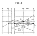
- the vertical axis direction indicates the rotational speeds of the respective rotating elements (respective gears) and the horizontal axis direction corresponds to the gear ratio of the rotating elements.
- the vertical axes correspond to the sun gear S1, the carrier CR1 and the ring gear R1 sequentially from the left side in FIG. 3 .
- the vertical axes correspond to the sun gear S3, the ring gear R2, the carrier CR2 and the sun gear S2 sequentially from the right side in FIG. 3 .
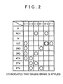
- the clutch C-1 and the one-way clutch F-1 are engaged as shown in FIG. 2 .
- the rotation of the carrier CR1 is input to the sun gear S3 via the clutch C-1, the rotation of the carrier CR1 being decelerated by the fixed sun gear S1 and the ring gear R1 of input rotation.
- the rotation of the carrier CR2 is restricted to one direction (normal rotation direction), i.e., the reverse rotation of the carrier CR2 is prevented resulting in a fixed state.
- the decelerated rotation input to the sun gear S3 is output to the ring gear R2 via the fixed carrier CR2, and the normal rotation as the forward first speed is output from the counter gear 11.
- the brake B-2 When the engine brake is applied (coasting), the brake B-2 is locked and the carrier CR2 is fixed, and in the form of preventing the normal rotation of the carrier CR2, the state of the forward first speed is maintained. At the forward first speed, the reverse rotation of the carrier CR2 is prevented by the one-way clutch F-1 and the normal rotation is made possible. Therefore, when the non-running range is changed to the running range, for example, the forward first speed can be smoothly achieved through automatic engaging of the one-way clutch F-1.
- the clutch C-1 and clutch C-3 are engaged as shown in FIG. 2 . Then, as shown in FIG. 1 and FIG. 3 , the rotation of the carrier CR1 decelerated by the fixed sun gear S1 and the ring gear R1 of input rotation is input to the sun gear S3 via the clutch C-1. When the clutch C-3 is engaged, the decelerated rotation of the carrier CR1 is input to the sun gear S2.
- the clutch C-2 is engaged and the brake B-1 is locked as shown in FIG. 2 .
- the input rotation is input to the carrier CR2 due to the engagement of the clutch C-2.
- the rotation of the sun gear S2 is fixed by the lock of the brake B-1. Due to the fixed sun gear S2, the input rotation of the carrier CR2 becomes accelerated rotation higher than the forward fifth speed and is output to the ring gear R2, and the normal rotation as the forward sixth speed is output from the counter gear 11.
- P (parking) range and N (neutral) range for example, the clutch C-1, the clutch C-2, and the clutch C-3 are released.
- disconnected state occurs between the carrier CR1 and the sun gear S2 and the sun gear S3, i.e., between the planetary gear SP and the planetary gear unit PU, and also the disconnected state occurs between the input shaft 10 and the carrier CR2.
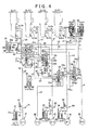
- a hydraulic control device 1 1 for the automatic transmission according to the present invention will now be described. First, the generating portions of line pressure, secondary pressure, modulator pressure and range pressure, whose illustration is omitted, in the hydraulic control device 1 1 are outlined. Since these generating portions of line pressure, secondary pressure, modulator pressure and range pressure are similar to those in an ordinary hydraulic control device for an automatic transmission and well known, they are briefly described.
- This hydraulic control device 1 1 includes an oil pump, a manual shift valve, a primary regulator valve, a secondary regulator valve, a solenoid modulator valve, and a linear solenoid valve SLT whose illustration is omitted.
- the hydraulic pressure generated by the oil pump is regulated to a line pressure P L while the discharge thereof is regulated by the primary regulator valve, based on a signal pressure P SLT of the linear solenoid valve SLT that is regulated and output in accordance with the throttle opening.
- This line pressure P L is supplied to the manual shift valve (range switching valve), the solenoid modulator valve, and a linear solenoid valve SLC3 describe later in detail.
- the line pressure P L supplied to the solenoid modulator valve is regulated to a modulator pressure P MOD that is made approximately constant by the valve. This modulator pressure P MOD is supplied as an original pressure to the linear solenoid valve SLT and solenoid valves S1 and S2 described later in detail.
- the pressure discharged from the primary regulator valve is regulated to a secondary pressure P SEC while the discharge thereof is further regulated by the secondary regulator valve, for example.
- the secondary pressure P SEC is supplied to a lubricating oil passage and an oil cooler, for example, and also to the torque converter 4 and is also used for controlling the lockup clutch 7.
- the manual shift valve (not illustrated) has a spool to be mechanically (or electrically) driven to a shift lever provided at the driver's seat (not illustrated), and the position of the spool is changed in accordance with the shift range (e.g. P, R, N, and D) selected by the shift lever, thereby setting the output state or non-output state (drain) of the input line pressure P L .
- the shift range e.g. P, R, N, and D
- the line pressure P L is output as a forward range pressure (D range pressure) P D .
- the R (reverse) range is set through the operation of the shift lever, the input port and a reverse range pressure output port are connected based on the position of the spool, and from the reverse range pressure output port, the line pressure P L is output as a reverse range pressure (R range pressure) P REV .
- the P range or the N range is set through the operation of the shift lever, cutoff is made between the input port and the forward range pressure output port or the reverse range pressure output port by the spool, and the forward range pressure output port or the reverse range pressure output port is connected to a drain port. That is, the D range pressure P D or the R range pressure P REV is drained, resulting in the non-output state.
- This hydraulic control device 1 1 includes four linear solenoid valves SLC1, SLC2, SLC3, and SLB1 to directly supply the output pressure regulated as an engaging pressure to five hydraulic servos in total: a hydraulic servo 41 of the clutch C-1, a hydraulic servo 42 of the clutch C-2, a hydraulic servo 43 of the clutch C-3, a hydraulic servo 44 of the brake B-1, and a hydraulic servo 45 of the brake B-2.
- the hydraulic control device 1 1 also includes the solenoid valve S1, the solenoid valve S2, a first clutch apply relay valve 21, a second clutch apply relay valve 22, a C-2 relay valve 23, and a B-2 relay valve 24, for example, as portions to achieve the limp-home function, and to switch the output pressure of the linear solenoid valve SLC2 to the hydraulic servo 42 of the clutch C-2 or the hydraulic servo 45 of the brake B-2.
- the forward range pressure output port (not illustrated) of the manual shift valve is connected so that the forward range pressure P D can be input.
- the reverse range pressure output port (not illustrated) of the manual shift valve is connected so that the reverse range pressure P REV can be input.
- the line pressure P L from the primary regulator valve (not illustrated) is input.
- the modulator pressure P MOD from the modulator valve (not illustrated) is input.
- the oil passage a1 is connected via an oil passage a2 to an input port 21e of the first clutch apply relay valve 21 to be detailed later, and is provided with a check valve 50 and an orifice 60.
- the oil passage a1 is connected to an accumulator 30 via an oil passage a3 and is also connected to the linear solenoid valve SLC1.
- the accumulator 30 has a case 30c, a piston 30b disposed inside the case 30c, a spring 30s to energize the piston 30b, and an oil chamber 30a formed between the case 30c and the piston 30b.
- the linear solenoid valve (first solenoid valve) SLC1 is of a normal close type that is placed in the non-output state during non-energizing, and has an input port SLC1a to input the forward range pressure P D via the oil passage a1 and an output port SLC1b to adjust the forward range pressure P D and output a controlled pressure (first operating hydraulic pressure) P SLC1 as an engaging pressure P C1 to the hydraulic servo 41.
- the linear solenoid valve SLC1 is so structured that it cuts off the input port SLC1a and the output port SLC1b to get into the non-output state during non-energizing, and during energizing based on a command value from a control unit (ECU) not illustrated, it increases the amount (amount of opening) to communicate the input port SLC1a with the output port SLC1b in accordance with the command value so that it can output the engaging pressure P C1 in accordance with the command value.
- the output port SLC1b of the linear solenoid valve SLC1 is connected to an input port 22c of the second clutch apply relay valve 22 described later via an oil passage b1.
- the linear solenoid valve (second solenoid valve) SLC2 is of a normal open type that gets into the output state during non-energizing, and has an input port SLC2a to input the forward range pressure P D via the oil passage a4, etc. and an output port SLC2b to adjust the forward range pressure P D and output a controlled pressure (second operating hydraulic pressure) P SLC2 as an engaging pressure P C2 (or engaging pressure P B2 ) to the hydraulic servo 42.
- the linear solenoid valve SLC2 gets into an output state with the input port SLC2a and the output port SLC2b communicated during non-energizing, and during energizing based on a command value from the control unit (ECU) not illustrated, the linear solenoid valve SLC2 decreases the amount (or reduce the amount of opening) to communicate the input port SLC2a with the output port SLC2b in accordance with the command value, that is, it is so structured that it can output the engaging pressure P C2 (or P B2 ) in accordance with the command value.
- the linear solenoid valve SLC2 is connected to an input port 22f of the second clutch apply relay valve 22 described later via an oil passage c1.
- the linear solenoid valve (third solenoid valve) SLC3 is of a normal open type that gets into the output state during non-energizing, and has an input port SLC3a to input the line pressure P L via the oil passage d, etc., and an output port SLC3b to adjust the line pressure P L and output a controlled pressure (third operating hydraulic pressure) P SLC3 as an engaging pressure P C3 to the hydraulic servo 43.
- the linear solenoid valve SLC3 gets into an output state with the input port SLC3a and the output port SLC3b communicated during non-energizing, and during energizing based on a command value from the control unit (ECU) not illustrated, the linear solenoid valve SLC3 decreases the amount (reduce the amount of opening) to communicate the input port SLC3a with the output port SLC3b in accordance with the command value so that it can output the engaging pressure P C3 in accordance with the command value.
- the output port SLC3b of the linear solenoid valve SLC3 is connected to the hydraulic servo 43 of the clutch C-3 via an oil passage e1.
- the oil passage e1 is provided with a check valve 53 and an orifice 63, and via an oil passage e2, an oil chamber 33a of a C-3 damper 33 is connected thereto. Since the C-3 damper 33 has the same structure as that of the accumulator 30 and is an ordinary damper, its detailed explanation is omitted.
- the linear solenoid valve SLB1 is of a normal close type that gets into the non-output state during non-energizing, and has an input port SLB1a to input the forward range pressure P D via the oil passage a5, etc. and an output port SLB1b to adjust the forward range pressure P D and output a controlled pressure P SLB1 as an engaging pressure P B1 to the hydraulic servo 44.
- the linear solenoid valve SLB1 cuts off the input port SLB1a and the output port SLB1b to get into the non-output state during non-energizing, and during energizing based on a command value from the control unit (ECU) not illustrated, it increases the amount (amount of opening) to communicate the input port SLB1a with the output port SLB1b in accordance with the command value so that it can output the engaging pressure P B1 in accordance with the command value.
- the output port SLB1b of the linear solenoid valve SLB1 is connected to the hydraulic servo 44 of the brake B-1 via an oil passage f1.
- the oil passage f1 is provided with a check valve 54 and an orifice 64, and via an oil passage f2, an oil chamber 34a of a B-1 damper 34 is connected thereto.
- the solenoid valve (fourth solenoid valve) S1 is of a normal open type that gets into the output state during non-energizing, and has an input port S1a to input the modulator pressure P MOD via the oil passages g1 and an oil passage g2, and an output port S1b to output the modulator pressure P MOD approximately as it is as a signal pressure P S1 during non-energizing (i.e., during OFF).
- the output port S1b is connected to an oil chamber 21a of the first clutch apply relay valve 21 via an oil passages h1, h2. Further, via oil passages h1, h3, the output port S1b is connected to an oil chamber 22a of the second clutch apply relay valve 22, and via an oil passage h4, it is connected to an input port 24c of the B-2 relay valve 24.
- the solenoid valve S2 is of a normal close type that gets into the non-output state during non-energizing, and has an input port S2a to input the modulator pressure P MOD via the oil passages g1 and an oil passage g3, and an output port S2b to output the modulator pressure P MOD approximately as it is as a signal pressure P S2 during energizing (i.e., during ON).
- the output port S2b is connected to an oil chamber 24a of the B-2 relay valve via an oil passage i.
- the first clutch apply relay valve (preliminary shift speed switching valve) 21 has two spools 21p and 21 q, a spring 21s to bias the spool 21p upward in the figure, and a spring 21t to bias the spools 21p and 21q in a direction to separate them, and also has the oil chamber 21a at the upper part in the figure of the spool 21 q, an oil chamber 21d at the lower part in the figure of the spool 21p, an oil chamber 21c between the spools 21p and 21q, and an oil chamber 21b formed due to a diameter difference (difference in pressure receiving area) of the land portion of the spool 21q, and furthermore, it has the input port 21e, an input port 21f, an input port 21g, an input port 21h, an output port 21i, an output port 21j, and a drain port EX.
- the first clutch apply relay valve 21 is so structured that when the spools 21p, 21q are set to the left half position (high speed side position), the input port 21e and the output port 21j are communicated and the input port 21e and the output port 21i are disconnected, and when they are set to the right half position (low speed side position), the input port 21e and the output port 21i are communicated and the output port 21j and the drain port EX are communicated.
- the spool 21p is set to the left half position
- the input port 21h is disconnected
- the spool 21q is set to the right half position
- the input port 21 g is disconnected.
- the oil chamber 21a is connected to the output port S1b of the solenoid valve S1 via the oil passages h1, h2, and the oil chamber 21b is connected to an output port 22i of the second clutch apply relay valve 22 described later via an oil passage b4 from the input port 21f.
- the forward range pressure P D is input via the oil passages a1, a2.
- the output port 21j that is communicated with the input port 21e when the spool 21p is at the left half position is connected to an input port 22h of the second clutch apply relay valve 22 via an oil passage j.
- the output port 21i that is communicated with the input port 21e when the spool 21p is at the right half position is connected to the input port 21 g via oil passages k1, k2 and to the input port 21h via oil passages k1, k2, k3. That is, the output port 21i is connected to the oil chamber 21c regardless of the position of the spools 21p, 21q.
- the output port 21i is connected to an input port 22e of the second clutch apply relay valve 22 described later via the oil passage k1.
- an output port 23c of the C-2 relay valve 23 is connected via an oil passage c5, and the oil passage c5 is provided with a check valve 55 and an orifice 65.
- the second clutch apply relay valve (hydraulic pressure supply switching valve) 22 has a spool 22p and a spring 22s to bias the spool 22p upward in the figure and also has the oil chamber 22a at the upper part in the figure of the spool 22p and an oil chamber 22b at the lower part in the figure of the spool 22p. Further, the second clutch apply relay valve 22 has the input port 22c, an output port 22d, the input port 22e, the input port 22f, an output port 22g, the input port 22h, and the output port 22i.
- the second clutch apply relay valve 22 is so structured that when the spool 22p is set to the left half position (normal position), the input port 22c and the output port 22d and the output port 22i are communicated and the input port 22f and the output port 22g are communicated, and the input port 22e and the input port 22h are disconnected; and when the spool 22p is set to the right half position (failure position), the input port 22e and the output port 22d are communicated and the input port 22h and the output port 22g are communicated, and the input port 22c and the output port 22i and the input port 22f are disconnected.
- the oil chamber 22a is connected to the output port S1b of the solenoid valve S1 via the oil passages h1, h3, and connected to the input port 24c of the B-2 relay valve 24 described later via the oil passage h4.
- the input port 22c is connected to the output port SLC1b of the linear solenoid valve SLC1 via the oil passage b1.
- the output port 22d that is communicated with the input port 22c when the spool 22p is set to the left half position is connected to the hydraulic servo 41 of the clutch C-1 via an oil passage b2.
- the oil passage b2 is provided with a check valve 51 and an orifice 61, and via an oil passage b3, an oil chamber 31a of a C-1 damper 31 is connected thereto.
- the output port 22i that is communicated with the input port 22c when the spool 22p is set to the left half position is connected to the input port 21f of the first clutch apply relay valve 21 via the oil passage b4, and is connected to the oil chamber 22b via oil passages b4, b5.
- the input port 22f is connected to the output port SLC2b of the linear solenoid valve SLC2 via the oil passage c1
- the input port 22h is connected to the output port 21j of the first clutch apply relay valve 21 via the oil passage (second oil passage) j.
- the output port 22g that is communicated with the input port 22f when the spool 22p is set to the left half position and communicated with the input port 22h when the spool 22p is set to the right half position is connected to an input port 23b of the C-2 relay valve 23 described later via an oil passage c2.
- the oil passage c2 is provided with a check valve 52 and an orifice 62 and via an oil passage c4, an oil chamber 32a of a C2-B2 damper 32 is connected thereto.
- the C-2 relay valve 23 has a spool 23p and a spring 23s to bias the spool 23p upward in the figure, and also has an oil chamber 23a at the upper part in the figure of the spool 23p, and furthermore, it has the input port 23b, the output port 23c, an output port 23d, an output port 23e and a drain port EX.
- the C-2 relay valve 23 is so structured that, when the spool 23p is set to the left half position, the input port 23b and the output port 23c and the output port 23e are communicated and the output port 23d and the drain port EX are communicated, and when the spool 23p is set to the right half position, the input port 23b and the output port 23d are communicated and the output port 23c and the output port 23e and the drain port EX are communicated.
- the oil chamber 23a is connected to an output port 24b of the B-2 relay valve 24 described later via an oil passage h5.
- the input port 23b is connected to the output port 22g of the second clutch apply relay valve 22 via the oil passage c2.
- the output port 23e that is communicated with the input port 23b when the spool 23p is at the left half position is connected to the hydraulic servo 42 of the clutch C-2 via an oil passage c3.
- the output port 23c that is communicated with the input port 23b when the spool 23p is at the left half position is connected to the oil chamber 21 d of the first clutch apply relay valve 21 via the oil passage c5.
- the oil passage c5 is provided with the check valve 55 and the orifice 65.
- the output port 23d that is communicated with the input port 23b when the spool 23p is at the right half position is connected to an input port 24e of the B-2 relay valve 24 via an oil passage m.
- the B-2 relay valve 24 has a spool 24p, and a spring 24s to bias the spool 24p upward in the figure, and also has the oil chamber 24a at the upper part in the figure of the spool 24p. Further, the B-2 relay valve 24 has the output port 24b, the input port 24c, an input port 24d, the input port 24e, an output port 24f, an output port 24g, and a drain port EX.
- the B-2 relay valve 24 is so structured that, when the spool 24p is set to the left half position, the input port 24d and the output port 24f and the output port 24g are communicated and the output port 24b and the drain port EX are communicated, and the input port 24c is disconnected; and when the spool 24p is set to the right half position, the input port 24c and the output port 24b are communicated and the input port 24e and the output port 24g are communicated, and the input port 24d and the drain port EX are disconnected.
- the oil chamber 24a is connected to the output port S2b of the solenoid valve S2 via an oil passage i.
- the input port 24d is connected to the reverse range pressure output port (not illustrated) of the manual shift valve to which the reverse range pressure P REV is output via an oil passage I.
- the input port 24e is connected to the output port 23d of the C-2 relay valve 23 via the oil passage m.
- the output port 24g that is communicated with the input port 24d when the spool 24p is at the left half position and that is communicated with the input port 24e when the spool 24p is at the right half position is connected to the hydraulic servo 45 of the brake B-2 via an oil passage n.
- the hydraulic servo 45 of the brake B-2 is connected to the reverse range pressure output port (not illustrated) of the manual shift valve, or to the output port SLC2b of the linear solenoid valve SLC2.
- the input port 24c is connected to the output port S1b of the solenoid valve S1 via the oil passage h4, the oil chamber 22a of the second clutch apply relay valve 22, and the oil passages h1, h3.
- the output port 24b is communicated with the input port 24c when the spool 24p is at the right half position is connected to the oil chamber 23a of the C-2 relay valve 23 via the oil passage h5.
- the output port 24f that is communicated with the input port 24d when the spool 24p is at the left half position is connected to the oil chamber of the primary regulator valve via an oil passage (not illustrated), and the line pressure P L is raised during reverse travel by having the reverse range pressure P REV work on the primary regulator valve.
- the hydraulic control for this hydraulic control device 1 1 is started. If the selected position of the shift lever is P range or N range, the normal type linear solenoid valve SLC2, the linear solenoid valve SLC3 and the solenoid valve S1 are energized by electric command of the control unit not illustrated and the respective input ports and output ports are disconnected.
- a hydraulic pressure is generated by the rotation of the oil pump (not illustrated) based on the engine rotation, and the hydraulic pressure is regulated to a line pressure P L and a modulator pressure P MOD , respectively, by the primary regulator valve and the solenoid modulator valve and output, and the line pressure P L is input to the input port of the manual shift valve not illustrated and to the input port SLC3a of the linear solenoid valve SLC3 via the oil passage d, and the modulator pressure P MOD is input to the input ports S1a, S2a of the solenoid valves S1, S2 via the oil passages g1, g2, g3.
- a forward range pressure P D is output to the oil passages a1, a4, a5 from the forward range pressure output port of the manual shift valve.
- the forward range pressure P D is input to the linear solenoid valve SLC1 via the oil passage a1, the linear solenoid valve SLC2 via the oil passage a4, the linear solenoid valve SLB1 via the oil passage a5, and the first clutch apply relay valve 21 via the oil passages a1, a2, respectively.
- the oil passage a1 is provided with the check valve 50 and the orifice 60, and since the check valve 50 is opened by the forward range pressure P D , the supply of the forward range pressure P D to the linear solenoid valve SLC1 becomes quicker than in discharge.
- the forward range pressure P D supplied to the oil passage a1 is input to the oil chamber 30a of the accumulator 30 via the oil passage a3.
- the accumulator 30 accumulates the forward range pressure P D to be supplied to the linear solenoid valve SLC1.
- the first clutch apply relay valve 21 where the forward range pressure P D is input from the oil passage a2 is shifted to the left half position by the biasing force of the spring 21s at the beginning of switching to D range (at the beginning of N-D shifting) because the signal pressure P S1 is not output with the solenoid valve S1 set to ON, and the forward range pressure P D is output to the oil passage j from the output port 21j.
- the signal pressure P S1 is not output with the solenoid valve S1 set to ON
- the input port 22h is disconnected in the second clutch apply relay valve 22, which is shifted to the left half position by the biasing force of the spring 22s.
- the linear solenoid valve SLC1 is switched ON by electrical control of the control unit, and the forward range pressure P D input to the input port SLC1a is regulated and controlled, and the controlled pressure P SLC1 is gradually increased as the engaging pressure P C1 and output from the output port SLC1b.
- the controlled pressure P SLC1 (engaging pressure P C1 ) is input to the input port 22c of the second clutch apply relay valve 22 via the oil passage b1.
- the second clutch apply relay valve 22 set to the left half position outputs the controlled pressure P SLC1 input to the input port 22c, from the output port 22i and also from the output port 22d.
- the controlled pressure P SLC1 output from the output port 22i is input to the oil chamber 22b via the oil passages b4, b5, and locks the second clutch apply relay valve 22 to the left half position, and is input to the oil chamber 21b of the first clutch apply relay valve 21 via the oil passage b4, and pushes the spools 21p, 21 q to the lower part in the figure against the biasing force of the spring 21s, and switches the first clutch apply relay valve 21 to the right half position.
- the forward range pressure P D input from the input port 21 e is output as a first preliminary hydraulic pressure P DC1 from the output port 21i and is input to the oil chamber 21c via the oil passages k1, k2, k3 and the input port 21h
- the spool 21q is switched to the upper part in the figure by means of the hydraulic pressure working on the oil chamber 21c and the biasing force of the spring 21t.
- the controlled pressure P SLC1 input to the input port 22c of the second clutch apply relay valve 22 from the linear solenoid valve SLC1, as described above, is output as the engaging pressure P C1 to the hydraulic servo 41 via the oil passage b2 from the output port 22d, and the clutch C-1 is engaged.
- the forward first speed is achieved.
- the oil passage b2 is provided with the check valve 51 and the orifice 61.
- the check valve 51 is closed and the hydraulic pressure is slowly supplied only through the orifice 61.
- the check valve 51 is opened so that the engaging pressure P C1 is quickly discharged compared to when being supplied.
- the engaging pressure P C1 supplied to the oil passage b2 is input to the oil chamber 31a of the C-1 damper 31 via the oil passage b3.
- the C-1 damper 31 prevents pulsation of the engaging pressure P C1 supplied to and discharged from the hydraulic servo 41, and absorbs a surge pressure (rapid fluctuating pressure).
- the solenoid valve S2 is switched ON and the solenoid valve S1 is switched OFF by an electric command from the control unit and the linear solenoid valve SLC2 is controlled in pressure.
- the solenoid valve S2 is switched ON, the modulator pressure P MOD input to the input port S2a via oil passages g1, g3 is output as a signal pressure P S2 from the output port S2b and input to the oil chamber 24a of the B-2 relay valve 24 via the oil passage i.
- the spool 24p is switched to the lower part in the figure against the biasing force of the spring 24s, and the B-2 relay valve 24 is set to the right half position.
- the modulator pressure P MOD input to the input port S1a via oil passages g1, g2 is output as a signal pressure P S1 from the output port S1b, and is input to the oil chamber 21a of the first clutch apply relay valve 21 via the oil passages h1, h2, the oil chamber 22a of the second clutch apply relay valve 22 via the oil passages h1, h3, and the input port 24c of the B-2 relay valve 24 via the oil passage h4, and also to the oil chamber 23a of the C-2 relay valve 23 via the oil passage h5 from the output port 24b of the B-2 relay valve 24 set to the right half position.
- the spool 23p is switched to the lower part in the figure against the biasing force of the spring 23s by means of the signal pressure P S1 input to the oil chamber 23a, and the C-2 relay valve 23 is set to the right half position.
- the spool 21q is switched to the lower part in the figure because of the signal pressure P S1 input to the oil chamber 2 1 a and the first clutch apply relay valve 21 is set to the right half position, the spool 21p remains in the right half position as in the forward first speed without being specifically affected.
- the controlled pressure P SLC2 is input to the input port 22f of the second clutch apply relay valve 22 locked to the left half position via the oil passage c1, and is output as the engaging pressure P B2 to the oil passage c2 from the output port 22g.
- the engaging pressure P B2 output to the oil passage c2 is input to the input port 23b of the C-2 relay valve 23 set to the right half position, and is output from the output port 23d. Furthermore, the engaging pressure P B2 is input to the input port 24e of the B-2 relay valve 24 set to the right half position via the oil passage m, and is output from the output port 24g, and is input to the hydraulic servo 45 via the oil passage n, and the brake B-2 is locked.
- the engine brake of the forward first speed is achieved.
- the oil passage c2 is provided with the check valve 52 and the orifice 62, and when the engaging pressure P B2 is supplied to the hydraulic servo 45 of the brake B-2, the check valve 52 is closed and the hydraulic pressure is slowly supplied through the orifice 62 only, and at the time of discharging to be described later, the check valve 52 is opened and the hydraulic pressure in the oil passage c2 is quickly discharged.
- the engaging pressure P B2 supplied to the oil passage c2 is input to the oil chamber 32a of the C2-B2 damper 32 via the oil passage c4, and the C2-B2 damper 32 prevents pulsating of the engaging pressure P B2 supplied to and discharged from the hydraulic servo 45, absorbs a surge pressure (rapid fluctuating pressure), etc.
- the solenoid valve S2 is set to OFF and the solenoid valve S1 to ON. Further, the linear solenoid valve SLC2 is closed in the form of ON (energizing), and the controlled pressure P SLC2 as the engaging pressure P B2 is set to 0 and drained.
- the engaging pressure P B2 of the hydraulic servo 45 of the brake B-2 is discharged through the drain port of the manual shift valve via the input port 24d, an oil passage 1, and the reverse range pressure output port (not illustrated) of the manual shift valve, because the B-2 relay valve 24 is switched to the left half position when the solenoid valve S2 is set to OFF.
- the control unit determines whether the forward second speed is judged from the state of the forward first speed by the control unit, in a state where the solenoid valve S1 is set to ON and the solenoid valve S2 to OFF by the electrical command from the control unit as in the case of the forward first speed (except for engine brake), the pressure regulation control of the linear solenoid valve SLBlis performed while the pressure regulated state of the linear solenoid valve SLC1 is maintained.
- the oil passage f1 is provided with the check valve 54 and the orifice 64.
- the check valve 54 is closed and the hydraulic pressure is slowly supplied only through the orifice 64.
- the check valve 54 is opened so that the hydraulic pressure is quickly discharged compared to when being supplied.
- the engaging pressure P B1 supplied to the oil passage f1 is input to the oil chamber 34a of the B-1 damper 34 via the oil passage f2.
- the B-1 damper 34 prevents pulsation of the engaging pressure P B1 supplied to and discharged from the hydraulic servo 44, and absorbs the surge pressure (rapid fluctuating pressure).
- the linear solenoid valve SLB1 is closed in the form of OFF and the pressure regulation control of the linear solenoid valve SLC3 is performed, while the pressure regulated state of the linear solenoid valve SLC1 is maintained.
- the brake B-1 is release-controlled. More specifically, the engaging pressure P B1 (controlled pressure P SLB1 ) of the hydraulic servo 44 of the brake B-1 is discharge-controlled through the drain port EX of the linear solenoid valve SLB1 via the oil passage f1, and the brake B-1 is released.
- the linear solenoid valve SLC3 is controlled in pressure from the state of being closed so that the controlled pressure P SLC3 becomes 0 after ON (energizing).
- the controlled pressure P SLC3 is output as the engaging pressure P C3 from the output port SLC3b, and is input to the hydraulic servo 43 via the oil passage e1, and the clutch C-3 is engaged.
- the forward third speed is achieved.
- the oil passage e1 is provided with the check valve 53 and the orifice 63.
- the check valve 53 is closed and the hydraulic pressure is slowly supplied only through the orifice 63.
- the check valve 53 is opened so that the hydraulic pressure is quickly discharged compared to when being supplied.
- the engaging pressure P C3 supplied to the oil passage e1 is input to the oil chamber 33a of the C-3 damper 33 via the oil passage e2.
- the C-3 damper 33 prevents pulsation of the engaging pressure P C3 supplied to and discharged from the hydraulic servo 43, and absorbs the surge pressure (rapid fluctuating pressure).
- the linear solenoid valve SLC3 is closed in the form of OFF and the pressure regulation control of the linear solenoid valve SLC2 is performed, while the pressure regulated state of the linear solenoid valve SLC1 is maintained.
- the clutch C-3 is release-controlled. More specifically, the engaging pressure P C3 (controlled pressure P SLC3 ) of the hydraulic servo 43 of the clutch C-3 is discharge-controlled from the drain port EX of the linear solenoid valve SLC3 via the oil passage e1, and the clutch C-3 is released.
- the linear solenoid valve SLC2 is controlled in pressure from the state of being closed so that the controlled pressure P SLC2 becomes 0 after ON (energizing).
- the controlled pressure P SLC2 is output as the engaging pressure P C2 from the output port SLC2b, and is input to the input port 22f of the second clutch apply relay valve 22 via the oil passage c1.
- the second clutch apply relay valve 22 Since the second clutch apply relay valve 22, with the solenoid valve S1 set to ON and the signal pressure P S1 not input to the oil chamber 22a, is locked to the left half position by the engaging pressure P C1 input to the oil chamber 22b, the controlled pressure P SLC2 (engaging pressure P C2 ) input to the input port 22f is output from the output port 22g as the engaging pressure P C2 .
- the engaging pressure P C2 output from the output port 22g is input to the input port 23b of the C-2 relay valve 23 via the oil passage c2.
- the engaging pressure P C2 input to the input port 23b is output from the output port 23c, and is also output from the output port 23e.
- the engaging pressure P C2 output from the output port 23c is input to the oil chamber 21d of the first clutch apply relay valve 21 via the oil passage c5, and the spool 21p of the first clutch apply relay valve 21 is switched to the left half position and locked by the engaging pressure P C2 , together with the biasing force of the spring 21s.
- the forward range pressure P D input to the input port 22e via the oil passage k1 is switched from the output port 21i to output port 21j, and is output as a second preliminary hydraulic pressure P DC2 to the oil passage j, however, blocked by the input port 22h of the second clutch apply relay valve 22. Since the first preliminary hydraulic pressure P DC1 (forward range pressure P D ) supplied to the oil passage k1 is blocked, the supply of the forward range pressure P D as the lock pressure to the oil chamber 21c via the oil passages k2, k3 is released.
- the oil passage c5 is provided with the check valve 55 and the orifice 65.
- the check valve 55 is closed, and the hydraulic pressure is slowly supplied only through the orifice 65.
- the check valve 55 is opened so that the hydraulic pressure is discharged more quickly than when being supplied.
- the engaging pressure P C2 output from the output port 23e of the C-2 relay valve 23 is input to the hydraulic servo 42 via the oil passage c3, and the clutch C-2 is engaged.
- the forward fourth speed is achieved.
- the oil passage c2 is provided with the check valve 52 and the orifice 62.
- the check valve 52 is closed and the hydraulic pressure is slowly supplied only through the orifice 62.
- the check valve 52 is opened so that the hydraulic pressure is discharged more quickly than when being supplied.
- the engaging pressure P C2 supplied to the oil passage c2 is input to the oil chamber 32a of the C2-B2 damper 32 via the oil passage c4.
- the C2-B2 damper 32 prevents pulsation of the engaging pressure P C2 supplied to and discharged from the hydraulic servo 42, and absorbs the surge pressure (rapid fluctuating pressure).
- the linear solenoid valve SLC1 is closed in the form of OFF, and the pressure regulation control of the linear solenoid valve SLC3 is performed.
- the clutch C-1 is release-controlled. More specifically, the engaging pressure P C1 (controlled pressure P SLC1 ) of the hydraulic servo 41 of the clutch C-1 is discharge-controlled from the drain port EX of the linear solenoid valve SLC1 via the oil passages b1, b2, and the clutch C-1 is released.
- the linear solenoid valve SLC3 is controlled in pressure from the state of being closed so that the controlled pressure P SLC3 becomes 0 after ON (energizing).
- the controlled pressure P SLC3 is output as the engaging pressure P C3 from the output port SLC3b, and is input to the hydraulic servo 43 via the oil passage e1, and the clutch C-3 is engaged.
- the forward fifth speed is achieved.
- the linear solenoid valve SLC3 is closed in the form of ON (energizing) and the pressure regulation control of the linear solenoid valve SLB1 is performed, while the pressure regulated state of the linear solenoid valve SLC2 is maintained.
- the clutch C-3 is release-controlled. More specifically, the engaging pressure P C3 (controlled pressure P SLC3 ) of the hydraulic servo 43 of the clutch C-3 is discharge-controlled from the drain port EX of the linear solenoid valve SLC3 via the oil passage e1, and the clutch C-3 is released.
- the linear solenoid valve SLB1 is switched ON (energizing) and controlled in pressure, from the state of being closed so that the controlled pressure P SLB1 becomes 0 after OFF.
- the controlled pressure P SLB1 is output as the engaging pressure P B1 from the output port SLB1b, and is input to the hydraulic servo 44 via the oil passage f1, and the brake B-1 is engaged.
- the forward sixth speed is achieved.
- the forward range pressure output port of the manual shift valve is disconnected with the input port and communicated with the drain port, that is, the forward range pressure P D is drained.
- a shift lever sensor (not illustrated) detects that the shift lever is in the N range position, and if the N range is judged by the control unit in accordance with the shift lever position, the linear solenoid valve SLC2 and the linear solenoid valve SLC3 are set to ON (energized) and the linear solenoid valve SLB1 to OFF, and these controlled pressures P SLC2 , P SLC3 , and P SLB1 are drained to 0 (non-output state). That is, the hydraulic pressures of the respective hydraulic servos 42, 43, 44 and 45 are drained, and the clutch C-2, the clutch C-3, the brake B-1 and the brake B-2 are released.
- the solenoid valve S1 is maintained in the ON (energized) state, and the solenoid valve S2 is maintained in the OFF state. That is, signal pressures P S1 , P S2 are not output from both the solenoid valves S1 and S2.
- the linear solenoid valve SLC1 performs the pressure regulation control such that the controlled pressure P SLC1 is gradually reduced and finally the controlled pressure P SLC1 is drained to 0 (non-output state), thereby slowly releasing the clutch C-1.
- this clutch C-1 is also released, all clutch brakes of the automatic transmission 3 are released, resulting in a neutral state.
- the accumulator 30 connected to the input port SLC1a of the linear solenoid valve SLC1 via the oil passage a3, etc. maintains the pressure by releasing a hydraulic pressure accumulated during the D range, to the oil passages a1, a3 on the side of the linear solenoid valve SLC1 rather than the orifice 60.
- the slow release control of the clutch C-1 by the linear solenoid valve SLC1 is realized. This prevents the release shock from occurring when the D-N shift operation is performed from the forward first speed state.
- the reverse range pressure P REV is output from the reverse range pressure output port of the manual shift valve, and the reverse range pressure P REV is input to the input port 24d of the B-2 relay valve 24 via the oil passage 1, etc.
- the solenoid valve S1 is set to ON (energized) and maintained, and the solenoid valve S2 is set to OFF and maintained. That is, since the signal pressure P S2 is not output, the B-2 relay valve 24 is maintained at the left half position by the biasing force of the spring 24s. By this, the reverse range pressure P REV input to the input port 24c is supplied to the hydraulic servo 45 of the brake B-2 via the output port 24g and the oil passage n, and the brake B-2 is engaged.
- the pressure regulation control is performed by the control unit so that the linear solenoid valve SLC3 gradually outputs the controlled pressure P SLC3 , which is output as the engaging pressure P C3 from the output port SLC3b and is input to the hydraulic servo 43 via the oil passage e1. That is, the clutch C-3 is slowly engaged. Thus, together with the locking of the brake B-2, the reverse first speed is achieved.
- the solenoid valve S2 is switched ON by the control unit, and the ON state (energized state) of the linear solenoid valve SLC3 is maintained. That is, the R range pressure P REV is blocked by the B-2 relay valve 24 so that it will not be supplied to the hydraulic servo 45 of the brake B-2, and the engaging pressure P C3 (controlled pressure P SLC3 ) is not supplied to the hydraulic servo 43 of the clutch C-3.
- a so-called reverse inhibit function works, and the reverse first speed is prevented from being achieved.
- the first clutch apply relay valve 21 During running at the forward first speed to the forward third speed when normal, the first clutch apply relay valve 21 has the spool 21p locked to the right half position by the first preliminary hydraulic pressure P DC1 input to the oil chamber 2 1 c. For this reason, the first preliminary hydraulic pressure P DC1 is input to the input port 22e of the second clutch apply relay valve 22 via the oil passage k1 and is blocked by the second clutch apply relay valve 22 set to the left half position (normal position).
- the second clutch apply relay valve 22 is switched to the right half position (failure position) when the signal pressure P S1 output from the solenoid valve S1 is input to the oil chamber 22a via the oil passages h1, h3, and the first preliminary hydraulic pressure P DC1 input to the input port 22e is output from the output port 22d and input to the hydraulic servo 41 via the oil passage b2, and the clutch C-1 is engaged.
- the pressure P SLC2 (engaging pressure P C2 ) output from the linear solenoid valve SLC2 of the normal open type is blocked by the input port 22f of the second clutch apply relay valve 22 switched to the right half position.
- the line pressure P L input to the input port SLC3a is, approximately as it is, output as the engaging pressure P C3 from the output port SLC3b and input to the hydraulic servo 43 via the oil passage e1, and the clutch C-3 is engaged.
- the clutch C-1 and the clutch C-3 are engaged and the forward third speed is achieved (see FIG. 2 ). That is, the running state at the forward third speed is secured when the all-off failure occurs during the running at the forward first speed to the forward third speed.
- the controlled pressure P SLC2 (engaging pressure P C2 ) of the clutch C-2 is input to the oil chamber 21d of the first clutch apply relay valve 21 via the oil passage c1, the second clutch apply relay valve 22, the oil passage c2, the C-2 relay valve 23, and the oil passage c5, and the spools 21p, 21 q are locked to the left half position. Therefore, the second preliminary hydraulic pressure P DC2 output from the output port 21j is input to the input port 22h of the second clutch apply relay valve 22 via the oil passage j, and blocked by the second clutch apply relay valve 22 set to the left half position.
- the second clutch apply relay valve 22 is switched to the right half position when the signal pressure P S1 output from the solenoid valve S1 is input to the oil chamber 22a via the oil passages h1, h3, and the solenoid valve S2 becomes OFF and the B-2 relay valve 24 is not switched and is maintained at the left half position. Therefore, the oil passage h4 is blocked, and since the signal pressure P S1 of the solenoid valve S1 is not output to the oil passage h5, the C-2 relay valve 23 is not switched and is maintained at the left half position.
- the second preliminary hydraulic pressure P DC2 input to the input port 22h of the second clutch apply relay valve 22 is output from the output port 22g and input to the hydraulic servo 42 via the hydraulic pressure c2, the C-2 relay valve 23, and the oil passage c3, and the clutch C-2 is engaged.
- the pressure P SLC2 (engaging pressure P C2 ) output from the linear solenoid valve SLC2 of the normal open type is blocked by the input port 22f of the second clutch apply relay valve 22 switched to the right half position.
- the first clutch apply relay valve 21 is continuously locked to the left half position.
- the linear solenoid valve SLC3 With the linear solenoid valve SLC3 normally opened, the line pressure P L input to the input port SLC3a is, approximately as it is, output as the engaging pressure P C3 from the output port SLC3b and input to the hydraulic servo 43 via the oil passage e1, and the clutch C-3 is engaged.
- the clutch C-2 and the clutch C-3 are engaged and the forward fifth speed is achieved (see FIG. 2 ). That is, the running state at the forward fifth speed is secured when the all-off failure occurs during running at the forward fourth speed to the forward sixth speed.
- the manual shift lever not illustrated stops the output of the forward range pressure P D and drains.
- the forward range pressure P D to the linear solenoid valve SLC2 normally opened and to the input port 21e of the first clutch apply relay valve 21 is drained.
- the second preliminary hydraulic pressure P DC2 to the oil chamber 21d input via the oil passages j, c2, c5 is drained, and the lock by the second preliminary hydraulic pressure P DC2 is unlocked.
- the solenoid valve S1 normally opened, the signal pressure P S1 is continuously output. Therefore, the spools 21p, 21 q of the first clutch apply relay valve 21 are switched to the right half position by the signal pressure P S1 input to the oil chamber 21a.
- the forward range pressure P D is output from the manual shift valve.
- the forward range pressure P D is input to the input port 21e of the first clutch apply relay valve 21 switched to the right half position, and it is output as the first preliminary hydraulic pressure P DC1 from the output port 21i to the oil passage k1, and input to the hydraulic servo 41 of the clutch C-1 via the input port 22e and the output port 22d of the second clutch apply relay valve 22 at the right half position, and the oil passage b2, and the clutch C-1 is engaged. That is, the same state as that at the all-off failure during the running at the forward first speed to the forward third speed occurs, and the forward third speed is secured. This enables restarting of the vehicle even after the vehicle temporarily stops after the all-off failure, and the limp-home function is secured.
- the clutches C-1, C-2, C-3 are controlled such that they are freely engaged by the controlled pressures P SLC1 , P SLC2 , P SLC3 of the linear solenoid valves SLC1, SLC2, SLC3, respectively, during normal running.
- the controlled pressure P SLC3 of the linear solenoid valve SLC3 is supplied to the hydraulic servo 43 of the clutch C-3, and the output state of the first preliminary hydraulic pressure P DC1 or the second preliminary hydraulic pressure P DC2 is switched based on the engaged state of the clutch C-2 by the first clutch apply relay valve 21.
- the first preliminary hydraulic pressure P DC1 or the second preliminary hydraulic pressure P DC2 can be supplied to the hydraulic servo 41 of the clutch C-1 or the hydraulic servo 42 of the clutch C-2, respectively.
- this can achieve the forward third speed or the forward fifth speed in accordance with the shift speed before the occurrence of the all-off failure, with a structure equipped with only two valves, i.e., the first clutch apply relay valve 21 and the second clutch apply relay valve 22, making it possible to achieve compactness and cost reduction.
- the controlled pressure P SLC2 of the linear solenoid valve SLC2 is supplied as the engaging pressure P C2 to the hydraulic servo 42 of the clutch C-2, and also supplied to the oil chamber 21d of the first clutch apply relay valve 21.
- the spools 21p, 21q of the first clutch apply relay valve 21 are switched to the left half position.
- the linear solenoid valve SLC2 is formed by a normal close type and when the all-off failure occurs at the forward fourth speed to the forward sixth speed, the output port SLC2b of the linear solenoid valve SLC2 is closed and the controlled pressure P SLC2 becomes 0.
- the signal pressure P S1 is output from the solenoid valve S1 formed by a normal open type, and input to the oil chamber 21 a of the first clutch apply relay valve 21.
- the signal pressure P S1 of the solenoid valve S1 is also input to the oil chamber 22a of the second clutch apply relay valve 22, for example, if the second clutch apply relay valve 22 is switched to the right half position before the first clutch apply relay valve 21 is switched, the second preliminary hydraulic pressure P DC2 supplied to the oil passage j is supplied to the hydraulic servo 42 of the clutch C-2 via the oil passages c2, c3 and also to the oil chamber 21d of the first clutch apply relay valve 21 via the oil passage c5. Accordingly, the first clutch apply relay valve 21 is maintained at the left half position (position on high speed side), thus achieving the forward fifth speed as described above, posing no problem.
- the second clutch apply relay valve 22 is switched later than the switching of the first clutch apply relay valve 21, the controlled pressure P SLC2 of the oil chamber 21d of the first clutch apply relay valve 21 becomes 0, and the signal pressure P S1 of the solenoid valve S1 is input to the oil chamber 21a.
- the first clutch apply relay valve 21 is switched to the right half position (position on low speed side), thus forming the forward third speed as described above, resulting in down-shifting.
- the linear solenoid valve SLC2 is formed by the normal open type. Accordingly, even if the all-off failure occurs in the forward fourth speed to the forward sixth speed, the output port SLC2b of the linear solenoid valve SLC2 opens, and the controlled pressure P SLC2 is output approximately equivalent to the forward range pressure P D , that is, the controlled pressure P SLC2 input to the oil chamber 21d of the first clutch apply relay valve 21 does not decrease.
- the first clutch apply relay valve 21 is so structured that the forward range pressure P D (first preliminary hydraulic pressure P DC1 ) that has passed through the valve when at the right half position (position on low speed side) is input to the oil chamber 21c and it is locked to the right half position, and even if the controlled pressure P SLC1 of the linear solenoid valve SLC1 decreases due to a pressure regulating operation, etc., it can be maintained at the right half position.
- P D first preliminary hydraulic pressure P DC1
- FIG. 5 A second embodiment in which the first embodiment is partially changed will now be described with reference to FIG. 5 .
- the second embodiment only changed portions from the first embodiment are described and the same portions are attached with the same numerals and the description is omitted.
- the illustration of the linear solenoid valve SLB1, the hydraulic servos 44, 45 of the brakes B-1, B-2, the solenoid valve S2, the C-2 relay valve 23, and the B-2 relay valve 24, etc. is omitted, although the hydraulic control device 1 2 includes them.
- the structures of a first clutch apply relay valve (preliminary shift speed switching valve) 121 and a second clutch apply relay valve (hydraulic pressure supply switching valve) 122 are changed in comparison with the hydraulic control device 1 1 according to the first embodiment.
- the first clutch apply relay valve 21 is switched to the right half position (position on low speed side) based on the engaging pressure P C1 (controlled pressure P SLC1 ) of the clutch C-1 and the signal pressure P S1 , and switched to the left half position (position on high speed side) based on the engaging pressure P C2 (controlled pressure P SLC2 ) of the clutch C-2 and the biasing force of the spring 21s.
- the hydraulic control device 1 2 is so structured that the first clutch apply relay valve 121 is switched to the right half position (position on low speed side) based on the biasing force of a spring 121s, and switched to the left half position (position on high speed side) based on the engaging pressure P C2 (controlled pressure P SLC2 ) of the clutch C-2.
- the first clutch apply relay valve 121 in the second embodiment has a spool (first spool) 121p having land portions each formed to be small in diameter on the upper side in the figure and large on the lower side, and the spring (first biasing means) 121s to bias the spool 121p to the lower part in the figure.
- the first clutch apply relay valve 121 also has an oil chamber 121 a at the upper part in the figure of the spool 121p, and an oil chamber (first oil chamber) 121e at the lower part in the figure of the spool 121p, and furthermore, it has an output port 121b, an input port 121c, an output port 121d and a drain port EX.
- the first clutch apply relay valve 121 is so structured that, when the spool 121p is shifted to the right half position (position on low speed side), the input port 121c and the output port 121 b are communicated, the input port 121c and the output port 121d are disconnected, and the output port 121d and the drain port EX are communicated, and when it is shifted to the left half position (position on high speed side), the input port 121c and the output port 121d are communicated, the input port 121c and the output port 121b are disconnected, and the output port 121b and the drain port EX are communicated.
- a forward range pressure P D is input via the oil passage a2.
- the output port 121b that is communicated with the input port 121c when the spool 121p is at the right half position is connected to an input port 122d of the second clutch apply relay valve 122 via the oil passage k1, and connected to the oil chamber 121 a via the oil passage k2.
- the output port 121d that is communicated with the input port 121c when the spool 121p is at the left half position is connected to an input port 122g of the second clutch apply relay valve 122 via the oil passage j.
- the oil chamber 121e is connected to the hydraulic servo 42 of the clutch C-2 via the oil passage c5 and the C-2 relay valve 23 not illustrated (see FIG. 4 ). That is, during normal operation, the oil chamber 121e is connected to the output port SLC2b of the linear solenoid valve SLC2 via the second clutch apply relay valve 122 described later.
- the second clutch apply relay valve 122 has a spool (second spool) 122p and a spring (second biasing means) 122s to bias the spool 122p to the upper part in the figure.
- the second clutch apply relay valve 122 also has an oil chamber (second oil chamber) 122a at the upper part in the figure of the spool 122p, and an oil chamber 122h at the lower part in the figure of the spool 122p, and furthermore, it has an input port 122b, an output port 122c, the input port 122d, an input port 122e, an output port 122f, and the input port 122g.
- the second clutch apply relay valve 122 is so structured that, when the spool 122p is shifted to the left half position (normal position), the input port 122b and the output port 122c are communicated, the input port 122e and the output port 122f are communicated, and the input port 122d and the input port 122g are disconnected, and when it is shifted to the right half position (failure position), the input port 122d and the output port 122c are communicated, the input port 122g and the output port 122f are communicated, and the input port 122b and the output port 122c are disconnected.
- the oil chamber 122a of the second clutch apply relay valve 122 is connected to the output port S1b of the solenoid valve S1 via the oil passage h3.
- the oil chamber 122h is connected to the output port SLC1b of the linear solenoid valve SLC1 via an oil passage b6 (illustration partially omitted) connected to the oil passage b1.
- the oil passage h4 (see FIG. 4 ) is connected directly to the output port S1b of the solenoid valve S1, and the output port S1b is connected to the input port 24c (see FIG. 4 ) of the B-2 relay valve 24 (illustration omitted).
- the input port 122b of the second clutch apply relay valve 122 is connected to the output port SLC1b of the linear solenoid valve SLC1 via the oil passage b1.
- the output port 122c that is communicated with the input port 122b when the spool 122p is at the left half position and communicated with the input port 122d when the spool 122p is at the right half position is connected to the hydraulic servo 41 of the clutch C-1 via the oil passage b2.
- the input port 122e is connected to the output port SLC2b of the linear solenoid valve SLC2 via the oil passage c1.
- the output port 122 that is communicated with the input port 122e when the spool 122p is at the left half position and communicated with the input port 122g when the spool 122p is at the right half position is connected to the hydraulic servo 42 of the clutch C-2 via the oil passage c2, the C-2 relay valve 23 not illustrated, and the oil passage c3.
- the solenoid valve S1 is switched ON by the electrical command from the control unit during normal operation. Since the signal pressure P S1 is not output, the second clutch apply relay valve 122 is set to the left half position based on the biasing force of the spring 122s, and since the input port 122b and the output port 122c, and the input port 122e and the output port 122f are communicated respectively, the controlled pressure P SLC1 of the linear solenoid valve SLC1 and the controlled pressure P SLC2 of the linear solenoid valve SLC2 b are freely supplied to the hydraulic servo 41 of the clutch C-1 and the hydraulic servo 42 of the clutch C-2, respectively.
- the forward range pressure P D is output to the oil passages a1 to a5 from the forward range pressure output port of the manual shift valve, and the forward range pressure P D is input from the oil passage a2 to the input port 121c of the first clutch apply relay valve 121.
- the first clutch apply relay valve 121 is shifted to the right half position by the biasing force of the spring 121s because the controlled pressure P SLC2 is not output from the linear solenoid valve SLC2 (not input to the oil chamber 121e) in the forward first speed to the forward third speed (see FIG.
- the forward range pressure P D is output as the first preliminary hydraulic pressure P DC1 from the output port 121b to the oil passage k1.
- the second clutch apply relay valve 122 which has been shifted to the left half position by the biasing force of the spring 122s because the solenoid valve S1 is set to ON and the signal pressure P S1 is not output, is disconnected at the input port 122d.
- the first preliminary hydraulic pressure P DC1 (forward range pressure P D ) is input to the oil chamber 121a via the oil passage k2 and the spool 121p is stably held at the left half position.
- the hydraulic pressure (second preliminary hydraulic pressure P DC2 ) in the oil passage j is drained because the output port 121d and the drain port EX are communicated.
- the hydraulic control of the clutch C-1 by the linear solenoid valve SLC1, hydraulic control of the brake B-2 by the linear solenoid valve SLC2, hydraulic control of the brake B-1 by the linear solenoid valve SLB1 and hydraulic control of the clutch C-3 by the linear solenoid valve SLC3 are performed as in the case of the first embodiment described above, thereby achieving the forward first speed to the forward third speed appropriately.
- the control unit If the forward fourth speed to the forward sixth speed is judged by the control unit, engagement of the clutch C-2 is judged, and pressure regulation control of the linear solenoid valve SLC2 is performed, and the controlled pressure P SLC2 is output from the linear solenoid valve SLC2. Then, the controlled pressure P SLC2 is input to the oil chamber 121e of the first clutch apply relay valve 121 via the oil passage c1, the second clutch apply relay valve 122, the oil passage c2, the C-2 relay valve 23 (see FIG. 4 ) and the oil passage c5.
- the spool 121p of the first clutch apply relay valve 121 is switched to the left half position because the controlled pressure P SLC2 of the oil chamber 121e having a pressure receiving area of a large diameter prevails against the first preliminary hydraulic pressure P DC1 (forward range pressure P D ) of the oil chamber 121a having a pressure receiving area of a small diameter and the biasing force of the spring 121s. For this reason, the forward range pressure P D is output as a second preliminary hydraulic pressure P DC2 to the oil passage j from the output port 121d.
- the second clutch apply relay valve 122 since the second clutch apply relay valve 122 has been shifted to the left half position by the biasing force of the spring 122s as described above, it is disconnected at the input port 122g.
- the hydraulic pressure (first preliminary hydraulic pressure P DC1 ) in the oil passages k1, k2 and the oil chamber 121a is drained because the output port 121b and the drain port EX are communicated.
- the hydraulic control of the clutch C-1 by the linear solenoid valve SLC1, hydraulic control of the clutch C-3 by the linear solenoid valve SLC3, and hydraulic control of the brake B-1 by the linear solenoid valve SLB1 are performed as in the case of the first embodiment described above, thereby achieving the forward fourth speed to the forward sixth speed appropriately.
- the first clutch apply relay valve 121 During normal running at the forward first speed to the forward third speed, the first clutch apply relay valve 121 has the spool 121p locked to the right half position by the first preliminary hydraulic pressure P DC1 input to the oil chamber 121 a as described above. For this reason, the first preliminary hydraulic pressure P DC1 output from the output port 121b is input to the input port 122d of the second clutch apply relay valve 122 via the oil passage k1, and is blocked by the second clutch apply relay valve 122 shifted to the left half position (normal position).
- the second clutch apply relay valve 122 is switched to the right half position (failure position) as the signal pressure P S1 output from the solenoid valve S1 is input to the oil chamber 122a via the oil passage h3, and the first preliminary hydraulic pressure P DC1 input to the input port 122d is output from the output port 122c and input to the hydraulic servo 41 via the oil passage b2, and the clutch C-1 is engaged.
- the pressure P SLC2 output from the linear solenoid valve SLC2 normally opened is blocked by the input port 122e of the second clutch apply relay valve 122 switched to the right half position.
- the line pressure P L input to the input port SLC3a is output as engaging pressure P C3 , approximately as it is, from the output port SLC3b, and input to the hydraulic servo 43 via the oil passage e1, and the clutch C-3 is engaged.
- the clutch C-1 and the clutch C-3 are engaged, achieving the forward third speed (see FIG. 2 ). That is, when the all-off failure occurs during running at the forward first speed to the forward third speed, the running state at the forward third speed is secured.
- the controlled pressure P SLC2 (engaging pressure P C2 ) of the clutch C-2 is input to the oil chamber 121e of the first clutch apply relay valve 121 via the oil passage c1, the second clutch apply relay valve 122, the oil passage c2, the C-2 relay valve 23 (see FIG. 4 ), and the oil passage c5, and the spool 121p is locked to the left half position. Therefore, the second preliminary hydraulic pressure P DC2 output from the output port 121d is input to the input port 122g of the second clutch apply relay valve 122 via the oil passage j, and is blocked by the second clutch apply relay valve 122 shifted to the left half position.
- the second clutch apply relay valve 122 is switched to the right half position as the signal pressure P S1 output from the solenoid valve S1 is input to the oil chamber 122a via the oil passage h3, and the second preliminary hydraulic pressure P DC2 input to the input port 122g is output from the output port 122f, and input to the hydraulic servo 42 via the oil passage c2, the C-2 relay valve 23 (see FIG. 4 ) and the oil passage c3, and the clutch C-2 is engaged.
- the pressure P SLC2 (engaging pressure P C2 ) output from the linear solenoid valve SLC2 normally opened is blocked by the input port 122e of the second clutch apply relay valve 122 switched to the right half position.
- the first clutch apply relay valve 121 is continuously locked to the left half position.
- the linear solenoid valve SLC3 With the linear solenoid valve SLC3 normally opened, the line pressure P L input to the input port SLC3a is output as the engaging pressure P C3 , approximately as it is, from the output port SLC3b and input to the hydraulic servo 43 via the oil passage e1, and the clutch C-3 is engaged.
- the clutch C-2 and the clutch C-3 are engaged, achieving the forward fifth speed (see FIG. 2 ). That is, the running state at the forward fifth speed is secured when the all-off failure occurs during the running at the forward fourth speed to the forward sixth speed.
- the manual shift valve not illustrated stops the output of the forward range pressure P D and drains it. Especially the forward range pressure P D to the linear solenoid valve SLC2 normally opened and to the input port 121c of the first clutch apply relay valve 121 is drained. Then, the second preliminary hydraulic pressure P DC2 input to the oil chamber 121e via the oil passages j, c2, c5 is drained, the lock by the second preliminary hydraulic pressure P DC2 is unlocked, and the spool 121p is switched to the right half position by the biasing force of the spring 121s. Since the signal pressure P S1 continues to be output from the solenoid valve S1 normally opened, the second clutch apply relay valve 122 is left at the right half position by the signal pressure P S1 continuously input to the oil chamber 122a.
- the forward range pressure P D is output from the manual shift valve, and the forward range pressure P D is input to the input port 121c of the first clutch apply relay valve 121 switched to the right half position, and output as the first preliminary hydraulic pressure P DC1 from the output port 121b to the oil passage k1, and input to the hydraulic servo 41 of the clutch C-1 via the input port 122d and the output port 122c of the second clutch apply relay valve 122 at the right half position, and the oil passage b2, and the clutch C-1 is engaged. That is, the same state occurs as in the all-off failure during the running at the forward first speed to the forward third speed, and the forward third speed is secured. This makes it possible to restart the vehicle even after the vehicle is stopped once after the all-off failure, and secure the limp-home function.
- the clutches C-1, C-2 and C-3 are controlled such that they are freely engaged by the controlled pressures P SLC1 , P SLC2 and P SLC3 by means of the linear solenoid valves SLC1, SLC2, and SLC3, respectively, during normal running.
- the controlled pressure P SLC3 of the linear solenoid valve SLC3 is supplied to the hydraulic servo 43 of the clutch C-3, and the output state of the first or second preliminary hydraulic pressure P DC1 , P DC2 is switched in accordance with the engaged state of the clutch C-2 by means of the first clutch apply relay valve 121, making it possible to supply the first or second preliminary hydraulic pressure P DC1 , P DC2 to the hydraulic servo 41 of the clutch C-1 or to the hydraulic servo 42 of the clutch C-2 by means of the second clutch apply relay valve 122.
- the spool 121p of the first clutch apply relay valve 121 is shifted to the right half position (position on low speed side) by the biasing force of the spring 121s at the forward first speed to the forward third speed (shift speed on low speed side) with the clutch C-2 not engaged.
- the spool 121p is shifted to the left half position (position on high speed side) by the engaging pressure P C2 of the clutch C-2 of the oil chamber 121e against the biasing force of the spring 121s.
- the first clutch apply relay valve 121 can switch to the right half position (position on low speed side) or to the left half position (position on high speed side) only by the force relationship between the engaging pressure P C2 of the clutch C-2 input to the oil chamber 121e and the biasing force of the spring 121s. Therefore, the oil passage b4 to introduce the engaging pressure P C1 of the clutch C-1 and the oil passage h2 to introduce the signal pressure P S1 are not required (see FIG. 4 ), making it possible to adopt a simple oil passage structure, in comparison with, for example, a device (e.g.
- the hydraulic control device 1 1 in the first embodiment to input the engaging pressure P C1 of the clutch C-1 and the engaging pressure P C2 of the clutch C-2 to the spool 121p from mutually opposing direction, thus switching to the right half position or left half position by the force relationship between them.
- the oil chamber 21b to which the engaging pressure P C1 of the clutch C-1 is input, the spool 21q, and the spring 21t are not required (see FIG 4 ), making it possible to shorten the length of the first clutch apply relay valve 121, thus realizing further compactness and cost reduction.
- the first clutch apply relay valve 121 When restarting the vehicle in the state of the all-off failure occurring, the first clutch apply relay valve 121 is switched to the right half position (position on low speed side) based on the biasing force of the spring 121s and the second clutch apply relay valve 122 is switched to the right half position (failure position).
- the first preliminary hydraulic pressure P DC1 is supplied to the hydraulic servo 41 of the clutch C-1, and therefore, the forward third speed is achieved and the vehicle can be restarted.
- the first clutch apply relay valve 121 inputs the forward range pressure P C as the original pressure of the first and second preliminary hydraulic pressures P DC1 , P DC2 , when restarting the vehicle in the state of all-off failure occurring, if the manual shift valve is switched to the neutral (N) range and the forward range pressure P D is discharged, and then it is switched again to the forward (D) range for example, the first preliminary hydraulic pressure P DC1 is supplied to the hydraulic servo 41 of the clutch C-1, thereby achieving the forward third speed and restarting the vehicle. This makes it possible to eliminate the necessity of separate operation such as stopping the engine once when restarting the vehicle in the state of all-off failure occurring.
- the second clutch apply relay valve 122 can be switched to the left half position (normal position) by the biasing force of the spring 122s or to the right half position (failure position) by the signal pressure P S1 of the solenoid valve S1 input to the oil chamber 122a.
- the controlled pressure P SLC2 of the linear solenoid valve SLC2 is supplied to the oil chamber 121e of the first clutch apply relay valve 121, and the spool 121p is thereby switched to the left half position at the forward fourth speed to the forward sixth speed during normal operation. If the linear solenoid valve SLC2 is formed by the normal close type, when the all-off failure occurs at the forward fourth speed to the forward sixth speed, the signal pressure P S1 is output from the solenoid valve S1 formed by the normal open type.
- the second clutch apply relay valve 122 Before the second clutch apply relay valve 122 is switched to the right half position, the output port SLC2b of the linear solenoid valve SLC2 is closed, and the controlled pressure P SLC2 may be reduced. That is, if the controlled pressure S LC2 of the oil chamber 121e is reduced before the second preliminary hydraulic pressure P DC2 is supplied to the oil chamber 121e, the first clutch apply relay valve 121 is switched to the right half position (position on low speed side) by the biasing force of the spring 121 s, and the forward third speed is formed as described above, resulting in down-shifting.
- the linear solenoid valve SLC2 is formed by the normal open type in the hydraulic control device 1 2 of the second embodiment as well and when all-off failure occurs at the forward fourth speed to the forward sixth speed, the output port SLC2b of the linear solenoid valve SLC2 opens and the controlled pressure P SLC2 approximately equivalent to the forward range pressure P D is output.
- the controlled pressure P SLC2 input to the oil chamber 121e of the first clutch apply relay valve 121 does not decrease, and the controlled pressure P SLC2 of the oil chamber 121e does not become lower than the biasing force of the spring 121s, thus making it possible to maintain the first clutch apply relay valve 121 at the left half position (position on high speed side) and prevent such malfunction that it is switched to the right half position (position on low speed side).
- the hydraulic control devices 1 1 , 1 2 for the automatic transmission are applied, as an example, to the automatic transmission 3 that achieves six forward speeds and one reverse speed.
- the application is not limited to this, and for example, the hydraulic control devices 1 1 , 1 2 can be applied to an automatic transmission that achieves eight forward speeds, and the present invention can be applied to any automatic transmission so long as it is a multi-speed automatic transmission.
- a control device for an automatic transmission according to the present invention can be used for an automatic transmission installed in a passenger vehicle, truck, bus, agricultural machinery, etc. While it achieves low speed or high speed at the occurrence of all-off failure based on the shift speed before the occurrence of the all-off failure, it is suitable for use in an automatic transmission requiring compactness and cost reduction.
Landscapes
- Engineering & Computer Science (AREA)
- General Engineering & Computer Science (AREA)
- Mechanical Engineering (AREA)
- Control Of Transmission Device (AREA)
- Gear-Shifting Mechanisms (AREA)
Applications Claiming Priority (3)
| Application Number | Priority Date | Filing Date | Title |
|---|---|---|---|
| JP2007311250 | 2007-11-30 | ||
| JP2008212217A JP5434012B2 (ja) | 2007-11-30 | 2008-08-20 | 自動変速機の油圧制御装置 |
| PCT/JP2008/067043 WO2009069369A1 (fr) | 2007-11-30 | 2008-09-19 | Dispositif de commande hydraulique pour transmission automatique |
Publications (3)
| Publication Number | Publication Date |
|---|---|
| EP2159457A1 true EP2159457A1 (fr) | 2010-03-03 |
| EP2159457A4 EP2159457A4 (fr) | 2010-10-06 |
| EP2159457B1 EP2159457B1 (fr) | 2012-03-28 |
Family
ID=40676330
Family Applications (1)
| Application Number | Title | Priority Date | Filing Date |
|---|---|---|---|
| EP08853603A Active EP2159457B1 (fr) | 2007-11-30 | 2008-09-19 | Dispositif de commande hydraulique pour transmission automatique |
Country Status (7)
| Country | Link |
|---|---|
| US (1) | US7993231B2 (fr) |
| EP (1) | EP2159457B1 (fr) |
| JP (1) | JP5434012B2 (fr) |
| KR (1) | KR101096834B1 (fr) |
| CN (1) | CN101688602B (fr) |
| AT (1) | ATE551560T1 (fr) |
| WO (1) | WO2009069369A1 (fr) |
Cited By (1)
| Publication number | Priority date | Publication date | Assignee | Title |
|---|---|---|---|---|
| EP3343072A4 (fr) * | 2015-08-25 | 2018-10-03 | JATCO Ltd | Dispositif de commande d'entraînement de véhicule et procédé pour commander le dispositif de commande d'entraînement de véhicule |
Families Citing this family (24)
| Publication number | Priority date | Publication date | Assignee | Title |
|---|---|---|---|---|
| US5371599A (en) | 1993-05-05 | 1994-12-06 | E. I. Du Pont De Nemours And Company | Rapid color shading process |
| US8478498B2 (en) * | 2008-09-09 | 2013-07-02 | GM Global Technology Operations LLC | Engine power management for a selectable one-way clutch or mechanical diode in automatic transmissions |
| US8494738B2 (en) * | 2008-09-09 | 2013-07-23 | GM Global Technology Operations LLC | Control of selectable one-way clutch in a transmission |
| JP5223572B2 (ja) * | 2008-09-30 | 2013-06-26 | アイシン・エィ・ダブリュ株式会社 | 自動変速機の油圧制御装置 |
| JP5177091B2 (ja) | 2009-07-28 | 2013-04-03 | アイシン・エィ・ダブリュ株式会社 | 自動変速機の油圧制御装置 |
| JP5212408B2 (ja) | 2010-03-12 | 2013-06-19 | アイシン・エィ・ダブリュ株式会社 | 自動変速機の油圧制御装置 |
| JP5464165B2 (ja) * | 2010-05-17 | 2014-04-09 | アイシン・エィ・ダブリュ株式会社 | 油圧制御装置 |
| JP5545252B2 (ja) * | 2011-03-30 | 2014-07-09 | アイシン・エィ・ダブリュ株式会社 | 油圧制御装置 |
| JP5423710B2 (ja) * | 2011-03-30 | 2014-02-19 | アイシン・エィ・ダブリュ株式会社 | 油圧制御装置 |
| JP5321631B2 (ja) * | 2011-03-31 | 2013-10-23 | マツダ株式会社 | 自動変速機の油圧制御装置 |
| JP6048981B2 (ja) * | 2011-08-24 | 2016-12-21 | シェフラー テクノロジーズ アー・ゲー ウント コー. カー・ゲーSchaeffler Technologies AG & Co. KG | パラレルトランスミッションの制御方法 |
| DE102012108485B4 (de) * | 2012-09-11 | 2024-09-26 | Dr. Ing. H.C. F. Porsche Aktiengesellschaft | Verfahren zum Betreiben eines Hybridfahrzeugs |
| CN103195920A (zh) * | 2013-04-08 | 2013-07-10 | 江苏柳工机械有限公司 | 动力换档变速操纵系统 |
| JP6062338B2 (ja) * | 2013-09-30 | 2017-01-18 | アイシン・エィ・ダブリュ株式会社 | 油圧制御装置 |
| CN103542088A (zh) * | 2013-09-30 | 2014-01-29 | 哈尔滨东安汽车发动机制造有限公司 | 失效保护阀 |
| JP6131852B2 (ja) * | 2013-12-26 | 2017-05-24 | アイシン・エィ・ダブリュ株式会社 | 自動変速機の油圧制御装置 |
| JP6146488B2 (ja) * | 2014-02-12 | 2017-06-14 | アイシン・エィ・ダブリュ株式会社 | 自動変速機の油圧制御装置 |
| JP6237878B2 (ja) | 2014-02-28 | 2017-11-29 | アイシン・エィ・ダブリュ株式会社 | 車両用駆動装置の制御装置 |
| CN107076296B (zh) * | 2014-10-03 | 2019-04-19 | 爱信艾达株式会社 | 车辆用驱动装置的液压控制装置 |
| US10626985B2 (en) * | 2015-12-09 | 2020-04-21 | Aisin Aw Co., Ltd. | Hydraulic control device for automatic transmission |
| DE112018001190T5 (de) * | 2017-05-19 | 2019-12-05 | Aisin Aw Co., Ltd. | Entlastungsventil |
| CN110892178B (zh) * | 2017-06-30 | 2021-11-09 | 艾里逊变速箱公司 | 用于多级变速器的控制系统及其方法 |
| US10851882B2 (en) | 2018-10-19 | 2020-12-01 | GM Global Technology Operations LLC | Damper configurations for a hybrid vehicle powertrain having a motor coupled between an engine and a transmission with a one-way clutch coupling the engine to the transmission |
| US11181193B2 (en) | 2019-11-27 | 2021-11-23 | Allison Transmission, Inc. | Power off hydraulic default strategy |
Family Cites Families (11)
| Publication number | Priority date | Publication date | Assignee | Title |
|---|---|---|---|---|
| JP2878964B2 (ja) * | 1994-05-02 | 1999-04-05 | アイシン・エィ・ダブリュ株式会社 | 自動変速機の制御方法及び制御装置 |
| JP2808551B2 (ja) * | 1994-06-21 | 1998-10-08 | アイシン・エィ・ダブリュ株式会社 | 自動変速機の制御装置 |
| JP3633085B2 (ja) * | 1995-03-31 | 2005-03-30 | マツダ株式会社 | 自動変速機の制御装置 |
| JP2876108B2 (ja) * | 1995-05-12 | 1999-03-31 | アイシン・エィ・ダブリュ株式会社 | 自動変速機の制御装置 |
| US5700226A (en) * | 1996-02-20 | 1997-12-23 | Ford Global Technologies, Inc. | Hydraulic lubrication control system for an automatic transmission |
| JP4253899B2 (ja) | 1999-02-24 | 2009-04-15 | アイシン・エィ・ダブリュ株式会社 | 自動変速機の油圧制御装置 |
| JP3652561B2 (ja) | 1999-09-21 | 2005-05-25 | ジヤトコ株式会社 | 自動変速機の制御装置 |
| JP3849609B2 (ja) * | 2002-08-09 | 2006-11-22 | トヨタ自動車株式会社 | 車両用自動変速機の油圧制御装置 |
| US7618344B2 (en) * | 2005-12-28 | 2009-11-17 | Aisin Aw Co., Ltd. | Hydraulic control apparatus for a multi-stage automatic transmission |
| JP4592586B2 (ja) * | 2005-12-28 | 2010-12-01 | アイシン・エィ・ダブリュ株式会社 | 自動変速機の油圧制御装置 |
| JP4484815B2 (ja) | 2005-12-28 | 2010-06-16 | アイシン・エィ・ダブリュ株式会社 | 多段式自動変速機の油圧制御装置 |
-
2008
- 2008-08-20 JP JP2008212217A patent/JP5434012B2/ja active Active
- 2008-09-19 WO PCT/JP2008/067043 patent/WO2009069369A1/fr not_active Ceased
- 2008-09-19 AT AT08853603T patent/ATE551560T1/de active
- 2008-09-19 EP EP08853603A patent/EP2159457B1/fr active Active
- 2008-09-19 KR KR1020107000171A patent/KR101096834B1/ko not_active Expired - Fee Related
- 2008-09-19 CN CN200880023973XA patent/CN101688602B/zh active Active
- 2008-11-28 US US12/292,888 patent/US7993231B2/en not_active Expired - Fee Related
Cited By (1)
| Publication number | Priority date | Publication date | Assignee | Title |
|---|---|---|---|---|
| EP3343072A4 (fr) * | 2015-08-25 | 2018-10-03 | JATCO Ltd | Dispositif de commande d'entraînement de véhicule et procédé pour commander le dispositif de commande d'entraînement de véhicule |
Also Published As
| Publication number | Publication date |
|---|---|
| EP2159457A4 (fr) | 2010-10-06 |
| ATE551560T1 (de) | 2012-04-15 |
| WO2009069369A1 (fr) | 2009-06-04 |
| CN101688602B (zh) | 2013-04-17 |
| CN101688602A (zh) | 2010-03-31 |
| JP5434012B2 (ja) | 2014-03-05 |
| JP2009150532A (ja) | 2009-07-09 |
| US20090143180A1 (en) | 2009-06-04 |
| US7993231B2 (en) | 2011-08-09 |
| EP2159457B1 (fr) | 2012-03-28 |
| KR101096834B1 (ko) | 2011-12-22 |
| KR20100018038A (ko) | 2010-02-16 |
Similar Documents
| Publication | Publication Date | Title |
|---|---|---|
| EP2159457B1 (fr) | Dispositif de commande hydraulique pour transmission automatique | |
| JP5223572B2 (ja) | 自動変速機の油圧制御装置 | |
| KR101139184B1 (ko) | 자동 변속기의 제어 장치 | |
| JP5212408B2 (ja) | 自動変速機の油圧制御装置 | |
| CN101688598B (zh) | 自动变速器的油压控制装置 | |
| US8075448B2 (en) | Oil pressure control apparatus for automatic transmission | |
| JP5136534B2 (ja) | 自動変速機の制御装置 | |
| JP2009133435A (ja) | 自動変速機の油圧制御装置 | |
| JP2009133436A (ja) | 自動変速機の油圧制御装置 | |
| JP5131247B2 (ja) | 自動変速機の制御装置 | |
| JP2010156411A (ja) | 自動変速機の制御装置 | |
| JP5126056B2 (ja) | 自動変速機の制御装置 |
Legal Events
| Date | Code | Title | Description |
|---|---|---|---|
| PUAI | Public reference made under article 153(3) epc to a published international application that has entered the european phase |
Free format text: ORIGINAL CODE: 0009012 |
|
| 17P | Request for examination filed |
Effective date: 20100107 |
|
| AK | Designated contracting states |
Kind code of ref document: A1 Designated state(s): AT BE BG CH CY CZ DE DK EE ES FI FR GB GR HR HU IE IS IT LI LT LU LV MC MT NL NO PL PT RO SE SI SK TR |
|
| AX | Request for extension of the european patent |
Extension state: AL BA MK RS |
|
| A4 | Supplementary search report drawn up and despatched |
Effective date: 20100906 |
|
| DAX | Request for extension of the european patent (deleted) | ||
| GRAP | Despatch of communication of intention to grant a patent |
Free format text: ORIGINAL CODE: EPIDOSNIGR1 |
|
| RIC1 | Information provided on ipc code assigned before grant |
Ipc: F16H 61/02 20060101ALI20110909BHEP Ipc: F16H 61/12 20100101AFI20110909BHEP Ipc: F16H 61/686 20060101ALI20110909BHEP |
|
| RIN1 | Information on inventor provided before grant (corrected) |
Inventor name: TSUCHIDA, KENICHIC/O AISIN AW CO. LTD. Inventor name: NISHIO, SATOSHIC/O AISIN AW CO. LTD. Inventor name: SHIMIZU, TETSUYAC/O AISIN AW CO. LTD. Inventor name: YAMAGUCHI, MASAMICHIC/O AISIN AW CO. LTD. Inventor name: ISHIKAWA, KAZUNORIC/O AISIN AW CO. LTD. Inventor name: SUZUKI, AKITOMOC/O AISIN AW CO. LTD. |
|
| GRAS | Grant fee paid |
Free format text: ORIGINAL CODE: EPIDOSNIGR3 |
|
| GRAA | (expected) grant |
Free format text: ORIGINAL CODE: 0009210 |
|
| AK | Designated contracting states |
Kind code of ref document: B1 Designated state(s): AT BE BG CH CY CZ DE DK EE ES FI FR GB GR HR HU IE IS IT LI LT LU LV MC MT NL NO PL PT RO SE SI SK TR |
|
| REG | Reference to a national code |
Ref country code: GB Ref legal event code: FG4D |
|
| REG | Reference to a national code |
Ref country code: CH Ref legal event code: EP |
|
| REG | Reference to a national code |
Ref country code: AT Ref legal event code: REF Ref document number: 551560 Country of ref document: AT Kind code of ref document: T Effective date: 20120415 |
|
| REG | Reference to a national code |
Ref country code: IE Ref legal event code: FG4D |
|
| REG | Reference to a national code |
Ref country code: DE Ref legal event code: R096 Ref document number: 602008014524 Country of ref document: DE Effective date: 20120524 |
|
| REG | Reference to a national code |
Ref country code: NL Ref legal event code: VDEP Effective date: 20120328 |
|
| PG25 | Lapsed in a contracting state [announced via postgrant information from national office to epo] |
Ref country code: NO Free format text: LAPSE BECAUSE OF FAILURE TO SUBMIT A TRANSLATION OF THE DESCRIPTION OR TO PAY THE FEE WITHIN THE PRESCRIBED TIME-LIMIT Effective date: 20120628 Ref country code: HR Free format text: LAPSE BECAUSE OF FAILURE TO SUBMIT A TRANSLATION OF THE DESCRIPTION OR TO PAY THE FEE WITHIN THE PRESCRIBED TIME-LIMIT Effective date: 20120328 Ref country code: LT Free format text: LAPSE BECAUSE OF FAILURE TO SUBMIT A TRANSLATION OF THE DESCRIPTION OR TO PAY THE FEE WITHIN THE PRESCRIBED TIME-LIMIT Effective date: 20120328 |
|
| LTIE | Lt: invalidation of european patent or patent extension |
Effective date: 20120328 |
|
| PG25 | Lapsed in a contracting state [announced via postgrant information from national office to epo] |
Ref country code: FI Free format text: LAPSE BECAUSE OF FAILURE TO SUBMIT A TRANSLATION OF THE DESCRIPTION OR TO PAY THE FEE WITHIN THE PRESCRIBED TIME-LIMIT Effective date: 20120328 Ref country code: GR Free format text: LAPSE BECAUSE OF FAILURE TO SUBMIT A TRANSLATION OF THE DESCRIPTION OR TO PAY THE FEE WITHIN THE PRESCRIBED TIME-LIMIT Effective date: 20120629 Ref country code: LV Free format text: LAPSE BECAUSE OF FAILURE TO SUBMIT A TRANSLATION OF THE DESCRIPTION OR TO PAY THE FEE WITHIN THE PRESCRIBED TIME-LIMIT Effective date: 20120328 |
|
| REG | Reference to a national code |
Ref country code: AT Ref legal event code: MK05 Ref document number: 551560 Country of ref document: AT Kind code of ref document: T Effective date: 20120328 |
|
| PG25 | Lapsed in a contracting state [announced via postgrant information from national office to epo] |
Ref country code: CY Free format text: LAPSE BECAUSE OF FAILURE TO SUBMIT A TRANSLATION OF THE DESCRIPTION OR TO PAY THE FEE WITHIN THE PRESCRIBED TIME-LIMIT Effective date: 20120328 |
|
| PG25 | Lapsed in a contracting state [announced via postgrant information from national office to epo] |
Ref country code: IS Free format text: LAPSE BECAUSE OF FAILURE TO SUBMIT A TRANSLATION OF THE DESCRIPTION OR TO PAY THE FEE WITHIN THE PRESCRIBED TIME-LIMIT Effective date: 20120728 Ref country code: RO Free format text: LAPSE BECAUSE OF FAILURE TO SUBMIT A TRANSLATION OF THE DESCRIPTION OR TO PAY THE FEE WITHIN THE PRESCRIBED TIME-LIMIT Effective date: 20120328 Ref country code: PL Free format text: LAPSE BECAUSE OF FAILURE TO SUBMIT A TRANSLATION OF THE DESCRIPTION OR TO PAY THE FEE WITHIN THE PRESCRIBED TIME-LIMIT Effective date: 20120328 Ref country code: CZ Free format text: LAPSE BECAUSE OF FAILURE TO SUBMIT A TRANSLATION OF THE DESCRIPTION OR TO PAY THE FEE WITHIN THE PRESCRIBED TIME-LIMIT Effective date: 20120328 Ref country code: EE Free format text: LAPSE BECAUSE OF FAILURE TO SUBMIT A TRANSLATION OF THE DESCRIPTION OR TO PAY THE FEE WITHIN THE PRESCRIBED TIME-LIMIT Effective date: 20120328 Ref country code: BE Free format text: LAPSE BECAUSE OF FAILURE TO SUBMIT A TRANSLATION OF THE DESCRIPTION OR TO PAY THE FEE WITHIN THE PRESCRIBED TIME-LIMIT Effective date: 20120328 Ref country code: SE Free format text: LAPSE BECAUSE OF FAILURE TO SUBMIT A TRANSLATION OF THE DESCRIPTION OR TO PAY THE FEE WITHIN THE PRESCRIBED TIME-LIMIT Effective date: 20120328 Ref country code: SI Free format text: LAPSE BECAUSE OF FAILURE TO SUBMIT A TRANSLATION OF THE DESCRIPTION OR TO PAY THE FEE WITHIN THE PRESCRIBED TIME-LIMIT Effective date: 20120328 |
|
| PG25 | Lapsed in a contracting state [announced via postgrant information from national office to epo] |
Ref country code: SK Free format text: LAPSE BECAUSE OF FAILURE TO SUBMIT A TRANSLATION OF THE DESCRIPTION OR TO PAY THE FEE WITHIN THE PRESCRIBED TIME-LIMIT Effective date: 20120328 Ref country code: PT Free format text: LAPSE BECAUSE OF FAILURE TO SUBMIT A TRANSLATION OF THE DESCRIPTION OR TO PAY THE FEE WITHIN THE PRESCRIBED TIME-LIMIT Effective date: 20120730 |
|
| PG25 | Lapsed in a contracting state [announced via postgrant information from national office to epo] |
Ref country code: DK Free format text: LAPSE BECAUSE OF FAILURE TO SUBMIT A TRANSLATION OF THE DESCRIPTION OR TO PAY THE FEE WITHIN THE PRESCRIBED TIME-LIMIT Effective date: 20120328 Ref country code: NL Free format text: LAPSE BECAUSE OF FAILURE TO SUBMIT A TRANSLATION OF THE DESCRIPTION OR TO PAY THE FEE WITHIN THE PRESCRIBED TIME-LIMIT Effective date: 20120328 Ref country code: AT Free format text: LAPSE BECAUSE OF FAILURE TO SUBMIT A TRANSLATION OF THE DESCRIPTION OR TO PAY THE FEE WITHIN THE PRESCRIBED TIME-LIMIT Effective date: 20120328 |
|
| PLBE | No opposition filed within time limit |
Free format text: ORIGINAL CODE: 0009261 |
|
| STAA | Information on the status of an ep patent application or granted ep patent |
Free format text: STATUS: NO OPPOSITION FILED WITHIN TIME LIMIT |
|
| PG25 | Lapsed in a contracting state [announced via postgrant information from national office to epo] |
Ref country code: IT Free format text: LAPSE BECAUSE OF FAILURE TO SUBMIT A TRANSLATION OF THE DESCRIPTION OR TO PAY THE FEE WITHIN THE PRESCRIBED TIME-LIMIT Effective date: 20120328 |
|
| 26N | No opposition filed |
Effective date: 20130103 |
|
| REG | Reference to a national code |
Ref country code: DE Ref legal event code: R097 Ref document number: 602008014524 Country of ref document: DE Effective date: 20130103 |
|
| PG25 | Lapsed in a contracting state [announced via postgrant information from national office to epo] |
Ref country code: ES Free format text: LAPSE BECAUSE OF FAILURE TO SUBMIT A TRANSLATION OF THE DESCRIPTION OR TO PAY THE FEE WITHIN THE PRESCRIBED TIME-LIMIT Effective date: 20120709 Ref country code: MC Free format text: LAPSE BECAUSE OF NON-PAYMENT OF DUE FEES Effective date: 20120930 |
|
| REG | Reference to a national code |
Ref country code: CH Ref legal event code: PL |
|
| REG | Reference to a national code |
Ref country code: IE Ref legal event code: MM4A |
|
| PG25 | Lapsed in a contracting state [announced via postgrant information from national office to epo] |
Ref country code: IE Free format text: LAPSE BECAUSE OF NON-PAYMENT OF DUE FEES Effective date: 20120919 Ref country code: LI Free format text: LAPSE BECAUSE OF NON-PAYMENT OF DUE FEES Effective date: 20120930 Ref country code: BG Free format text: LAPSE BECAUSE OF FAILURE TO SUBMIT A TRANSLATION OF THE DESCRIPTION OR TO PAY THE FEE WITHIN THE PRESCRIBED TIME-LIMIT Effective date: 20120628 Ref country code: CH Free format text: LAPSE BECAUSE OF NON-PAYMENT OF DUE FEES Effective date: 20120930 |
|
| PG25 | Lapsed in a contracting state [announced via postgrant information from national office to epo] |
Ref country code: MT Free format text: LAPSE BECAUSE OF FAILURE TO SUBMIT A TRANSLATION OF THE DESCRIPTION OR TO PAY THE FEE WITHIN THE PRESCRIBED TIME-LIMIT Effective date: 20120328 |
|
| PG25 | Lapsed in a contracting state [announced via postgrant information from national office to epo] |
Ref country code: TR Free format text: LAPSE BECAUSE OF FAILURE TO SUBMIT A TRANSLATION OF THE DESCRIPTION OR TO PAY THE FEE WITHIN THE PRESCRIBED TIME-LIMIT Effective date: 20120328 |
|
| PG25 | Lapsed in a contracting state [announced via postgrant information from national office to epo] |
Ref country code: LU Free format text: LAPSE BECAUSE OF NON-PAYMENT OF DUE FEES Effective date: 20120919 |
|
| PG25 | Lapsed in a contracting state [announced via postgrant information from national office to epo] |
Ref country code: HU Free format text: LAPSE BECAUSE OF FAILURE TO SUBMIT A TRANSLATION OF THE DESCRIPTION OR TO PAY THE FEE WITHIN THE PRESCRIBED TIME-LIMIT Effective date: 20080919 |
|
| REG | Reference to a national code |
Ref country code: FR Ref legal event code: PLFP Year of fee payment: 9 |
|
| REG | Reference to a national code |
Ref country code: FR Ref legal event code: PLFP Year of fee payment: 10 |
|
| REG | Reference to a national code |
Ref country code: FR Ref legal event code: PLFP Year of fee payment: 11 |
|
| PGFP | Annual fee paid to national office [announced via postgrant information from national office to epo] |
Ref country code: DE Payment date: 20250730 Year of fee payment: 18 |
|
| PGFP | Annual fee paid to national office [announced via postgrant information from national office to epo] |
Ref country code: GB Payment date: 20250731 Year of fee payment: 18 |
|
| PGFP | Annual fee paid to national office [announced via postgrant information from national office to epo] |
Ref country code: FR Payment date: 20250808 Year of fee payment: 18 |