EP2159506A1 - Wärmetauscher - Google Patents
Wärmetauscher Download PDFInfo
- Publication number
- EP2159506A1 EP2159506A1 EP08075741A EP08075741A EP2159506A1 EP 2159506 A1 EP2159506 A1 EP 2159506A1 EP 08075741 A EP08075741 A EP 08075741A EP 08075741 A EP08075741 A EP 08075741A EP 2159506 A1 EP2159506 A1 EP 2159506A1
- Authority
- EP
- European Patent Office
- Prior art keywords
- pipe
- header
- heat exchanger
- fluid
- exchanger according
- Prior art date
- Legal status (The legal status is an assumption and is not a legal conclusion. Google has not performed a legal analysis and makes no representation as to the accuracy of the status listed.)
- Withdrawn
Links
- 239000012530 fluid Substances 0.000 claims abstract description 50
- 238000007599 discharging Methods 0.000 claims abstract description 3
- 238000002485 combustion reaction Methods 0.000 claims description 8
- 238000009835 boiling Methods 0.000 description 6
- XLYOFNOQVPJJNP-UHFFFAOYSA-N water Substances O XLYOFNOQVPJJNP-UHFFFAOYSA-N 0.000 description 5
- 230000000694 effects Effects 0.000 description 3
- 239000002699 waste material Substances 0.000 description 2
- 239000012528 membrane Substances 0.000 description 1
- 238000007789 sealing Methods 0.000 description 1
- 231100000331 toxic Toxicity 0.000 description 1
- 230000002588 toxic effect Effects 0.000 description 1
- 230000032258 transport Effects 0.000 description 1
Images


Classifications
-
- F—MECHANICAL ENGINEERING; LIGHTING; HEATING; WEAPONS; BLASTING
- F24—HEATING; RANGES; VENTILATING
- F24H—FLUID HEATERS, e.g. WATER OR AIR HEATERS, HAVING HEAT-GENERATING MEANS, e.g. HEAT PUMPS, IN GENERAL
- F24H1/00—Water heaters, e.g. boilers, continuous-flow heaters or water-storage heaters
- F24H1/22—Water heaters other than continuous-flow or water-storage heaters, e.g. water heaters for central heating
- F24H1/40—Water heaters other than continuous-flow or water-storage heaters, e.g. water heaters for central heating with water tube or tubes
-
- F—MECHANICAL ENGINEERING; LIGHTING; HEATING; WEAPONS; BLASTING
- F22—STEAM GENERATION
- F22B—METHODS OF STEAM GENERATION; STEAM BOILERS
- F22B23/00—Water-tube boilers built-up from sets of spaced double-walled water tubes of return type in unilateral abutting connection with a boiler drum or with a header box, i.e. built-up from Field water tubes comprising an inner tube arranged within an outer unilaterally-closed tube
- F22B23/04—Water-tube boilers built-up from sets of spaced double-walled water tubes of return type in unilateral abutting connection with a boiler drum or with a header box, i.e. built-up from Field water tubes comprising an inner tube arranged within an outer unilaterally-closed tube the water-tube, i.e. Field-tube, sets being vertical or substantially vertical
-
- F—MECHANICAL ENGINEERING; LIGHTING; HEATING; WEAPONS; BLASTING
- F22—STEAM GENERATION
- F22B—METHODS OF STEAM GENERATION; STEAM BOILERS
- F22B23/00—Water-tube boilers built-up from sets of spaced double-walled water tubes of return type in unilateral abutting connection with a boiler drum or with a header box, i.e. built-up from Field water tubes comprising an inner tube arranged within an outer unilaterally-closed tube
- F22B23/06—Component parts thereof, e.g. Field water tubes
-
- F—MECHANICAL ENGINEERING; LIGHTING; HEATING; WEAPONS; BLASTING
- F22—STEAM GENERATION
- F22B—METHODS OF STEAM GENERATION; STEAM BOILERS
- F22B37/00—Component parts or details of steam boilers
- F22B37/02—Component parts or details of steam boilers applicable to more than one kind or type of steam boiler
- F22B37/10—Water tubes; Accessories therefor
-
- F—MECHANICAL ENGINEERING; LIGHTING; HEATING; WEAPONS; BLASTING
- F28—HEAT EXCHANGE IN GENERAL
- F28D—HEAT-EXCHANGE APPARATUS, NOT PROVIDED FOR IN ANOTHER SUBCLASS, IN WHICH THE HEAT-EXCHANGE MEDIA DO NOT COME INTO DIRECT CONTACT
- F28D7/00—Heat-exchange apparatus having stationary tubular conduit assemblies for both heat-exchange media, the media being in contact with different sides of a conduit wall
- F28D7/10—Heat-exchange apparatus having stationary tubular conduit assemblies for both heat-exchange media, the media being in contact with different sides of a conduit wall the conduits being arranged one within the other, e.g. concentrically
- F28D7/12—Heat-exchange apparatus having stationary tubular conduit assemblies for both heat-exchange media, the media being in contact with different sides of a conduit wall the conduits being arranged one within the other, e.g. concentrically the surrounding tube being closed at one end, e.g. return type
Definitions
- Waste from households and companies are generally burned in an incinerator, which comprises a combustion chamber.
- the waste is put into the combustion chamber and burned.
- the heat from the gasses is partially converted in a heat exchanger.
- This heat exchanger is embodied in an incinerator by membrane walls. These walls, confining the combustion chamber, comprise a number of tubes through which a heat exchanging fluid, such as water, flows.
- the water is heated to temperatures in the range of the boiling temperature and the produced steam is used to drive a turbine and to generate energy.
- Heat exchangers are also used in for example boilers for providing hot water in a house.
- a boiler generally comprises a heat exchanger with which the heat of heated gasses are converted into hot water.
- a heat exchanger comprising:
- the flow within the conventional conduits i.e. supply conduit and discharge conduit, are minimally disturbed, while additional heat exchanging capabilities are added.
- the vertical first pipe provides for the additional heat exchanging surface. Fluid present in this first pipe will be heated to the boiling temperature and the vapours generated will trust part of the fluid upwards and into the discharge conduit. This provides for a circulation of the heat exchanging fluid within the first pipe and accordingly transports the heat from the first pipe away along the discharge conduit.
- deflecting means are arranged in the header for directing at least part of the supplied heat exchanging fluid into the first pipe. These deflecting means stimulate the circulation through the first pipe, as fluid from the supply conduit is deflected into the first pipe and displaces the fluid already present in the pipe, which is in turn urged into the discharged conduit.
- a second pipe is coaxially arranged inside the first pipe and connected to the header, wherein the second pipe debouches at the closed bottom of the first pipe.
- This second pipe provides for a downward conduit, while the space between the second pipe and the first pipe provides the upward passage within the first pipe.
- the deflecting means direct the supplied fluid into the second pipe, while the heated fluid is directed from the first pipe into the discharge conduit.
- the deflecting means comprise a connecting conduit arranged between the supply conduit and the discharge conduit, wherein the connecting conduit extends across the width of the first pipe and wherein the connecting conduit is provided with a bottom opening and a top opening, as seen in the vertical direction.
- the second pipe is connected to the bottom opening.
- the top opening comprises a deflector plate arranged under a downward angle, such that heated fluid from the first pipe entering the top opening is directed towards the discharge conduit.
- a deflector plate further stimulates the venturi effect and provides for a good flow from both the supply conduit towards the discharge conduit and from the second pipe through the first pipe back to the header.
- the invention also relates to a boiler of for instance an incinerator, which boiler has a combustion chamber defined by walls, wherein at least the ceiling wall comprises a plurality of conduits, through which a heat exchanging fluid flows, at least one of the conduits comprising a heat exchanger according to the invention.
- the heat exchanger according to the invention can easily be implemented in an available boiler by cutting out a portion of one of the conduits and inserting the header of a heat exchanger according to the invention.
- the boiler according to the invention has a plurality of conduits of the sealing wall which comprise a heat exchanger according to the invention and wherein the heat exchangers share a common header.
- a curtain is provided for in the boiler, which curtain hangs down from the ceiling wall.
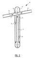
- FIG. 1 shows a heat exchanger 1 according to the invention.
- This heat exchanger 1 has a header 2 onto which a supply conduit 3 a discharge conduit 4 and a vertical pipe 5 are arranged.
- a heat exchanging fluid F is supplied by supply conduit 3 and flows into the header 2. Part of the fluid F directly flows to the discharge conduit 4 and part drops down into the vertical pipe 5.
- the fluid in the vertical pipe 5 is heated from the outside through the wall such that the fluid F reaches its boiling point and vapour bubbles G develop. These vapour bubbles G trust part of the fluid F upward and into the discharge conduit 4.
- FIG. 2 shows a second embodiment 10 of a heat exchanger according to the invention.
- This heat exchanger 10 has a header 11 onto which a supply conduit 12, a discharge conduit 13 and a vertical pipe 14 are attached.
- a connecting conduit 15 is arranged, which extends between the supply conduit 12 and the discharge conduit 13.
- the connecting conduit 15 has a bottom opening onto which a second vertical pipe 16 is arranged.
- the connecting conduit 15 has furthermore a top opening 17.
- vapour bubbles G When the fluid in the vertical pipe 14 is heated through the wall of the pipe 14, vapour bubbles G will be developed. This will trust part of fluid F upwardly, which flows through the top opening 17 into the discharge conduit 13. As a result of the development of vapour bubbles and the trusting of fluids F upwardly, a small under-pressure will be created, which promotes the flow of fluid F from the supply conduit 12 through the connecting conduit 15 into the bottom opening in the second vertical pipe 16. This vertical pipe 16 debouches at the bottom of the vertical pipe 14. As a result, a more controlled flow of the fluid F will occur and a better heat exchanging will be provided.
- FIG. 3 shows a third embodiment 20 of the heat exchanger according to the invention.
- This embodiment 20 has a header 21 to which a supply conduit 22 and a discharge conduit 23 is attached. Between the supply conduit 22 and discharge conduit 23 a connecting conduit 24 is arranged.
- This connecting conduit 24 has a bottom opening 25 to which a vertical pipe 26 is arranged.
- This vertical pipe 26 is coaxially arranged with the outer vertical pipe 27.
- the connecting conduit 24 has a top opening 28 which is provided with a deflector plate 29.
- This deflector plate 29 urges the fluid F into the vertical pipe 26, which debouches at the bottom into the vertical pipe 27 accordingly the embodiment of figure 2 .
- the deflector plate 29 also provides for a venturi effect at the top opening 28 such that heated fluid F is sucked into the top opening 28 and dragged along into the discharge conduit 23.
- FIG. 4 shows a fourth embodiment 30 of a heat exchanger according to the invention.
- This heat exchanger 30 has also a header 31 onto which a supply conduit 32, a discharge conduit 33 and a vertical pipe 34 are connected.
- the supply conduit 32 and discharge conduit 33 are interconnected by connecting conduit 35 which is provided with a top opening 36 a bottom opening 37 onto which a second vertical pipe 38 is arranged and side openings 39.
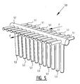
- FIG 5 part of a ceiling wall 50 of a boiler according to the invention is shown.
- the ceiling wall 50 consists out of a number of conduits 51 which are connected to each other in order to provide a closed wall. Through these conduits 51 a heat exchanging fluid, in particular water, flows.
- These conduits 51 are interrupted by a common header 52 from which vertical pipes 53 drop down.
- These vertical pipes 53 are embodied as disclosed above according to the invention.
- Fluid F flows into the conduits 51 and arrives at the common header 52.
- part of the fluid drops down into the vertical pipe 53, where it is heated by hot gasses present in the combustion chamber of the boiler. After reaching the boiling temperature of the fluid F vapour bubbles will develop and push part of the fluid back out of the vertical pipes 53 into the header 52 where it can proceed with the travel through the conduits 51.
- figure 5 shows an embodiment with a common header 52, it is also possible to provide for a curtain of vertical pipes wherein each vertical pipe connects to a pipe in the ceiling wall via a separate header.
Landscapes
- Engineering & Computer Science (AREA)
- Physics & Mathematics (AREA)
- Thermal Sciences (AREA)
- Mechanical Engineering (AREA)
- General Engineering & Computer Science (AREA)
- Chemical & Material Sciences (AREA)
- Combustion & Propulsion (AREA)
- Heat-Exchange Devices With Radiators And Conduit Assemblies (AREA)
Priority Applications (1)
| Application Number | Priority Date | Filing Date | Title |
|---|---|---|---|
| EP08075741A EP2159506A1 (de) | 2008-09-02 | 2008-09-02 | Wärmetauscher |
Applications Claiming Priority (1)
| Application Number | Priority Date | Filing Date | Title |
|---|---|---|---|
| EP08075741A EP2159506A1 (de) | 2008-09-02 | 2008-09-02 | Wärmetauscher |
Publications (1)
| Publication Number | Publication Date |
|---|---|
| EP2159506A1 true EP2159506A1 (de) | 2010-03-03 |
Family
ID=40290984
Family Applications (1)
| Application Number | Title | Priority Date | Filing Date |
|---|---|---|---|
| EP08075741A Withdrawn EP2159506A1 (de) | 2008-09-02 | 2008-09-02 | Wärmetauscher |
Country Status (1)
| Country | Link |
|---|---|
| EP (1) | EP2159506A1 (de) |
Cited By (1)
| Publication number | Priority date | Publication date | Assignee | Title |
|---|---|---|---|---|
| JP2019045024A (ja) * | 2017-08-30 | 2019-03-22 | 三菱日立パワーシステムズ株式会社 | ボイラ構造 |
Citations (2)
| Publication number | Priority date | Publication date | Assignee | Title |
|---|---|---|---|---|
| DE283772C (de) * | ||||
| US4443188A (en) * | 1981-05-20 | 1984-04-17 | Bbc Brown, Boveri & Company, Ltd. | Liquid cooling arrangement for industrial furnaces |
-
2008
- 2008-09-02 EP EP08075741A patent/EP2159506A1/de not_active Withdrawn
Patent Citations (2)
| Publication number | Priority date | Publication date | Assignee | Title |
|---|---|---|---|---|
| DE283772C (de) * | ||||
| US4443188A (en) * | 1981-05-20 | 1984-04-17 | Bbc Brown, Boveri & Company, Ltd. | Liquid cooling arrangement for industrial furnaces |
Cited By (1)
| Publication number | Priority date | Publication date | Assignee | Title |
|---|---|---|---|---|
| JP2019045024A (ja) * | 2017-08-30 | 2019-03-22 | 三菱日立パワーシステムズ株式会社 | ボイラ構造 |
Similar Documents
| Publication | Publication Date | Title |
|---|---|---|
| US10473407B2 (en) | Water heater having secondary heat exchanger | |
| KR101146020B1 (ko) | 콘덴싱 보일러의 2차 열교환기 | |
| KR20110077307A (ko) | 콘덴싱 보일러의 2차 열교환기 | |
| JP2012117736A (ja) | 燃焼器具 | |
| KR101287693B1 (ko) | 하이브리드 보일러 | |
| EP2159506A1 (de) | Wärmetauscher | |
| KR101757982B1 (ko) | 온도 저감식 스케일 방지 구조를 갖는 저탕식 열교환기 | |
| RU2011140812A (ru) | Проточный испаритель | |
| KR101642351B1 (ko) | 보일러 | |
| CN101476770A (zh) | 一种连续供水热水炉 | |
| FI120557B (fi) | Lämmönsiirrinyksikkö lämmön talteenottamiseksi kuumasta kaasuvirtauksesta | |
| NO801257L (no) | Oppvarmingsapparat for luft eller vann. | |
| JP3123180U (ja) | 給湯槽 | |
| KR20050057273A (ko) | 화로벽 구조 | |
| CN205425426U (zh) | 卧式单回程燃气热水锅炉 | |
| KR200414752Y1 (ko) | 화염 와류형 보일러 | |
| RU42882U1 (ru) | Секционный водотрубный, цельносварной водогрейный котел | |
| RU2181467C1 (ru) | Секционный водогрейный котел | |
| KR20140115740A (ko) | 보일러 | |
| RU2460946C1 (ru) | Водонагревательный терморегулируемый бак с коаксиальным энергоэффективным дымоходом (варианты) | |
| JP4716011B2 (ja) | 温水機器 | |
| RU102774U1 (ru) | Пароводяной теплообменник | |
| JP4874666B2 (ja) | 燃焼機器 | |
| US10260744B2 (en) | Chemical recovery boiler | |
| CN120351521A (zh) | 燃煤发电机组用烟气余热利用设备 |
Legal Events
| Date | Code | Title | Description |
|---|---|---|---|
| PUAI | Public reference made under article 153(3) epc to a published international application that has entered the european phase |
Free format text: ORIGINAL CODE: 0009012 |
|
| AK | Designated contracting states |
Kind code of ref document: A1 Designated state(s): AT BE BG CH CY CZ DE DK EE ES FI FR GB GR HR HU IE IS IT LI LT LU LV MC MT NL NO PL PT RO SE SI SK TR |
|
| AX | Request for extension of the european patent |
Extension state: AL BA MK RS |
|
| AKY | No designation fees paid | ||
| REG | Reference to a national code |
Ref country code: DE Ref legal event code: 8566 |
|
| STAA | Information on the status of an ep patent application or granted ep patent |
Free format text: STATUS: THE APPLICATION IS DEEMED TO BE WITHDRAWN |
|
| 18D | Application deemed to be withdrawn |
Effective date: 20100904 |