EP2159549B1 - Dispositif de mesure de la position relative entre une mesure matérialisée et une tête de lecture - Google Patents
Dispositif de mesure de la position relative entre une mesure matérialisée et une tête de lecture Download PDFInfo
- Publication number
- EP2159549B1 EP2159549B1 EP08015103.8A EP08015103A EP2159549B1 EP 2159549 B1 EP2159549 B1 EP 2159549B1 EP 08015103 A EP08015103 A EP 08015103A EP 2159549 B1 EP2159549 B1 EP 2159549B1
- Authority
- EP
- European Patent Office
- Prior art keywords
- indexing
- measuring
- incremental
- read head
- permanent magnets
- Prior art date
- Legal status (The legal status is an assumption and is not a legal conclusion. Google has not performed a legal analysis and makes no representation as to the accuracy of the status listed.)
- Not-in-force
Links
- 238000005070 sampling Methods 0.000 claims description 2
- 238000013461 design Methods 0.000 description 3
- 238000011156 evaluation Methods 0.000 description 3
- 238000005259 measurement Methods 0.000 description 3
- 238000000034 method Methods 0.000 description 2
- 238000012549 training Methods 0.000 description 2
- 230000001939 inductive effect Effects 0.000 description 1
- 230000003287 optical effect Effects 0.000 description 1
- 230000000737 periodic effect Effects 0.000 description 1
- 210000002023 somite Anatomy 0.000 description 1
- 230000001960 triggered effect Effects 0.000 description 1
Images

Classifications
-
- G—PHYSICS
- G01—MEASURING; TESTING
- G01D—MEASURING NOT SPECIALLY ADAPTED FOR A SPECIFIC VARIABLE; ARRANGEMENTS FOR MEASURING TWO OR MORE VARIABLES NOT COVERED IN A SINGLE OTHER SUBCLASS; TARIFF METERING APPARATUS; MEASURING OR TESTING NOT OTHERWISE PROVIDED FOR
- G01D5/00—Mechanical means for transferring the output of a sensing member; Means for converting the output of a sensing member to another variable where the form or nature of the sensing member does not constrain the means for converting; Transducers not specially adapted for a specific variable
- G01D5/12—Mechanical means for transferring the output of a sensing member; Means for converting the output of a sensing member to another variable where the form or nature of the sensing member does not constrain the means for converting; Transducers not specially adapted for a specific variable using electric or magnetic means
- G01D5/244—Mechanical means for transferring the output of a sensing member; Means for converting the output of a sensing member to another variable where the form or nature of the sensing member does not constrain the means for converting; Transducers not specially adapted for a specific variable using electric or magnetic means influencing characteristics of pulses or pulse trains; generating pulses or pulse trains
- G01D5/245—Mechanical means for transferring the output of a sensing member; Means for converting the output of a sensing member to another variable where the form or nature of the sensing member does not constrain the means for converting; Transducers not specially adapted for a specific variable using electric or magnetic means influencing characteristics of pulses or pulse trains; generating pulses or pulse trains using a variable number of pulses in a train
- G01D5/2454—Encoders incorporating incremental and absolute signals
- G01D5/2455—Encoders incorporating incremental and absolute signals with incremental and absolute tracks on the same encoder
- G01D5/2457—Incremental encoders having reference marks
Definitions
- the invention relates to a device for measuring the relative position between a material measure and a read head.
- the material measure In order to measure the relative position of two linearly or rotationally mutually movable objects, it is known to associate with the one object a material measure which is scanned by a reading head assigned to the second object.
- the material measure For incremental systems, the material measure has an incremental graduation with equidistant marks, which are counted during the relative movement by means of the read head.
- the material measure In absolute systems, the material measure has an encoding which is read by the read head and indicates the respective position. For the incremental systems, a starting position for the count must always be specified, while in the case of the absolute systems, the position can be read directly by the coding when switching on.
- Incremental systems have the advantage that the material measure can be produced relatively easily even with high resolution.
- the resolution can be further improved by interpolating the sinusoidal signals which are usually produced during the scanning of the periodic division, whereby the resolution can be improved by up to 2 or 3 orders of magnitude.
- the measuring range is limited especially for linear measuring systems.
- the larger the measuring distance the more code tracks are needed to encode the absolute position with a sufficient resolution.
- This disadvantage is according to DE 10 2006 017 865 A1 encountered in that the material measure in the measuring direction into individual segments, that is subdivided into successive sections. Each segment is absolutely coded in a consistent manner. Since the absolute coding is limited to the length of the segments, a sufficient resolution can be obtained with just a few bits.
- the individual segments are each associated with permanent magnetic markings which are detected during the relative movement by the reading head and generate counting pulses which are counted incrementally depending on the direction of movement upwards or downwards. The respective counter reading is thus assigned to the segment of the respective current position.
- the counter reading is stored permanently, so that the absolute position is available even after a service interruption.
- batteries can be used.
- the read head is formed with a Wieganddraht device, on the one hand detects the permanent magnetic markers and on the other hand feeds the counter circuit by means of their pulse energy.
- a measuring device in which permanent magnets are arranged in an incremental pitch.
- the pitch is sensed by a read head with magnetic field sensors that measure the magnetic field strength between each successive permanent magnet to interpolate the pitch between the successive permanent magnets.
- From the US 6,002,250 A For example, it is known to inductively scan an incremental graduation, the sampled signals being evaluated for the interpolation of the graduation steps.
- the invention has for its object to provide a device for measuring the relative position available, which allows a high resolution in a cost effective manner and has virtually no restrictions with respect to the measuring section.
- the device according to the invention for measuring the relative position between a material measure and a read head has a material measure and a read head.
- the material measure is permanently assigned to an object, while the read head is permanently assigned to a second object which is relatively movable with respect to the first object.
- the relative movement may be a linear movement or a rotational movement. Accordingly, the material measure is linear or circular.
- the material measure has an incremental pitch, which may be formed in a conventional manner.
- the read head has a scan corresponding to the incremental graduation, which scan can also be formed in a manner known per se.
- the incremental graduation scan generally generates approximately sinusoidal signals, which involve a further interpolation of the incremental graduation steps in a downstream one enable electronic evaluation.
- the incremental pitch can be an optically scanned pitch that allows for very high resolution but is mechanically sensitive.
- the incremental pitch may further be a capacitive sample, which, while not capable of very high resolution, is extremely robust.
- the incremental pitch can be scanned inductively, for example according to the eddy current principle, which also allows a robust design and in particular a version with a high degree of protection (IP 69 K). All these divisions and their sampling are known in the art. According to the invention, only a magnetic design of the incremental parts is excluded.
- the measuring standard on permanent magnets which are arranged equidistantly in the measuring direction, ie in the direction of relative movement.
- the permanent magnets define gapless adjoining segments or subsections of the incremental graduation.
- the magnetic field generated by the respective permanent magnets in the measuring direction is detected by at least one magnetic sensor of the reading head. This magnetic sensor detects in a conventional manner, as for example in the DE 32 44 891 C2 is described, the respective size of the magnetic field in the current position of the read head. This size of the magnetic field is clearly associated with a division step of the incremental division within the segment.
- the read head is still equipped with a Wieganddraht device (impulse wire device).
- This Wieganddraht device generates when driving over the permanent magnets each segment count pulses counted in an associated counter depending on the direction of movement up or down become.
- the counter reading thus indicates the segment of the material measure in which the read head is currently located, starting from an original zero position.
- the counter stores the respective counter reading captive so that the respective counter reading and thus the absolute position of the segment in which the read head is currently located are preserved even in the event of an interruption in operation.
- the counter circuit may be supplied with the memory by a battery.
- the resolution of the measuring device is determined by the incremental graduation and its interpolation, so that the high resolution of known devices can be achieved, regardless of the length of the measuring path.
- the current position can be determined absolutely, on the one hand, by counting the segments and by memorably saving the counter reading and, on the other hand, by assigning the position of the read head within a segment via the magnetic sensors to absolutely one incremental graduation increment.
- the counting means counts the generated by the Wieganddraht device segment counting pulses of the read head in the forward or reverse direction over run permanent magnets and captively stores the count.
- this counter reading therefore indicates absolutely in which segment the read head is located.
- the length of the measuring section ie the number of segments, is subject to virtually no restriction.
- the scanning of the magnetic field of the permanent magnets by the magnetic sensors of the reading head gives an absolute position indication within which division step of the incremental graduation within the respective segment the read head is located. This position information is absolutely available when switching on the device. Within the division step, the position is again measured by interpolating the scanning signals with a higher resolution.
- the device according to the invention thus combines the advantages of the achievable with relatively simple means high resolution incremental graduation with the advantages of an absolute position determination, without the measuring range is subject to a restriction due to the cost or design.
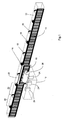
- the invention is shown in an embodiment as a linear measuring device.
- An analog training as rotary measuring system results for the expert in a natural way.
- the device consists of a material measure 10 and a read head 12.
- the material measure 10 and the read head 12 are each represented schematically by a housing.
- the material measure 10 is shown in the drawing in a section of limited linear extent. As explained above, the measuring scale 10 can have a virtually unlimited length.
- the material measure 10 is firmly connected to an object, while the read head 12 is fixedly connected to a second object.
- the two objects are mutually movable, in particular in the longitudinal direction of the measuring scale 10 against each other movable, as in FIG. 2 indicated by a double arrow.
- the measuring scale 10 has an incremental graduation 14, which extends over the entire length of the material measure 10 in the measuring direction, i. the direction of movement extends.
- the incremental graduation 14 is scanned by a scan 16 of the read head 12.
- the incremental graduation 14 and the scan 16 may be formed in a conventional manner optical, inductive or capacitive. Excluded is only a magnetic training of the incremental pitch 14.
- the scan 16 generated in the movement over the incremental pitch 14 in a conventional manner scanning signals that have a sinusoidal shape substantially.
- the sinusoidal form of the scanning signals makes it possible, in a manner known per se, to interpolate the pitch of the incremental graduation 14, so that the resolution can again be improved by more than a factor of 1000 (up to 14 bits) compared to the resolution of the pitch 14 on the order of magnitude.
- the measuring scale 10 permanent magnets 18 which are arranged in the measuring direction, ie in the longitudinal direction of the measuring scale 10 at equidistant intervals.
- the permanent magnets 18 are arranged so that they each facing the read head 12 alternately with its north pole or south pole. In the drawing, the permanent magnets 18 are arranged on the side remote from the reading head 12 of the measuring scale 10. Other arrangements are also possible.
- the incremental graduation 14 is subdivided into segments 20, ie into subsections. Each segment 20 extends from a permanent magnet 18 to the next in the measuring direction permanent magnet 18.
- the segments 20 close gapless and comprise several graduation steps of the incremental pitch 14.
- the permanent magnets 18 generate a magnetic field 22, whose field lines each of a permanent magnet 18th to the following Permanent magnets 18 extend, as in FIG. 2 indicated by arrows.
- the field lines of the magnetic fields 22 thus extend with changing field strength over the length of the segments 20.
- At least one magnetic sensor 24 is arranged, in the illustrated embodiment, three magnetic sensors 24 are arranged spaced apart in the measuring direction.
- the magnetic field 22 of the permanent magnets 18 passes through the non-magnetic incremental graduation 14 and the read head 12.
- the magnetic sensors 24 each detect the magnetic field strength of these magnetic fields 22. Since the magnetic field strength changes over the length of the segment, by means of the magnetic sensors 24, the position of the Read head 12 are determined within the length of the respective segment 20.
- the magnetic sensors 24 may be, for example, magnetoresistive sensors, such as in DE 32 44 891 C2 is described.
- the length of the segments 20, the number of pitch steps of the incremental pitch 14 within the segments 20 and the magnetic sensors 24 are dimensioned such that by measuring the magnetic field strength by means of the magnetic sensors 24, the current position of the read head 12 a certain division step of the incremental pitch 14th can be clearly assigned.
- the spacing of the permanent magnets 18 corresponds at least to the length of the reading head 12.
- a Wieganddraht device is arranged in the read head 12, which consists of a Wiegand wire 26 (pulse wire), which is aligned in the measuring direction, ie in the direction of relative movement and is wound with a coil 28.
- a Wiegand wire 26 pulse wire
- an electric pulse is triggered in the Wieganddraht 26 whose polarity depends on the direction of movement of the read head 12 relative to the material measure 10.
- These voltage pulses are supplied as a segment count pulses of an electronic counter circuit, not shown, which counts these segment counts up or down depending on the direction of movement.
- the respective counter reading is stored in a memory of the electronic evaluation captive. For feeding the counter circuit and for captive storage, the speed-independent energy of the pulses of Wieganddrahtes 26 is stored, so that the read head 12 with the electronic evaluation energy self-sufficient and independent of external energy sources.
- the measuring device is once entered a zero position of the reading head 12 relative to the material measure 10.
- the segments 20 run over by the reading head are counted upwards and downwards by the weighing-wire device 26, 28, depending on the direction of movement.
- the current counter reading is stored permanently. The stored counter reading is therefore at any time, even when restarting after an interruption in operation and possibly a movement of the measuring device during this time, absolutely, before which segment 20, the read head 12 is located.
- the measurement of the magnetic field 22 by the magnetic sensors 24 further indicates absolutely before which pitch step of the incremental graduation 14 within the displayed segment 20 the read head 12 is located. Within this division step, the sample 16 can now again interpolate the exact position with high resolution.
Landscapes
- Physics & Mathematics (AREA)
- General Physics & Mathematics (AREA)
- Transmission And Conversion Of Sensor Element Output (AREA)
Claims (9)
- Dispositif pour mesurer la position relative entre l'échelle de mesure (10) et une tête de lecture (12) comprenant- une échelle de mesure (10) ayant un encliquetage (14),- une tête de lecture (12) qui balaye l'indexation (14) d'une manière non-magnétique à haute résolution, l'échelle de mesure (10) comprend dans la direction de mesure des aimants de façon équidistante disposés permanents (18) qui définissent des segments adjacents (20) de la indexation (14), et dans lequel un moyen de fil de Wiegand (26, 28) de la tête de lecture (12) génère des segments d'impulsions de comptage lors du passage sur les aimants permanents (18), les chiffres de segment sont imperdable comptés dans un mémoire,caractérisé
en ce que l'encliquetage (14) est un indexage incrémental, en ce que les segments (20) comprennent une pluralité d'étapes d'indexation de l'indexation incrémentale (14),
en ce que le champ magnétique (22) généré par chaque aimant permanent successif (18) est détecté par au moins un capteur magnétique (24) de la tête de lecture (12),
en ce que la position de la tête de lecture (12) est associée à une étape respective d'indexation de l'indexation incrémentale (14) dans le segment (20) fixé par ces aimants permanents (18) par la grandeur du champ magnétique détecté (22) et
en ce que les signaux de l'échantillonnage (16) de l'indexage incrémental (14) sont évalués pour l'interpolation des étapes d'indexation. - Dispositif selon la revendication 1, dans lequel ledit indexage incrémental (14) est de manière capacitive ou inductive ou optique numérisé.
- Dispositif selon la revendication 1 ou 2, dans lequel les capteurs magnétiques (24) sont des capteurs magnétorésistifs.
- Dispositif selon la revendication 1, dans lequel la mémoire compte les pulses de comptage de segment vers le haut ou vers le bas en fonction de la direction du mouvement relatif.
- Dispositif selon la revendication 1, dans lequel le circuit de comptage et la mémoire sont indépendants des sources d'énergie externes.
- Dispositif selon la revendication 5, dans lequel le circuit de comptage et la mémoire sont alimentés par une batterie.
- Dispositif selon la revendication 5, dans lequel le circuit de comptage et la mémoire sont alimentés par l'énergie des impulsions de comptage du segment.
- Dispositif selon l'une quelconque des revendications précédentes, dans lequel les aimants permanents (18) avec polarité alternée suivent l'un après l'autre.
- Dispositif selon l'une quelconque des revendications précédentes, dans lequel la distance entre les aimants permanents (18) dans la direction de mesure est au moins égale à la longueur de la tête de lecture (12) dans la direction de mesure.
Priority Applications (2)
| Application Number | Priority Date | Filing Date | Title |
|---|---|---|---|
| EP08015103.8A EP2159549B1 (fr) | 2008-08-27 | 2008-08-27 | Dispositif de mesure de la position relative entre une mesure matérialisée et une tête de lecture |
| US12/461,497 US7908762B2 (en) | 2008-08-27 | 2009-08-13 | Device for measuring the relative position of a material measure and a reading head |
Applications Claiming Priority (1)
| Application Number | Priority Date | Filing Date | Title |
|---|---|---|---|
| EP08015103.8A EP2159549B1 (fr) | 2008-08-27 | 2008-08-27 | Dispositif de mesure de la position relative entre une mesure matérialisée et une tête de lecture |
Publications (2)
| Publication Number | Publication Date |
|---|---|
| EP2159549A1 EP2159549A1 (fr) | 2010-03-03 |
| EP2159549B1 true EP2159549B1 (fr) | 2015-10-07 |
Family
ID=40139138
Family Applications (1)
| Application Number | Title | Priority Date | Filing Date |
|---|---|---|---|
| EP08015103.8A Not-in-force EP2159549B1 (fr) | 2008-08-27 | 2008-08-27 | Dispositif de mesure de la position relative entre une mesure matérialisée et une tête de lecture |
Country Status (2)
| Country | Link |
|---|---|
| US (1) | US7908762B2 (fr) |
| EP (1) | EP2159549B1 (fr) |
Families Citing this family (10)
| Publication number | Priority date | Publication date | Assignee | Title |
|---|---|---|---|---|
| US9803998B1 (en) | 2013-12-31 | 2017-10-31 | Joral Llc | Absolute position sensor with fine resolution |
| US10969214B2 (en) | 2013-12-31 | 2021-04-06 | Joral Llc | Position sensor with Wiegand wire, position magnet(s) and reset magnet |
| PT3325914T (pt) * | 2015-07-23 | 2020-04-07 | Actimesure | Instrumento automático para suturas de cordão de bolsa para uso cirurgico. |
| US12405134B2 (en) * | 2018-06-28 | 2025-09-02 | Siemens Aktiengesellschaft | Electronic seal label apparatus, electric motor assembly and electronic seal label verification method |
| US11105608B2 (en) * | 2019-10-24 | 2021-08-31 | Pixart Imaging Inc. | Optical positioning system and operating method thereof |
| US11181406B2 (en) | 2019-12-03 | 2021-11-23 | Woodward, Inc. | Ultrasonic mass fuel flow meter |
| US12140669B2 (en) * | 2020-08-07 | 2024-11-12 | Woodward, Inc. | Ratio metric position sensor and control system |
| US11885655B2 (en) | 2020-08-07 | 2024-01-30 | Woodward, Inc. | Ultrasonic flow meter having flow conditioning arrangements for flow controlling in a linear fluid conduit |
| US11835374B2 (en) | 2021-03-17 | 2023-12-05 | Woodward, Inc. | Ultrasonic mass fuel flow meter |
| US12613119B2 (en) | 2021-08-27 | 2026-04-28 | Woodward, Inc. | Ultrasonic mass fuel flow meter |
Citations (2)
| Publication number | Priority date | Publication date | Assignee | Title |
|---|---|---|---|---|
| US6002250A (en) * | 1996-05-13 | 1999-12-14 | Mitutoyo Corporation | Electronic linear scale using a self-contained, low-power inductive position transducer |
| WO2003012972A1 (fr) * | 2001-07-20 | 2003-02-13 | Siemens Aktiengesellschaft | Dispositif de mesure et procede de regulation de moteurs electriques |
Family Cites Families (11)
| Publication number | Priority date | Publication date | Assignee | Title |
|---|---|---|---|---|
| JPS5866001A (ja) * | 1981-10-15 | 1983-04-20 | Sony Magnescale Inc | 磁気スケ−ル装置 |
| AT404300B (de) * | 1992-02-20 | 1998-10-27 | Rsf Elektronik Gmbh | Drehgeber |
| EP1321745A4 (fr) * | 2000-09-25 | 2005-09-07 | Tokai Rika Co Ltd | Detecteur d'angle tournant |
| US6922907B2 (en) * | 2001-04-05 | 2005-08-02 | Anton Rodi | Measuring system for recording absolute angular or position values |
| US6912797B2 (en) * | 2001-04-05 | 2005-07-05 | Anton Rodi | Measuring system for recording absolute angular or position values |
| JP4518833B2 (ja) * | 2004-02-03 | 2010-08-04 | 矢崎総業株式会社 | 回転角センサ |
| GB0415141D0 (en) * | 2004-07-06 | 2004-08-11 | Renishaw Plc | Scale reading apparatus |
| DE202004014849U1 (de) * | 2004-09-23 | 2005-02-03 | Trw Automotive Safety Systems Gmbh | Vorrichtung zur Bestimmung eines absoluten Drehwinkels |
| DE102005047009A1 (de) * | 2005-09-30 | 2007-04-05 | Bosch Rexroth Mechatronics Gmbh | Absolutes Positionsmesssystem |
| DE102006017865B4 (de) * | 2006-04-13 | 2012-04-12 | Sick Stegmann Gmbh | Vorrichtung zur Messung der absoluten Position eines Messobjekts |
| US7971487B2 (en) * | 2008-05-02 | 2011-07-05 | Carlen Controls, Inc. | Linear position transducer with wireless read head |
-
2008
- 2008-08-27 EP EP08015103.8A patent/EP2159549B1/fr not_active Not-in-force
-
2009
- 2009-08-13 US US12/461,497 patent/US7908762B2/en not_active Expired - Fee Related
Patent Citations (2)
| Publication number | Priority date | Publication date | Assignee | Title |
|---|---|---|---|---|
| US6002250A (en) * | 1996-05-13 | 1999-12-14 | Mitutoyo Corporation | Electronic linear scale using a self-contained, low-power inductive position transducer |
| WO2003012972A1 (fr) * | 2001-07-20 | 2003-02-13 | Siemens Aktiengesellschaft | Dispositif de mesure et procede de regulation de moteurs electriques |
Also Published As
| Publication number | Publication date |
|---|---|
| EP2159549A1 (fr) | 2010-03-03 |
| US7908762B2 (en) | 2011-03-22 |
| US20100050455A1 (en) | 2010-03-04 |
Similar Documents
| Publication | Publication Date | Title |
|---|---|---|
| EP2159549B1 (fr) | Dispositif de mesure de la position relative entre une mesure matérialisée et une tête de lecture | |
| EP2221587B1 (fr) | Indicateur de position magnétique absolu | |
| EP2182330B1 (fr) | Système de mesure de position/trajectoire doté d'un corps de mesure codé | |
| EP2561319B1 (fr) | Dispositif de détection de position et procédé de fabrication d'un agencement de marquage pour un dispositif de détection de position | |
| EP2533018B1 (fr) | Système de mesure de trajectoire linéaire | |
| EP1662232A1 (fr) | Capteur de position linéaire | |
| EP3803278B1 (fr) | Codeur absolu | |
| DE20311861U1 (de) | Vorrichtung zur Positions- und/oder Längenbestimmung | |
| DE102011000486A1 (de) | Absolutes Positionsmesssystem | |
| EP3179216A1 (fr) | Système de mesure de longueur absolu et son procédé de fonctionnement | |
| EP1236968A2 (fr) | Dispositif de mesure magnétique de longueur | |
| DE102018118477A1 (de) | Absolutwertgeber | |
| DE102008010095A1 (de) | Maßverkörperung, Messeinrichtung und Messverfahren zur Absolutpositionsbestimmung | |
| DE202008013715U1 (de) | Vorrichtung zur Bestimmung der relativen Position zweier zueinander bewegbarer Objekte | |
| EP1321743B1 (fr) | Système pour mesurer une longueur absolue comprenant une barre de mesure qui se déplace relativement par rapport à des sondes de longueur mutuellement espacées | |
| DE102013222197A1 (de) | Positionsmesseinrichtung | |
| DE19632656A1 (de) | Verfahren und Vorrichtung zum berührungslosen Erfassen der Lage oder der Drehstellung eines Gegenstandes | |
| EP2116814B1 (fr) | Dispositif de mesure destiné à la détermination d'une position et/ou d'une vitesse | |
| DE102018203409A1 (de) | Linearbewegungsvorrichtung und Verfahren | |
| EP3764063B1 (fr) | Procédé de détermination de la position absolue d'une glissière d'un entrainement direct linéaire électrique et entrainement direct linéaire électrique | |
| EP2869035A1 (fr) | Système de mesure de position et procédé de régulation pour moteurs linéaires concaténés | |
| DE3926328A1 (de) | Vorrichtung zum messen von laengen, winkeln und dergleichen | |
| DE102006017865A1 (de) | Vorrichtung zur Messung der absoluten Position eines Messobjekts | |
| DE102012213717A1 (de) | Inkrementalwegsensor | |
| DE10209058B4 (de) | Verfahren und Bitmuster zur Bestimmung einer kinematischen Messgröße |
Legal Events
| Date | Code | Title | Description |
|---|---|---|---|
| PUAI | Public reference made under article 153(3) epc to a published international application that has entered the european phase |
Free format text: ORIGINAL CODE: 0009012 |
|
| 17P | Request for examination filed |
Effective date: 20090227 |
|
| AK | Designated contracting states |
Kind code of ref document: A1 Designated state(s): AT BE BG CH CY CZ DE DK EE ES FI FR GB GR HR HU IE IS IT LI LT LU LV MC MT NL NO PL PT RO SE SI SK TR |
|
| AX | Request for extension of the european patent |
Extension state: AL BA MK RS |
|
| AKX | Designation fees paid |
Designated state(s): AT BE BG CH CY CZ DE DK EE ES FI FR GB GR HR HU IE IS IT LI LT LU LV MC MT NL NO PL PT RO SE SI SK TR |
|
| 17Q | First examination report despatched |
Effective date: 20121025 |
|
| GRAP | Despatch of communication of intention to grant a patent |
Free format text: ORIGINAL CODE: EPIDOSNIGR1 |
|
| INTG | Intention to grant announced |
Effective date: 20150520 |
|
| GRAS | Grant fee paid |
Free format text: ORIGINAL CODE: EPIDOSNIGR3 |
|
| GRAA | (expected) grant |
Free format text: ORIGINAL CODE: 0009210 |
|
| AK | Designated contracting states |
Kind code of ref document: B1 Designated state(s): AT BE BG CH CY CZ DE DK EE ES FI FR GB GR HR HU IE IS IT LI LT LU LV MC MT NL NO PL PT RO SE SI SK TR |
|
| REG | Reference to a national code |
Ref country code: GB Ref legal event code: FG4D Free format text: NOT ENGLISH |
|
| REG | Reference to a national code |
Ref country code: AT Ref legal event code: REF Ref document number: 754019 Country of ref document: AT Kind code of ref document: T Effective date: 20151015 Ref country code: CH Ref legal event code: EP |
|
| REG | Reference to a national code |
Ref country code: IE Ref legal event code: FG4D Free format text: LANGUAGE OF EP DOCUMENT: GERMAN |
|
| REG | Reference to a national code |
Ref country code: DE Ref legal event code: R096 Ref document number: 502008013451 Country of ref document: DE |
|
| REG | Reference to a national code |
Ref country code: NL Ref legal event code: MP Effective date: 20151007 |
|
| REG | Reference to a national code |
Ref country code: LT Ref legal event code: MG4D |
|
| PG25 | Lapsed in a contracting state [announced via postgrant information from national office to epo] |
Ref country code: IS Free format text: LAPSE BECAUSE OF FAILURE TO SUBMIT A TRANSLATION OF THE DESCRIPTION OR TO PAY THE FEE WITHIN THE PRESCRIBED TIME-LIMIT Effective date: 20160207 Ref country code: IT Free format text: LAPSE BECAUSE OF FAILURE TO SUBMIT A TRANSLATION OF THE DESCRIPTION OR TO PAY THE FEE WITHIN THE PRESCRIBED TIME-LIMIT Effective date: 20151007 Ref country code: NO Free format text: LAPSE BECAUSE OF FAILURE TO SUBMIT A TRANSLATION OF THE DESCRIPTION OR TO PAY THE FEE WITHIN THE PRESCRIBED TIME-LIMIT Effective date: 20160107 Ref country code: HR Free format text: LAPSE BECAUSE OF FAILURE TO SUBMIT A TRANSLATION OF THE DESCRIPTION OR TO PAY THE FEE WITHIN THE PRESCRIBED TIME-LIMIT Effective date: 20151007 Ref country code: NL Free format text: LAPSE BECAUSE OF FAILURE TO SUBMIT A TRANSLATION OF THE DESCRIPTION OR TO PAY THE FEE WITHIN THE PRESCRIBED TIME-LIMIT Effective date: 20151007 Ref country code: LT Free format text: LAPSE BECAUSE OF FAILURE TO SUBMIT A TRANSLATION OF THE DESCRIPTION OR TO PAY THE FEE WITHIN THE PRESCRIBED TIME-LIMIT Effective date: 20151007 Ref country code: ES Free format text: LAPSE BECAUSE OF FAILURE TO SUBMIT A TRANSLATION OF THE DESCRIPTION OR TO PAY THE FEE WITHIN THE PRESCRIBED TIME-LIMIT Effective date: 20151007 |
|
| PG25 | Lapsed in a contracting state [announced via postgrant information from national office to epo] |
Ref country code: PT Free format text: LAPSE BECAUSE OF FAILURE TO SUBMIT A TRANSLATION OF THE DESCRIPTION OR TO PAY THE FEE WITHIN THE PRESCRIBED TIME-LIMIT Effective date: 20160208 Ref country code: PL Free format text: LAPSE BECAUSE OF FAILURE TO SUBMIT A TRANSLATION OF THE DESCRIPTION OR TO PAY THE FEE WITHIN THE PRESCRIBED TIME-LIMIT Effective date: 20151007 Ref country code: FI Free format text: LAPSE BECAUSE OF FAILURE TO SUBMIT A TRANSLATION OF THE DESCRIPTION OR TO PAY THE FEE WITHIN THE PRESCRIBED TIME-LIMIT Effective date: 20151007 Ref country code: GR Free format text: LAPSE BECAUSE OF FAILURE TO SUBMIT A TRANSLATION OF THE DESCRIPTION OR TO PAY THE FEE WITHIN THE PRESCRIBED TIME-LIMIT Effective date: 20160108 Ref country code: SE Free format text: LAPSE BECAUSE OF FAILURE TO SUBMIT A TRANSLATION OF THE DESCRIPTION OR TO PAY THE FEE WITHIN THE PRESCRIBED TIME-LIMIT Effective date: 20151007 Ref country code: LV Free format text: LAPSE BECAUSE OF FAILURE TO SUBMIT A TRANSLATION OF THE DESCRIPTION OR TO PAY THE FEE WITHIN THE PRESCRIBED TIME-LIMIT Effective date: 20151007 |
|
| REG | Reference to a national code |
Ref country code: DE Ref legal event code: R097 Ref document number: 502008013451 Country of ref document: DE |
|
| PG25 | Lapsed in a contracting state [announced via postgrant information from national office to epo] |
Ref country code: CZ Free format text: LAPSE BECAUSE OF FAILURE TO SUBMIT A TRANSLATION OF THE DESCRIPTION OR TO PAY THE FEE WITHIN THE PRESCRIBED TIME-LIMIT Effective date: 20151007 |
|
| PLBE | No opposition filed within time limit |
Free format text: ORIGINAL CODE: 0009261 |
|
| STAA | Information on the status of an ep patent application or granted ep patent |
Free format text: STATUS: NO OPPOSITION FILED WITHIN TIME LIMIT |
|
| PG25 | Lapsed in a contracting state [announced via postgrant information from national office to epo] |
Ref country code: RO Free format text: LAPSE BECAUSE OF FAILURE TO SUBMIT A TRANSLATION OF THE DESCRIPTION OR TO PAY THE FEE WITHIN THE PRESCRIBED TIME-LIMIT Effective date: 20151007 Ref country code: DK Free format text: LAPSE BECAUSE OF FAILURE TO SUBMIT A TRANSLATION OF THE DESCRIPTION OR TO PAY THE FEE WITHIN THE PRESCRIBED TIME-LIMIT Effective date: 20151007 Ref country code: SK Free format text: LAPSE BECAUSE OF FAILURE TO SUBMIT A TRANSLATION OF THE DESCRIPTION OR TO PAY THE FEE WITHIN THE PRESCRIBED TIME-LIMIT Effective date: 20151007 Ref country code: EE Free format text: LAPSE BECAUSE OF FAILURE TO SUBMIT A TRANSLATION OF THE DESCRIPTION OR TO PAY THE FEE WITHIN THE PRESCRIBED TIME-LIMIT Effective date: 20151007 |
|
| 26N | No opposition filed |
Effective date: 20160708 |
|
| PG25 | Lapsed in a contracting state [announced via postgrant information from national office to epo] |
Ref country code: SI Free format text: LAPSE BECAUSE OF FAILURE TO SUBMIT A TRANSLATION OF THE DESCRIPTION OR TO PAY THE FEE WITHIN THE PRESCRIBED TIME-LIMIT Effective date: 20151007 |
|
| PG25 | Lapsed in a contracting state [announced via postgrant information from national office to epo] |
Ref country code: BE Free format text: LAPSE BECAUSE OF NON-PAYMENT OF DUE FEES Effective date: 20160831 |
|
| PG25 | Lapsed in a contracting state [announced via postgrant information from national office to epo] |
Ref country code: MC Free format text: LAPSE BECAUSE OF FAILURE TO SUBMIT A TRANSLATION OF THE DESCRIPTION OR TO PAY THE FEE WITHIN THE PRESCRIBED TIME-LIMIT Effective date: 20151007 |
|
| REG | Reference to a national code |
Ref country code: CH Ref legal event code: PL |
|
| GBPC | Gb: european patent ceased through non-payment of renewal fee |
Effective date: 20160827 |
|
| PG25 | Lapsed in a contracting state [announced via postgrant information from national office to epo] |
Ref country code: CH Free format text: LAPSE BECAUSE OF NON-PAYMENT OF DUE FEES Effective date: 20160831 Ref country code: LI Free format text: LAPSE BECAUSE OF NON-PAYMENT OF DUE FEES Effective date: 20160831 |
|
| REG | Reference to a national code |
Ref country code: FR Ref legal event code: ST Effective date: 20170428 |
|
| REG | Reference to a national code |
Ref country code: IE Ref legal event code: MM4A |
|
| PG25 | Lapsed in a contracting state [announced via postgrant information from national office to epo] |
Ref country code: IE Free format text: LAPSE BECAUSE OF NON-PAYMENT OF DUE FEES Effective date: 20160827 Ref country code: GB Free format text: LAPSE BECAUSE OF NON-PAYMENT OF DUE FEES Effective date: 20160827 Ref country code: FR Free format text: LAPSE BECAUSE OF NON-PAYMENT OF DUE FEES Effective date: 20160831 |
|
| PG25 | Lapsed in a contracting state [announced via postgrant information from national office to epo] |
Ref country code: LU Free format text: LAPSE BECAUSE OF NON-PAYMENT OF DUE FEES Effective date: 20160827 |
|
| REG | Reference to a national code |
Ref country code: AT Ref legal event code: MM01 Ref document number: 754019 Country of ref document: AT Kind code of ref document: T Effective date: 20160827 |
|
| PG25 | Lapsed in a contracting state [announced via postgrant information from national office to epo] |
Ref country code: AT Free format text: LAPSE BECAUSE OF NON-PAYMENT OF DUE FEES Effective date: 20160827 |
|
| PG25 | Lapsed in a contracting state [announced via postgrant information from national office to epo] |
Ref country code: HU Free format text: LAPSE BECAUSE OF FAILURE TO SUBMIT A TRANSLATION OF THE DESCRIPTION OR TO PAY THE FEE WITHIN THE PRESCRIBED TIME-LIMIT; INVALID AB INITIO Effective date: 20080827 Ref country code: CY Free format text: LAPSE BECAUSE OF FAILURE TO SUBMIT A TRANSLATION OF THE DESCRIPTION OR TO PAY THE FEE WITHIN THE PRESCRIBED TIME-LIMIT Effective date: 20151007 |
|
| PG25 | Lapsed in a contracting state [announced via postgrant information from national office to epo] |
Ref country code: TR Free format text: LAPSE BECAUSE OF FAILURE TO SUBMIT A TRANSLATION OF THE DESCRIPTION OR TO PAY THE FEE WITHIN THE PRESCRIBED TIME-LIMIT Effective date: 20151007 Ref country code: MT Free format text: LAPSE BECAUSE OF FAILURE TO SUBMIT A TRANSLATION OF THE DESCRIPTION OR TO PAY THE FEE WITHIN THE PRESCRIBED TIME-LIMIT Effective date: 20151007 |
|
| PG25 | Lapsed in a contracting state [announced via postgrant information from national office to epo] |
Ref country code: BG Free format text: LAPSE BECAUSE OF FAILURE TO SUBMIT A TRANSLATION OF THE DESCRIPTION OR TO PAY THE FEE WITHIN THE PRESCRIBED TIME-LIMIT Effective date: 20151007 |
|
| REG | Reference to a national code |
Ref country code: DE Ref legal event code: R082 Ref document number: 502008013451 Country of ref document: DE Ref country code: DE Ref legal event code: R081 Ref document number: 502008013451 Country of ref document: DE Owner name: SICK AG, DE Free format text: FORMER OWNER: SICK STEGMANN GMBH, 78166 DONAUESCHINGEN, DE |
|
| PGFP | Annual fee paid to national office [announced via postgrant information from national office to epo] |
Ref country code: DE Payment date: 20220822 Year of fee payment: 15 |
|
| REG | Reference to a national code |
Ref country code: DE Ref legal event code: R119 Ref document number: 502008013451 Country of ref document: DE |
|
| PG25 | Lapsed in a contracting state [announced via postgrant information from national office to epo] |
Ref country code: DE Free format text: LAPSE BECAUSE OF NON-PAYMENT OF DUE FEES Effective date: 20240301 |