EP2159596A2 - Radarvorrichtung - Google Patents
Radarvorrichtung Download PDFInfo
- Publication number
- EP2159596A2 EP2159596A2 EP09251323A EP09251323A EP2159596A2 EP 2159596 A2 EP2159596 A2 EP 2159596A2 EP 09251323 A EP09251323 A EP 09251323A EP 09251323 A EP09251323 A EP 09251323A EP 2159596 A2 EP2159596 A2 EP 2159596A2
- Authority
- EP
- European Patent Office
- Prior art keywords
- transmission pulse
- transmission
- pulse group
- pulses
- group
- Prior art date
- Legal status (The legal status is an assumption and is not a legal conclusion. Google has not performed a legal analysis and makes no representation as to the accuracy of the status listed.)
- Withdrawn
Links
- 230000005540 biological transmission Effects 0.000 claims abstract description 302
- 238000002592 echocardiography Methods 0.000 claims description 21
- 238000001228 spectrum Methods 0.000 claims description 14
- 238000009826 distribution Methods 0.000 claims description 13
- 238000001514 detection method Methods 0.000 claims description 12
- 230000001427 coherent effect Effects 0.000 claims description 4
- 230000001360 synchronised effect Effects 0.000 claims description 4
- 238000000034 method Methods 0.000 description 27
- 101100438752 Arabidopsis thaliana CPI1 gene Proteins 0.000 description 19
- 229920003211 cis-1,4-polyisoprene Polymers 0.000 description 18
- 238000001914 filtration Methods 0.000 description 18
- 101150002418 cpi-2 gene Proteins 0.000 description 17
- 238000001208 nuclear magnetic resonance pulse sequence Methods 0.000 description 9
- 238000000926 separation method Methods 0.000 description 7
- 238000006243 chemical reaction Methods 0.000 description 4
- 238000010586 diagram Methods 0.000 description 4
- 230000000694 effects Effects 0.000 description 4
- 230000002411 adverse Effects 0.000 description 3
- 101100353178 Saccharomyces cerevisiae (strain ATCC 204508 / S288c) PRI2 gene Proteins 0.000 description 2
- 101100353177 Schizosaccharomyces pombe (strain 972 / ATCC 24843) spp2 gene Proteins 0.000 description 2
- 230000003321 amplification Effects 0.000 description 2
- 238000007796 conventional method Methods 0.000 description 2
- 238000003199 nucleic acid amplification method Methods 0.000 description 2
- 101150047682 priL gene Proteins 0.000 description 2
- 201000004569 Blindness Diseases 0.000 description 1
- 238000005311 autocorrelation function Methods 0.000 description 1
- 238000004364 calculation method Methods 0.000 description 1
- 230000001678 irradiating effect Effects 0.000 description 1
- 238000005070 sampling Methods 0.000 description 1
- 230000001629 suppression Effects 0.000 description 1
- 230000002194 synthesizing effect Effects 0.000 description 1
Images


Classifications
-
- G—PHYSICS
- G01—MEASURING; TESTING
- G01S—RADIO DIRECTION-FINDING; RADIO NAVIGATION; DETERMINING DISTANCE OR VELOCITY BY USE OF RADIO WAVES; LOCATING OR PRESENCE-DETECTING BY USE OF THE REFLECTION OR RERADIATION OF RADIO WAVES; ANALOGOUS ARRANGEMENTS USING OTHER WAVES
- G01S13/00—Systems using the reflection or reradiation of radio waves, e.g. radar systems; Analogous systems using reflection or reradiation of waves whose nature or wavelength is irrelevant or unspecified
- G01S13/02—Systems using reflection of radio waves, e.g. primary radar systems; Analogous systems
- G01S13/50—Systems of measurement based on relative movement of target
- G01S13/52—Discriminating between fixed and moving objects or between objects moving at different speeds
- G01S13/522—Discriminating between fixed and moving objects or between objects moving at different speeds using transmissions of interrupted pulse modulated waves
- G01S13/524—Discriminating between fixed and moving objects or between objects moving at different speeds using transmissions of interrupted pulse modulated waves based upon the phase or frequency shift resulting from movement of objects, with reference to the transmitted signals, e.g. coherent MTi
- G01S13/526—Discriminating between fixed and moving objects or between objects moving at different speeds using transmissions of interrupted pulse modulated waves based upon the phase or frequency shift resulting from movement of objects, with reference to the transmitted signals, e.g. coherent MTi performing filtering on the whole spectrum without loss of range information, e.g. using delay line cancellers or comb filters
- G01S13/528—Discriminating between fixed and moving objects or between objects moving at different speeds using transmissions of interrupted pulse modulated waves based upon the phase or frequency shift resulting from movement of objects, with reference to the transmitted signals, e.g. coherent MTi performing filtering on the whole spectrum without loss of range information, e.g. using delay line cancellers or comb filters with elimination of blind speeds
-
- G—PHYSICS
- G01—MEASURING; TESTING
- G01S—RADIO DIRECTION-FINDING; RADIO NAVIGATION; DETERMINING DISTANCE OR VELOCITY BY USE OF RADIO WAVES; LOCATING OR PRESENCE-DETECTING BY USE OF THE REFLECTION OR RERADIATION OF RADIO WAVES; ANALOGOUS ARRANGEMENTS USING OTHER WAVES
- G01S7/00—Details of systems according to groups G01S13/00, G01S15/00, G01S17/00
- G01S7/02—Details of systems according to groups G01S13/00, G01S15/00, G01S17/00 of systems according to group G01S13/00
- G01S7/28—Details of pulse systems
- G01S7/285—Receivers
- G01S7/292—Extracting wanted echo-signals
- G01S7/2921—Extracting wanted echo-signals based on data belonging to one radar period
-
- G—PHYSICS
- G01—MEASURING; TESTING
- G01S—RADIO DIRECTION-FINDING; RADIO NAVIGATION; DETERMINING DISTANCE OR VELOCITY BY USE OF RADIO WAVES; LOCATING OR PRESENCE-DETECTING BY USE OF THE REFLECTION OR RERADIATION OF RADIO WAVES; ANALOGOUS ARRANGEMENTS USING OTHER WAVES
- G01S7/00—Details of systems according to groups G01S13/00, G01S15/00, G01S17/00
- G01S7/02—Details of systems according to groups G01S13/00, G01S15/00, G01S17/00 of systems according to group G01S13/00
- G01S7/28—Details of pulse systems
- G01S7/285—Receivers
- G01S7/288—Coherent receivers
- G01S7/2883—Coherent receivers using FFT processing
Definitions
- the present invention relates to a radar apparatus configured to detect a target, and more specifically, to a technique for improving Doppler frequency resolution.
- the present invention is applied based on the previous application filed with Japanese Patent Office under the application number P2008-215413, dated on August 25, 2008 .
- Moving target detection processing is known as standard processing of a radar apparatus. Since a radar received echo includes a target reflection signal and unnecessary reflection signals (which are called clutter) from grounds and the like, this moving target detection processing is for suppressing the clutter by discriminating the target reflection signal from the clutter on the basis of the moving speed of a target.
- a filtering process is performed on Doppler frequencies generated in relation to the moving speed of the target.
- Typical examples of this filtering process for the Doppler frequencies include MTI, FFT, and the like.
- a transmission frequency at the time of receiving a signal used for the Doppler filtering process must be coherent (i.e., phase-continuous at the same frequency) and transmission pulse intervals must be constant.
- a target search by the radar is performed by sequentially transmitting transmission pulses to a necessary range all around an antenna while rotating the antenna. Because the antenna is rotated, a time period for irradiating an intended target with the transmission radio waves is limited. The number of transmission pulses to be transmitted within this irradiation period is called a hit number.
- the above-described Doppler filtering process is performed on transmission pulses within a time period called a CPI (coherent processing interval) having this hit number as an upper limit, or in other words, on the same number of received echoes.
- the transmission frequency needs to be constant and the transmission pulse intervals also need to be constant.
- the transmission pulse intervals also need to be constant.
- Patent Literature 1 discloses a conventional technique concerning the above-described measure.
- a radar signal processing apparatus disclosed in this Patent Literature 1 includes: a MTI map generator configured to set up an MTI map in a fixed clutter region; an automatic clutter map generator configured to set up an automatic clutter map in a moving clutter region by use of an inputted video signal; a synchronizer configured to output trigger pulses for defining a staggering cycle, the trigger pulses having sampling intervals determined at least based on a Doppler characteristic of a target and on a hit number; a filtering coefficient controller configured to receive the MTI map, the automatic clutter map, and the trigger pulses and to output a predetermined different filtering coefficient in response to each of the trigger pulses; multiple filters set to have filtering characteristics based on the predetermined filtering coefficient outputted from the filtering coefficient controller; multiple clutter suppressors configured to perform clutter suppression processing on outputs from the multiple filters; and a greatest value selector configured to select the greatest value among outputs from the multiple clutter suppressors.
- the greatest value selector receives an output signal from the predetermined filter which is different for each trigger pulse, selects the greatest output signal, and synthesizes a radar signal to be outputted.
- the radar signal processing apparatus reduces an influence of MTI blindness in the multiple CPIs having different transmission pulse intervals by appropriately changing coefficients for Doppler filter banks for the CPIs. In this way, it is possible to obtain a target signal at a high detection probability.
- Non Patent Literature 3 discloses a technique for the thinning-out of the transmission pulses to be described later, for example.
- Non Patent Literature 3 discloses that it is possible to form Doppler filter banks even when a certain number of pulses are thinned out of a transmission pulse train with constant intervals.
- use of thinned-out transmission pulse trains for tracking the respective targets enables tracking of multiple targets at the same time, and thereby reduces necessary time.
- a conventional radar apparatus at least requires a certain number of transmission pulses even in the case of carrying out the Doppler filtering process to suppress the clutter. Accordingly, it is difficult to set up multiple CPIs when the hit number is extremely limited.
- the Doppler frequency resolution is degraded because the number of pulses included in one CPI is small and a length of the CPI (duration) is short. Accordingly, this Doppler filtering process using these CPIs has a limited performance.
- An object of the present invention is to provide a radar apparatus which is capable of effectively setting up multiple CPIs even when a hit number is limited.
- the present invention provides a radar apparatus which includes a transmission pulse group generator configured to generate: a first transmission pulse group from a first transmission pulse train formed of N first transmission pulses (N>2, where N is an integer number) having constant first time intervals t1, by thinning a first transmission pulse out of the first transmission pulse train so that all time intervals ranging from t1 to (N-1) * t1 are held by pairs of first transmission pulses selected from the first transmission pulse group; and a second transmission pulse group from a second transmission pulse train formed of M second transmission pulses (M>2, where M is an integer number) having second time intervals t2 different from the first time intervals t1, by thinning a second transmission pulse out of the second transmission pulse train so that all time intervals ranging from t2 to (M-1) * t2 are held by pairs of second transmission pulses selected from the second transmission pulse group.
- the radar apparatus also includes a transmitter configured to transmit the first transmission pulse group and the second transmission pulse group in an identical direction in a way that the first and
- the transmission pulse group generator generates: a first transmission pulse group from a first transmission pulse train formed of N transmission pulses (N>2, where N is an integer number) having constant first time intervals t1, by thinning a transmission pulse out of the first transmission pulse train so that all the time intervals ranging from t1 to (N-1) * t1 are held by pairs of transmission pulses selected from the first transmission pulse group; and a second transmission pulse group from a second transmission pulse train formed of M transmission pulses (M>2, where M is an integer number) having second time intervals t2 different from the first time intervals t1, by thinning a transmission pulse out of the second transmission pulse train so that all the time intervals ranging from t2 to (M-1) * t2 are held by pairs of transmission pulses selected from the second transmission pulse group.
- the transmitter transmits the first transmission pulse group and the second transmission pulse group in an identical direction in a way that the first and second transmission pulse groups partially or entirely overlap each other in terms of time.
- some of the transmission pulses are thinned out from the two types of continuous first and second transmission pulse trains having different pulse intervals. Then, both of the transmission pulse trains are overlapped one another while maintaining predetermined intervals so as not to cause troubles in the transmission and reception of the pulse trains. Then, the two types of the transmission pulse trains originally having the different pulse intervals are combined and transmitted at the same time in the form of overlapped transmission pulse trains. Therefore, it is possible to provide a radar apparatus which is capable of effectively setting up multiple CPIs even when a hit number is limited.
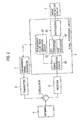
- Fig. 2 is a block diagram showing a configuration of a radar apparatus according to Example 1 of the present invention.
- This radar apparatus includes a transmission signal generator 1, a transmitter 2, a circulator 3, an antenna 4, a receiver 5, a signal processing circuit 6, and a target detection circuit 7.
- This radar apparatus is configured: to thin out some of transmission pulses from two types of continuous first and second transmission pulse trains that have different pulse intervals; to overlap the transmission pulse trains on one another in a way to maintain predetermined intervals between pulses of the two trains so as not to cause troubles in transmission and reception thereof; and then to combine and transmit the two types of the transmission pulse trains originally having the different pulse intervals at the same time in the form of the overlapped transmission pulse train.
- the transmitter 2 amplifies a transmission signal from the transmission signal generator 1.
- the transmission signal amplified by the transmitter 2 is sent to the antenna 4 through the circulator 3 and is then radiated from the antenna 4 to an open space as a transmission wave.
- the transmission wave radiated from the antenna 4 to the open space is reflected by a target and then inputted to the antenna 4.
- the antenna converts the reflected wave thus inputted into an electric signal and sends the electric signal to the receiver 5 through the circulator 3.
- the receiver 5 includes a high-frequency amplification circuit, a frequency conversion circuit, and an A/D conversion circuit (none of them are illustrated).
- the receiver 5 amplifies the signal sent from the antenna 4 through the circulator 3 by use of the high-frequency amplification circuit, converts the signal into an intermediate frequency signal (IF) by use of the frequency conversion circuit, converts the intermediate frequency signal into a digital signal by use of the A/D conversion circuit, and then sends the digital signal to the signal processing circuit 6 as a reception signal.
- IF intermediate frequency signal
- the signal processing circuit 6 subjects the reception signal sent from the receiver 5 to Doppler frequency processing (corresponding to conventional MTI processing or FFT processing, for example) and then outputs a result.
- the signal processing circuit 6 includes a transmission pulse train generation circuit 61, a signal separation circuit 62, a CPI1 processor 63, a CPI2 processor 64, and a synthesizer 65.
- the transmission pulse train generation circuit 61 corresponds to a transmission pulse group generator of the present invention.
- the transmission pulse train generation circuit 61 generates a first transmission pulse group PG1 and a second transmission pulse group PG2 and outputs the groups PG1 and PG2 to the transmission signal generator 1.
- the first transmission pulse group PG1 is generated from a first transmission pulse train CPI1 formed of N first transmission pulses (seven pulses, for example) having constant first time intervals t1, by thinning, for example, three first transmission pulses out of the first transmission pulse train CPI1 so that all the time intervals ranging from t1 to (N-1) * t1 are held by pairs of first transmission pulses selected from the first transmission pulse group PG1.
- the second transmission pulse group PG2 is generated from a second transmission pulse train CPI2 formed of M second transmission pulses (seven pulses, for example) having second time intervals t2 that are different from the first time intervals t1, by thinning, for example, three second transmission pulses out of the second transmission pulse train CPI2 so that all the time intervals ranging from t2 to (M-1) * t2 are held by pairs of second transmission pulses selected from the second transmission pulse group PG2.
- the transmission signal generator 1 corresponds to a transmitter of the present invention. Based on the first transmission pulse group PG1 and the second transmission pulse group PG2 from the transmission pulse train generation circuit 61, the transmission signal generator 1 generates a transmission signal formed of a transmission pulse sequence PG12 (shown in Fig. 3 ) so that the first transmission pulse group PG1 and the second transmission pulse group PG2 partially or entirely overlap one another in terms of time in transmission in the same direction.
- a transmission pulse sequence PG12 shown in Fig. 3
- the signal separation circuit 62 separates reception signal from the receiver 5, i.e., received echoes EC1 to EC8 as shown in Fig. 5 into the first transmission pulse group PG1 and the second transmission pulse group PG2 based on the first transmission pulse group PG1 and the second transmission pulse group PG2 from the transmission pulse train generation circuit 61.
- the CPI1 processor 63 corresponds to a calculator of the present invention, which is configured to calculate power spectrum distribution for each Doppler frequency based on the received echoes for the first transmission pulse group PG1 separated by the signal separation circuit 62.
- the CPI2 processor 64 also corresponds to the calculator of the present invention, which is configured to calculate power spectrum distribution for each Doppler frequency based on the received echoes for the second transmission pulse group PG2 separated by the signal separation circuit 62.
- the synthesizer 65 synthesizes the power spectrum distribution for the Doppler frequencies calculated by the CPI1 processor 63 and the power spectrum distribution for the Doppler frequencies calculated by the CPI2 processor 64, and then outputs the synthesized power spectrum distribution to the target detection circuit 7.
- the target detection circuit 7 detects a moving target by use of the power spectrum distribution calculated by the synthesizer 65 and outputs a target detection signal.
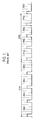
- Fig. 3 shows the first transmission pulse train, the second transmission pulse train, the first transmission pulse group PG1, the second transmission pulse group PG2, and the transmission pulse sequence PG12 that is to be actually transmitted.
- transmission pulses indicated with a solid line in CPI1 represent the first transmission pulse group PG1 and the combination of the transmission pulses indicated with the solid line and transmission pulses indicated with a dotted line represent the first transmission pulse train.
- transmission pulses indicated with a solid line in CPI2 represent the second transmission pulse group PG2 and the combination of the transmission pulses indicated with the solid line and transmission pulses indicated with a dotted line represent the second transmission pulse train.
- the present invention is not limited only to this configuration.
- each of the first transmission pulse group PG1 and the second transmission pulse group PG2 is formed by thinning some transmission pulses out of the first transmission pulse train and the second transmission pulse train.
- each of transmission pulse interval is set to a constant interval (PRI1 (pulse repeat interval) and PRI2) and an integral multiple of that interval. That is, the transmission pulse interval of the first transmission pulse group PG1 is different from the transmission pulse interval of the second transmission pulse group PG2.
- Fig. 4 is a view showing the transmission pulse group generated by thinning transmission pulses out of the transmission pulse train so as to contain all the time intervals by use of the radar apparatus of Example 1.
- the first transmission pulse group PG1 is formed by thinning thee transmission pulses out of the first transmission pulse train CPI1 so as to contain all the time intervals of t1, 2 * t1, 3 * t1, 4 * t1, 5 * t1, and 6 * t1 when selecting two transmission pulses from the first transmission pulse train CPI1.
- the method of thinning out the second transmission pulse group PG2 is similar to the method of thinning out the first transmission pulse group PG1.
- a transmission pulse group after thinned out includes at least one pulse pair having each of all the intervals ranging from a minimum interval (PRI1 or PRI2) to (N-1 (or M-1)) times of the minimum interval.
- the transmission pulse trains are thinned out, it is possible to appropriately overlap the first and second transmission pulse groups PG1 and PG2 with each other as shown in Fig. 3 so as not to cause troubles in transmitting and receiving both the pulse groups. Hence, it is apparent that the pulse trains having two types of transmission intervals can be transmitted at the same time.
- the transmission pulse sequence PG12 in Fig. 3 shows that it is possible to overlap the first transmission pulse group PG1 and the second transmission pulse group PG2 one another, each of which are equivalent to seven pulses, within a period required for transmitting eight pulses (two CPIs each having four pulses) in conventional practices.
- the two CPIs are formed at the same time so as to overlap each other throughout the original hit number. Accordingly, it is possible to improve the Doppler frequency resolution and to improve the S/N ratio as compared to the case of dividing the CPIs in terms of time.
- the signal separation circuit 62 separates the received echoes EC1 to EC8 that are sequentially inputted as shown in Fig. 5 , based on time information on the pulses of the first transmission pulse group PG1 and of the second transmission pulse group PG2 provided from the transmission pulse train generation circuit 61. Among these received echoes, the signal separation circuit 62 separates the received echoes EC1, EC2, EC5, and EC7 as the first transmission pulse group PG1 while separates the received echoes EC3, EC4, EC6, and EC8 as the second transmission pulse group PG2.
- the CPI1 processor 63 calculates power spectrum distribution for each of the Doppler frequencies based on the received echoes EC1, EC2, EC5, and EC7 for the first transmission pulse group PG1.
- the CPI2 processor 64 calculates power spectrum distribution for each of the Doppler frequencies based on the received echoes EC3, EC4, EC6, and EC8 for the second transmission pulse group PG2. Specifically, it is possible to obtain the results for the different multiple transmission time intervals by carrying out the Doppler filtering process for each of the received echoes with respect to the first transmission pulse group PG1 and the second transmission pulse group PG2. Hence, it is also possible to eliminate the blind speed.
- the present invention has a high compatibility with the conventionally used diversity method.
- the radar apparatus of Example 1 is configured: to thin some transmission pulses out of two types of continuous transmission pulse trains originally having the different pulse intervals,; to overlap the pulse trains on one another while maintaining the minimum intervals so as not to cause troubles in transmission and reception of the pulse trains: and then to combine and transmit the two types of the transmission pulse trains originally having the different pulse intervals at the same time in the form of the overlapped transmission pulse trains. Therefore, even when a hit number is limited, it is possible to set up multiple CPIs effectively and to eliminate the blind speed effectively at the same time.
- Fig. 6 is a block diagram showing a configuration of a radar apparatus according to Example 2 of the present invention.
- Fig. 7 is a view showing an example of transmission pulse trains of the radar apparatus according to Example 2 of the present invention.
- Fig. 8 is a view showing received echoes in response to transmission of the exemplified transmission pulse trains of the radar apparatus according to Example 2 of the present invention.
- the radar apparatus of Example 2 is configured to synchronize transmission pulse timing for any of a first transmission pulse group and of a second transmission pulse group by adjusting start time of these transmission pulse groups.
- the radar apparatus reduces the number of pulses that are thinned out by sharing received echoes between both of the transmission pulse groups.
- the radar apparatus of Example 2 shown in Fig. 6 includes a transmission pulse train generation circuit 61a, a CPI1 processor 63a, and a CPI2 processor 64a in a signal processing circuit 6a, which are different from those included in the signal processing circuit 6 of the radar apparatus of Example 1 shown in Fig. 2 .
- the transmission pulse train generation circuit 61a has substantially similar functions as those of the transmission pulse train generation circuit 61.
- the transmission pulse train generation circuit 61a is configured to generate a first transmission pulse group PG1 and a second transmission pulse group PG2 which are synchronized with each other such that a transmission frequency of the first transmission pulse train and a transmission frequency of the second transmission pulse train are coherent and provided with the same transmission pulse waveform, and that, as shown in Fig. 8 , pairs of transmission pulses PL1 and PL2 of the respective the first and second transmission pulse trains as well as PL3 and PL4 of the respective the first and second transmission pulse trains overlap one another in terms of time.
- a transmission signal generator 1 Based on the first transmission pulse group PG1 and the second transmission pulse group PG2 from the transmission pulse train generation circuit 61a, a transmission signal generator 1 generates a transmission signal formed of a transmission pulse sequence PG13 (shown in Fig. 7 ) so that the first transmission pulse group PG1 and the second transmission pulse group PG2 partially or entirely overlap one another in terms of time in transmission in the same direction.
- a CPI1 processor 63a and a CPI2 processor 64a have substantially similar functions as those of the CPI1 processor 63 and the CPI2 processor 64.
- each of the CPI1 processor 63a and the CPI2 processor 64a calculates power spectrum distributions by commonly using received echoes EC2 and EC7 for the synchronized pairs of transmission pulses PL1 and PL2 as well as PL3 and PL4 as the received echoes for the first transmission pulse group PG1 and the second transmission pulse group PG2.
- Fig. 8 shows the same combination as Fig. 3
- Fig. 8 represents the same transmission sequence
- the pairs of pulses PL1 and PL2 as well as PL3 and PL4 respectively share the two positions.
- the first transmission pulse group PG1 is formed with three pulses thinned out
- the first transmission pulse group PG1 including four transmission pulses overlaps the second transmission pulse group PG2 including six transmission pulses, and, at the same time, the pairs of pulses PL1 and PL2 as well as PL3 and PL4 respectively share the two positions. In this way, the transmission pulse sequence PG13 including eight transmission pulses is produced as a consequence.
- the two CPIs are formed at the same time so as to overlap each other throughout the original hit number. Accordingly, it is possible to improve the Doppler frequency resolution and to improve the S/N ratio as compared to the case of dividing the CPIs in terms of time.
- the transmission pulse groups shown in Fig. 3 satisfy the prerequisite for the thinning out which is necessary for the above-described Doppler filtering process. Accordingly, the transmission pulse sequence that satisfies the prerequisite for allowing the same process is formed in this case.
- the present invention is applicable to a target detection apparatus configured to detect a target.
Landscapes
- Engineering & Computer Science (AREA)
- Radar, Positioning & Navigation (AREA)
- Remote Sensing (AREA)
- Computer Networks & Wireless Communication (AREA)
- Physics & Mathematics (AREA)
- General Physics & Mathematics (AREA)
- Radar Systems Or Details Thereof (AREA)
Applications Claiming Priority (1)
| Application Number | Priority Date | Filing Date | Title |
|---|---|---|---|
| JP2008215413A JP4861384B2 (ja) | 2008-08-25 | 2008-08-25 | レーダ装置 |
Publications (2)
| Publication Number | Publication Date |
|---|---|
| EP2159596A2 true EP2159596A2 (de) | 2010-03-03 |
| EP2159596A3 EP2159596A3 (de) | 2010-09-08 |
Family
ID=41334448
Family Applications (1)
| Application Number | Title | Priority Date | Filing Date |
|---|---|---|---|
| EP09251323A Withdrawn EP2159596A3 (de) | 2008-08-25 | 2009-05-15 | Radarvorrichtung |
Country Status (3)
| Country | Link |
|---|---|
| US (1) | US7755538B2 (de) |
| EP (1) | EP2159596A3 (de) |
| JP (1) | JP4861384B2 (de) |
Families Citing this family (5)
| Publication number | Priority date | Publication date | Assignee | Title |
|---|---|---|---|---|
| JP4861384B2 (ja) * | 2008-08-25 | 2012-01-25 | 株式会社東芝 | レーダ装置 |
| JP2012222725A (ja) * | 2011-04-13 | 2012-11-12 | Toshiba Corp | アクティブアレイアンテナ装置 |
| JP6030006B2 (ja) * | 2013-03-07 | 2016-11-24 | 株式会社東芝 | レーダ装置 |
| JP6852007B2 (ja) * | 2018-03-14 | 2021-03-31 | 株式会社東芝 | レーダシステム及びそのレーダ信号処理方法 |
| CN110146892B (zh) * | 2019-05-05 | 2023-08-01 | 浙江宜通华盛科技有限公司 | 一种双偏振雷达 |
Citations (2)
| Publication number | Priority date | Publication date | Assignee | Title |
|---|---|---|---|---|
| JP2611654B2 (ja) | 1994-04-28 | 1997-05-21 | 日本電気株式会社 | レーダー信号処理装置 |
| JP2008215413A (ja) | 2007-02-28 | 2008-09-18 | Aisin Aw Co Ltd | 車輌用自動変速機 |
Family Cites Families (22)
| Publication number | Priority date | Publication date | Assignee | Title |
|---|---|---|---|---|
| US2989742A (en) * | 1956-07-18 | 1961-06-20 | Rca Corp | Moving target indication radar systems |
| US3281840A (en) * | 1965-03-24 | 1966-10-25 | Lewis C Feten | Means for improving the detection capabilities of an mti radar |
| US3618088A (en) * | 1970-02-26 | 1971-11-02 | Us Federal Aviation Admin | Second-time-around echo immune radar system |
| US3696415A (en) * | 1970-05-21 | 1972-10-03 | Hughes Aircraft Co | Adaptive pulse quantizer system |
| US3882495A (en) * | 1973-06-11 | 1975-05-06 | Rca Corp | Doppler correlation radar providing coarse-range detection resolution |
| FR2412852A1 (fr) * | 1977-12-22 | 1979-07-20 | Labo Cent Telecommunicat | Perfectionnements aux radars doppler a impulsions |
| US4908628A (en) * | 1980-07-07 | 1990-03-13 | E M I Limited | Radar apparatus |
| US4931800A (en) * | 1989-05-12 | 1990-06-05 | Raytheon Company | Stagger compensated moving target detector |
| EP0444458A3 (en) * | 1990-03-02 | 1993-02-24 | Siemens Aktiengesellschaft | Pulsdopplerradar |
| JPH05126943A (ja) * | 1991-11-01 | 1993-05-25 | Toshiba Corp | 高分解能レーダ装置 |
| JPH0666930A (ja) * | 1992-08-17 | 1994-03-11 | Mitsubishi Electric Corp | レーダ装置 |
| SE503641C2 (sv) * | 1995-05-09 | 1996-07-22 | Foersvarets Forskningsanstalt | Fasstyrt radarsystem för spårföljning |
| JPH09236656A (ja) * | 1996-03-01 | 1997-09-09 | Toshiba Corp | 捜索レーダ装置 |
| US5920279A (en) * | 1997-01-17 | 1999-07-06 | Telefonaktiebolaget Lm Ericsson | Procedure and system for the control of a number of radar units |
| JP2000275330A (ja) * | 1999-03-24 | 2000-10-06 | Toshiba Corp | ドプラレーダ装置およびレーダパルスの送信方法 |
| JP3477133B2 (ja) * | 2000-01-07 | 2003-12-10 | 三菱電機株式会社 | レーダ装置 |
| JP2002214330A (ja) * | 2001-01-22 | 2002-07-31 | Mitsubishi Electric Corp | パルスレーダ装置 |
| WO2004095057A1 (ja) * | 2003-04-24 | 2004-11-04 | Fujitsu Limited | レーダ装置 |
| JP2007256135A (ja) * | 2006-03-24 | 2007-10-04 | Mitsubishi Electric Corp | レーダ装置 |
| US7466261B1 (en) * | 2006-07-26 | 2008-12-16 | General Electric Company | Method and system for radio detection and ranging intrusion detection system |
| GB0717031D0 (en) * | 2007-08-31 | 2007-10-10 | Raymarine Uk Ltd | Digital radar or sonar apparatus |
| JP4861384B2 (ja) * | 2008-08-25 | 2012-01-25 | 株式会社東芝 | レーダ装置 |
-
2008
- 2008-08-25 JP JP2008215413A patent/JP4861384B2/ja not_active Expired - Fee Related
-
2009
- 2009-05-13 US US12/465,191 patent/US7755538B2/en not_active Expired - Fee Related
- 2009-05-15 EP EP09251323A patent/EP2159596A3/de not_active Withdrawn
Patent Citations (2)
| Publication number | Priority date | Publication date | Assignee | Title |
|---|---|---|---|---|
| JP2611654B2 (ja) | 1994-04-28 | 1997-05-21 | 日本電気株式会社 | レーダー信号処理装置 |
| JP2008215413A (ja) | 2007-02-28 | 2008-09-18 | Aisin Aw Co Ltd | 車輌用自動変速機 |
Non-Patent Citations (3)
| Title |
|---|
| "F. Barbaresco", 2008, IEEE RADAR CONFERENCE, article "Intelligent Multi-mission Radar Management" |
| B. EDDE: "Radar; principles, technology, applications", 1993, PRENTICE HALL |
| M. I. SKOLNIK: "Introduction to Radar Systems", 1980, MCGRAW-HILL |
Also Published As
| Publication number | Publication date |
|---|---|
| JP2010048761A (ja) | 2010-03-04 |
| JP4861384B2 (ja) | 2012-01-25 |
| US7755538B2 (en) | 2010-07-13 |
| US20100045509A1 (en) | 2010-02-25 |
| EP2159596A3 (de) | 2010-09-08 |
Similar Documents
| Publication | Publication Date | Title |
|---|---|---|
| AU2005242826B2 (en) | System and method for concurrent operation of multiple radar or active sonar systems on a common frequency | |
| US5376939A (en) | Dual-frequency, complementary-sequence pulse radar | |
| US9442191B2 (en) | Signal processing system and method | |
| US4885590A (en) | Blind speed elimination for dual displaced phase center antenna radar processor mounted on a moving platform | |
| AU2013237191A1 (en) | Detection techniques | |
| US8305256B1 (en) | Radar with PRF alteration on receive | |
| EP2159596A2 (de) | Radarvorrichtung | |
| JP2013029420A (ja) | パッシブレーダ装置 | |
| JPS61133885A (ja) | 複合パルスレ−ダのパルス間干渉除去方式 | |
| JPH06294864A (ja) | レーダ装置 | |
| JP2003502675A (ja) | レーダ装置 | |
| Long et al. | Wideband Radar | |
| JP2010185700A (ja) | レーダシステム | |
| Prodi et al. | Motion compensation for a frequency stepped radar | |
| JPH0666930A (ja) | レーダ装置 | |
| Waqar et al. | Reconfigurable monopulse radar tracking processor | |
| RU2596229C1 (ru) | Способ повышения разрешающей способности по дальности радиолокационной станции | |
| Dai et al. | Low-sidelobe HRR profiling based on the FDLFM-MIMO radar | |
| NL2022643B1 (en) | Phase coded frequency modulated continuous wave radar system | |
| Zhang et al. | Target Localization and Vital Signs Monitoring Based on Spatial-Temporal-Frequency Characteristics With Short-Range FMCW Radar | |
| JP2817733B2 (ja) | レーダ装置 | |
| JP3181416B2 (ja) | 移動目標検出用レーダ装置 | |
| CN119556238B (zh) | 一种基于初相捷变与滤波器联合设计的雷达抗杂波方法 | |
| CN117741582B (zh) | 一种基于多维域编码的阵列雷达抗主瓣干扰方法及系统 | |
| JP7383204B2 (ja) | レーダ装置 |
Legal Events
| Date | Code | Title | Description |
|---|---|---|---|
| PUAI | Public reference made under article 153(3) epc to a published international application that has entered the european phase |
Free format text: ORIGINAL CODE: 0009012 |
|
| 17P | Request for examination filed |
Effective date: 20090522 |
|
| AK | Designated contracting states |
Kind code of ref document: A2 Designated state(s): AT BE BG CH CY CZ DE DK EE ES FI FR GB GR HR HU IE IS IT LI LT LU LV MC MK MT NL NO PL PT RO SE SI SK TR |
|
| AX | Request for extension of the european patent |
Extension state: AL BA RS |
|
| PUAL | Search report despatched |
Free format text: ORIGINAL CODE: 0009013 |
|
| AK | Designated contracting states |
Kind code of ref document: A3 Designated state(s): AT BE BG CH CY CZ DE DK EE ES FI FR GB GR HR HU IE IS IT LI LT LU LV MC MK MT NL NO PL PT RO SE SI SK TR |
|
| AX | Request for extension of the european patent |
Extension state: AL BA RS |
|
| 17Q | First examination report despatched |
Effective date: 20160519 |
|
| STAA | Information on the status of an ep patent application or granted ep patent |
Free format text: STATUS: EXAMINATION IS IN PROGRESS |
|
| GRAP | Despatch of communication of intention to grant a patent |
Free format text: ORIGINAL CODE: EPIDOSNIGR1 |
|
| STAA | Information on the status of an ep patent application or granted ep patent |
Free format text: STATUS: GRANT OF PATENT IS INTENDED |
|
| INTG | Intention to grant announced |
Effective date: 20190805 |
|
| STAA | Information on the status of an ep patent application or granted ep patent |
Free format text: STATUS: THE APPLICATION IS DEEMED TO BE WITHDRAWN |
|
| 18D | Application deemed to be withdrawn |
Effective date: 20191217 |