EP2159623B1 - Lunettes - Google Patents
Lunettes Download PDFInfo
- Publication number
- EP2159623B1 EP2159623B1 EP09168691.5A EP09168691A EP2159623B1 EP 2159623 B1 EP2159623 B1 EP 2159623B1 EP 09168691 A EP09168691 A EP 09168691A EP 2159623 B1 EP2159623 B1 EP 2159623B1
- Authority
- EP
- European Patent Office
- Prior art keywords
- fitting
- fitting portion
- portions
- lens
- frame
- Prior art date
- Legal status (The legal status is an assumption and is not a legal conclusion. Google has not performed a legal analysis and makes no representation as to the accuracy of the status listed.)
- Not-in-force
Links
Images







Classifications
-
- G—PHYSICS
- G02—OPTICS
- G02C—SPECTACLES; SUNGLASSES OR GOGGLES INSOFAR AS THEY HAVE THE SAME FEATURES AS SPECTACLES; CONTACT LENSES
- G02C1/00—Assemblies of lenses with bridges or browbars
- G02C1/02—Bridge or browbar secured to lenses without the use of rims
- G02C1/023—Bridge or browbar secured to lenses without the use of rims with lenses secured to the fixing parts by clamping, luting, soldering, gluing without holes or recesses in the lenses
-
- G—PHYSICS
- G02—OPTICS
- G02C—SPECTACLES; SUNGLASSES OR GOGGLES INSOFAR AS THEY HAVE THE SAME FEATURES AS SPECTACLES; CONTACT LENSES
- G02C5/00—Constructions of non-optical parts
- G02C5/14—Side-members
-
- G—PHYSICS
- G02—OPTICS
- G02C—SPECTACLES; SUNGLASSES OR GOGGLES INSOFAR AS THEY HAVE THE SAME FEATURES AS SPECTACLES; CONTACT LENSES
- G02C11/00—Non-optical adjuncts; Attachment thereof
-
- G—PHYSICS
- G02—OPTICS
- G02C—SPECTACLES; SUNGLASSES OR GOGGLES INSOFAR AS THEY HAVE THE SAME FEATURES AS SPECTACLES; CONTACT LENSES
- G02C5/00—Constructions of non-optical parts
- G02C5/02—Bridges; Browbars; Intermediate bars
- G02C5/10—Intermediate bars or bars between bridge and side-members
-
- G—PHYSICS
- G02—OPTICS
- G02C—SPECTACLES; SUNGLASSES OR GOGGLES INSOFAR AS THEY HAVE THE SAME FEATURES AS SPECTACLES; CONTACT LENSES
- G02C5/00—Constructions of non-optical parts
- G02C5/14—Side-members
- G02C5/146—Side-members having special front end
-
- G—PHYSICS
- G02—OPTICS
- G02C—SPECTACLES; SUNGLASSES OR GOGGLES INSOFAR AS THEY HAVE THE SAME FEATURES AS SPECTACLES; CONTACT LENSES
- G02C5/00—Constructions of non-optical parts
- G02C5/22—Hinges
-
- G—PHYSICS
- G02—OPTICS
- G02C—SPECTACLES; SUNGLASSES OR GOGGLES INSOFAR AS THEY HAVE THE SAME FEATURES AS SPECTACLES; CONTACT LENSES
- G02C5/00—Constructions of non-optical parts
- G02C5/22—Hinges
- G02C5/2209—Pivot bearings and hinge bolts other than screws
-
- G—PHYSICS
- G02—OPTICS
- G02C—SPECTACLES; SUNGLASSES OR GOGGLES INSOFAR AS THEY HAVE THE SAME FEATURES AS SPECTACLES; CONTACT LENSES
- G02C2200/00—Generic mechanical aspects applicable to one or more of the groups G02C1/00 - G02C5/00 and G02C9/00 - G02C13/00 and their subgroups
- G02C2200/08—Modular frames, easily exchangeable frame parts and lenses
Definitions
- the present invention relates to eyeglasses in which a lens is exchangeable.
- FIGs. 11 and 12 A conventional example of this type of eyeglasses is shown in Figs. 11 and 12 , which is disclosed in United States Patent No. 4,824,233 .
- This example is designed as a pair of sunglasses and includes a transparent curved plate-shaped lens 21, a frame 22 having the length covering the entire upper edge of the lens 21 and fittingly receiving the lens 21 therein, and temples 23 foldably attached to respective left and right ends of the frame 22.
- the pair of eyeglasses described above includes the frame 22 having the length covering the entire upper edge of the lens 21, this frame 22 disadvantageously increases the volume and weight of the eyeglasses. Further, the frame 22 narrows the forward vision of a wearer of the eyeglasses. In particular, in case the wearer leans forward, for example, in riding on a bicycle, the wearer has difficulty looking forward.
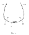
- FIG. 13 and 14 Another example of this type of eyeglasses is shown in Figs. 13 and 14 , which is disclosed in the Japanese Patent Application, Publication No. H06-175085 A1 .
- This example is designed as a pair of sunglasses, and includes a flexible, elastic single lens 31 having an appropriate curved surface, a couple of left and right frames 32 respectively fixed to the upper edges of the respective side end portions of the lens 31, and temples 33 attached to the respective frames 32.
- the upper edge portions of the respective side end portions of the lens 31 have threaded holes (not shown) for screws, and the frames 32 are detachably fixed to the lens 31 with screws 34.
- the document US-A 5,661,536 discloses a unique unitary lens for eyewear which includes right and left lens regions formed of substantially spherical portions.
- the lens provides improved aerodynamics, aesthetic appearance and eye protection for sport eyewear applications.
- the document US-A 4,998,815 relates to sunglasses, which include a glass with a pair of spectacle bows connected thereto by means of a pair of fastening elements.
- the fastening elements each include a front opening defining therein two retaining recessed for convenient connection with either part of snap ends made at both sides of the glass without the use of any screw elements.
- the document US-A 5,387,949 discloses a connector for use in connecting a lens to an earstem, comprising a main body which contains a hinge end and a lens receiving end.
- the connector contains a channel for receiving a portion of the lens.
- the pivot end of the channel contains a recess whereas the locking end of the channel contains a projection.
- the hinge end of the connector is attached to the earstem by a releasable pin connection.
- the lens is connected to the connector by inserting a lens into the channel where the lens is pivoted at the pivot end and then the connector is snapped down to cover over the top edge of the lens.
- the document US-A 5,592,242 relates to sunglasses which include a lens which is replaceable with an alternative one at any time, and wherein frames thereof can be easily attached to and detached from the lens, and the frames can be held stably on the lens while attached thereto.
- the sunglasses include a lens, frames detachably mounted on the respective mounting portions of the lens; and temples attached to the respective frames. When the frames are mounted on the respective mounting portions, holding pieces of each of the frames hold therebetween the corresponding mounting portion.
- the structure in which the frames 32 are detachably fixed to the upper edges of the respective side end portions of the lens 31 with the screws 34 provides sufficient fixing strength but requires time and labor in assembling.
- a lens is detachably fixed, it is not easily detached and attached, and exchanging lenses is troublesome.
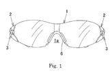
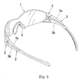
- eyeglasses include a lens 1, a couple of right and left elastically deformable frames 2 attached to side end portions of the lens 1, a couple of right and left temples 3 attached to the respective frames 2.
- a frame fitting portion 4 is provided at each of the side end portions of the lens 1, and a lens fitting hole 5 is provided in a front portion of each of the frames 2. The frame fitting portion 4 fits into the lens fitting hole 5 so that the lens 1 is detachably attached to each of the frames 2.
- the lens fitting hole 5 is formed and defined by an upper wall 2a, a lower wall 2b, an inner wall 2c and an outer wall 2d, and a cutout 13 laterally crossing a center of the inner wall 2c or the outer wall 2d is provided to separate the inner or outer walls 2c or 2d into upper and lower portions.
- cutouts 11 and 12 are formed in front and rear portions of the inner wall (2c) or the outer wall (2d) to a width appropriate to control the degree of elastic deformation of the inner wall (2c) or the outer wall (2d) of the frame (2) for removal and/or attachment of lens (1) and the frames (2).
- a fitting portion 4a is provided at an upper portion of the frame fitting portion 4
- a fitting portion 4b is provided at a lower portion of the frame fitting portion 4
- a fitting portion 5a is provided on an upper face of the lens fitting hole 5
- a fitting portion 5b is provided on a lower face of the lens fitting hole 5.
- the fitting portions 4a and 5a are fittable each other and the fitting portion 4b and 5b are fittable to each other.
- each of the frames 2 has a female temple fitting portion 14 at its upper end and a female temple fitting portion 15 at its lower end
- a front portion of each of the temples 3 has male frame fitting portions 16 and 17.
- the male frame fitting portion 16 can be fitted into and detached from the female temple fitting portion 14 and the male frame fitting portion 17 can be fitted into and detached from the female temple fitting portion 15, and each of the temples 3 is detachably attached to each of the frames 2.
- a fitting portion 14a is provided on the female temple fitting portion 14
- a fitting portion 15a is provided on the female temple fitting portion 15
- a fitting portion 16a is provided on the male frame fitting portion 16
- a fitting portion 17a is provided on the male frame fitting portion 17.
- the fitting portions 14a and 16a are fittable to each other and the fitting portions 15a, 17a are fittable to each other.
- each of the temples 3 is formed of a forked portion with a portion 3a and a portion 3b, which is elastically deformable in a vertical direction.
- the portion 3a has the male frame fitting portion 16 at its front end and the portion 3b has the male frame fitting portion 17 at its front end.
- the female temple fitting portion 14 is horizontally provided with a fitting portion 14b
- a front end of the male frame fitting portion 16 is horizontally provided with a fitting portion 16b to mate with the fitting portion 14b.
- the fitting portions 14b and 16b are fittable to each other.
- the female temple fitting portion 15 is horizontally provided with a fitting portion 15b
- a front end of the male frame fitting portion 17 is horizontally provided with a fitting portion 17b to mate with the fitting portion 15b.
- the fitting portions 15b and 17b are fittable to each other.
- the eyeglasses according to the present invention may have the fitting portion 14b, the fitting portion 15b, the fitting portion 16b and the fitting portion 17b.
- the fitting portions 14b and 16b are fittable to each other, and the fitting portions 15b and 17b are fittable to each other.
- each of the temples 3 is formed of a forked portion 3a and a portion 3b, which is elastically deformable in a vertical direction.
- the fitting between the fitting portions 4a and 5a and the fitting between the fitting portions 4b and 5b are in a male-female manner.
- the fitting between the fitting portions 14a and 16a and the fitting between the fitting portions 15a and 17a are in a male-female manner.
- the fitting between the fitting portions 14b and 16b and the fitting between the fitting portions 15b and 17b are in a male-female manner.
- the volume of the frames is reduced to lighten the eyeglasses as a whole, an effective forward vision of a wearer is guaranteed even when he or she leans forward, and a lens is readily attached to or detached from the frames so as to enable a very easy lens exchange.
- a pair of eyeglasses according to the present invention includes a lens 1, a couple of left and right elastically deformable frames 2 attached to side end portions of the lens 1, and a couple of left and right temples 3 attached to the respective frames 2.
- the lens 1 has a frame fitting portion 4 at each of the side end portions, and each of the frames 2 has a lens fitting hole 5 in a front portion thereof. By fitting the frame fitting portion 4 into the lens fitting hole 5, the front portion of each of the frames 2 is detachably attached to associated side end portion of the lens 1.
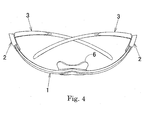
- the lens 1 can be formed of, for example, a single lens or twin lenses made of polycarbonate or any other suitable impact-resistant plastic, or a single lens made of hard glass. As shown in Figs. 1 and 2 , in case the lens 1 is formed of a single lens, a cutout 1a having a substantially V shape is formed at a lower central portion of the lens 1, and a nose pad 6 is removably attached to the cutout portion of the lens 1. In case the lens 1 is formed of twin lenses, a couple of nose pads (not shown) are respectively fixed to at substantially central portions of inner side end portions of the respective twin lenses.
- Each of the side end portions of the lens 1 has a fitting portion 4a at an upper portion and a fitting portion 4b at a lower portion, both of which are formed by cutting the lens 1 to form recesses and projections.
- the fitting portions 4a and 4b respectively detachably fit into associated fitting portion 5a and 5b provided in the lens fitting hole 5 of each of the frames 2, which will be described later.
- the fitting portions 4a and 4b are formed in a female shape
- the fitting portions 5a and 5b are set in a male shape
- the fitting portions 4a and 4b are set in a female shape.
- the portions 4a and 4b and the portions 5a and 5b detachably fit right in a male-female manner.
- Each of the frames 2 is made of nylon or any other suitable synthetic resin, and elastically deformable as described above.
- the lens fitting hole 5 provided at the front portion of each of the frames 2 has a shape defined by an upper wall 2a, a lower wall 2b, an inner wall 2c and an outer wall 2d.
- An upper surface of the lens fitting hole 5 is provided with the fitting portion 5a by raising or depressing the upper surface, into or from which the fitting portion 4a can fit or detach, while a lower surface of the lens fitting hole 5 is provided with the fitting portion 5b similarly, into or from which the fitting portion 4b can fit or detach.
- the lens fitting hole 5 has a vertically elongated shape so as to mate with the frame fitting portion 4 which also has a vertically elongated shape, but not limitative thereto, and can have an arbitrary shape according to the shape of the frame fitting portion 4.
- cutouts 11 and 12 are formed in front and rear portions of the inner wall 2c of each of the frames 2 to narrow the inner wall 2c.
- a cutout 13 laterally crossing the outer wall 2d at the center is formed and separates the outer wall 2d into upper and lower portions.
- the inner wall 2c by being narrowed, becomes readily elastically deformable.
- the inner wall 2c by being thinned as well as narrowed or thinned but not narrowed, also becomes readily elastically deformable.
- the cutout 13 can be filled with a flexible member having rubber elasticity.
- this portion of the wall 2d can be formed with a flexible member having rubber elasticity.
- the inner wall 2c of each of the frames 2 may have a cutout 13 laterally crossing the inner wall 2c at the center to separate it into upper and lower portions, and the outer wall 2d of each of the frames 2 may have cutouts 11 and 12 in front and rear portions of the outer wall 2d to narrow it.
- the outer wall 2d by being narrowed, becomes readily elastically deformable.
- the outer wall 2d by being thinned as well as narrowed or thinned but not narrowed, also becomes readily elastically deformable.
- the cutout 13 can be filled with a flexible member having rubber elasticity.
- the portion of the wall 2c can be formed with a flexible member having rubber elasticity.
- both of the inner wall 2c and the outer wall 2d of each of the frames 2 may respectively have a cutout 13 laterally crossing the inner or outer wall 2c and 2d at the center to separate them into upper and lower portions.
- each of the cutouts 13 can be filled with a flexible member having rubber elasticity.
- the portions of the walls 2c and 2d can be formed with a flexible member having rubber elasticity.
- each of the frames 2 has a female temple fitting portion 14 in an upper portion and another female temple portion 15 in a lower portion, each of which is formed by recessing an inner side of upper or lower rear end portion.
- the front portion of each of the temples 3 has male frame fitting portions 16 and 17 which are protruded in the front portions.
- the front portion of each of the temples 3 is detachably attached to the rear portion of each of the frames 2 in a fashion that the male frame fitting portion 16 fits into the female temple fitting portion 14 and the male frame fitting portion 17 fits into the female temple fitting portion 15 wherein the male frame fitting portions 16 and 17 are respectively detachable from the female temple fitting portions 14 and 15.
- the female temple fitting portions 14 and 15 respectively includes fitting portion 14a and 15a which extend vertical.
- the fitting portion 14a is fittably engaged with a fitting portion 16a provided on the male frame fitting portion 16 of each of the frames 3, while a fitting portion 15a is fittably engaged with a fitting portion 17a provided on the male frame fitting portion 17 of each of the frames 3, which will be described later.
- the fitting portions 14a and 15a are formed in a female shape
- the fitting portion 16a and 17a are set in a male shape
- the fitting portion 16a and 17a are set in a male shape. Therefore the fitting portions associating mutually are engageable with each other in a male-female manner.
- the female temple fitting portion 14 provided in the upper rear portion of the frame 2 is defined by a front wall 2e, a side wall 2f and an upper wall 2g that are perpendicularly adjacent to each other
- the female temple fitting portion 15 provided in the lower rear portion of the frame 2 is defined by a front wall 2e, a side wall 2f, and a lower wall 2h that are perpendicularly adjacent to each other.
- the upper wall 2g of the female temple fitting portion 14 is provided with the fitting portion 14a
- the lower wall 2h of the temple fitting female portion 15 is provided with the fitting portion 15a.
- each of the temples 3 is formed of a forked portion with portions 3a and 3b which is elastically deformable upward and downward.
- the portion 3a of the forked portion has the male frame fitting portion 16 at its front end, while the portion 3b of the forked portion has the male frame fitting portion 17 at its front end.
- the male frame fitting portion 16 has the fitting portion 16a vertically on the upper side, while the male frame fitting portion 17 has the fitting portion 16a vertically on the lower side.
- each of the temples 3 is horizontally pivotable in a range of approximately 90 degrees with respect to the associated frame 2.
- a fitting portion 14b is horizontally provided on the front wall 2e of the female temple fitting female portion 14, and a fitting portion 15b is horizontally provided on the front wall 2e of the female temple fitting portion 15.
- a fitting portion 16b to mate with the fitting portion 14b is horizontally provided in the front end of the male frame fitting portion 16, and a fitting portion 17b to mate with the fitting portion 15b is horizontally provided in the front end of the male frame fitting portion 17.
- the fitting portion 14b detachably fits into the fitting portion 16b, and the fitting portion 15b detachably fits into the fitting portion 17b.
- the front wall 2e of the female temple fitting portion 14 and the front end of the male frame fitting portion 16 may have the fitting portions 14b and 16b horizontally, and thereby the fitting portion 14b may detachably fit into the fitting portion 16b.
- the front wall 2e of the female temple fitting portion 15 and the front end of the male frame fitting portion 17 may have the fitting portions 15b and 17b horizontally, and the fitting portion 15b may detachably fit into the fitting portion 17b.
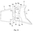
- FIG. 10 A still further alternative is shown in Fig. 10 , where the front portion of each of the temples 3 has no forked portion with 3a and 3b.
- each of the temples 3 is provided with a male frame fitting portion 18 which corresponds to either of the fitting portions 16b and 17b, and the front end of the fitting portion 18 has a fitting portion 18b which corresponds to either of the fitting portions 16b and 17b.
- the female temple fitting portions 14 and 15 may be joined to form a female temple fitting portion 19 which has a fitting portion 19b corresponding to either of the fitting portions 14b and 15b on the front wall 2e, and thereby the fitting portions 18b and 19b may fittably engage with each other.
- the male frame fitting portion 18 is provided with a fitting portion 18a corresponding to the fitting portion 16a on its upper portion and another fitting potion 18a corresponding to the fitting portion 17a on its lower portion.
- the female temple fitting portion 19 is defined by the front wall 2e, the side wall 2f, the upper wall 2g and the lower wall 2h that are perpendicularly adjacent to each other.
- the upper wall 2g of the female temple fitting portion 19 is provided with a fitting portion 19a corresponding to the fitting portion 14a
- the lower wall 2h of the female temple fitting portion 19 is provided with another fitting portion 19a corresponding to the fitting portion 15a.
- the fitting portion 14b, 15b and 19b are formed in a male shape
- the fitting portions 16b, 17b and 18b are set in a female shape
- the fitting portions 16b, 17b, and 18b are set in a male shape. Therefore the fitting portions associating mutually are engageably in a male-female manner.
- Each of the temples 3 horizontally pivots with respect to the associated frame 2 in a manner wherein the fitting portion 14b on the front wall 2e of the female temple fitting portion 14 fits into the fitting portion 16b on the front end of the male fitting portion 16 and is slidably in contact with the fitting portion 16b, the fitting portion 15b on the front wall 2e of the female temple fitting portion 15 fits into the fitting portion 17b on the front end of the male frame fitting portion 17 and is slidably in contact with the fitting portion 17b, and thereby the temple 3 does not wobble with respect to the frame 2.
- the engagements between the fitting portions 14b and 16b and between the fitting portions 15b and 17b are released.
- This configuration is advantageous in removing the temple 3 from the associated frame 2, which will be described in detail later. Briefly, pivoting the temple 3 by approximately 90 degrees before removal will eliminate the resistance between the fitting portions 14b and 16b as well as the resistance between the fitting portions 15b and 17b and thus facilitate easy release between the temple 3 and the frame 2.
- a couple of left and right frames 2 are detachably attached respectively to the right and left side end portions of the lens 1 so that the volume as well as the weight of the frames 2 can be reduced, which consequently reduces the weight of the eyeglasses.
- the left and right frames 2 will not narrow the forward vision of a wearer, but guarantee the effective forward vision when he or she leans forward.
- the lens 1 is removed from each of the frames 2 in the following manner:
- the eyeglasses being in the state shown in Figs. 5A and 5B , a user pinches the inner and outer walls 2c and 2d of one of the frames 2 with a thumb and a finger or fingers of one hand, and the lens 1 with those of the other hand, and then pulls the lens 1 in the removal direction from the frame 2.
- the inner wall 2c of the frame 2 elastically deforms as shown in Fig. 6B and the gap between the fitting portions 5a and 5b of the frame 2 increases.
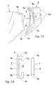
- the lens 1 can be attached to each of the frames 2 in the following manner: The eyeglasses being in the state shown in Figs. 7A and 7B , the user pinches the inner and outer walls 2c and 2d of the frame 2 with a thumb and a finger or fingers of one hand, and the lens 1 with those of the other hand, and pushes the frame fitting portion 4 of the lens 1 toward into the lens fitting hole 5 of the frame 2.
- the fitting portion 4a of the lens 1 presses against the fitting portion 5a of the frame 2
- the fitting portion 4b of the lens 1 presses against the fitting portion 5b of the frame 2
- the inner wall 2c of the frame 2 elastically deforms as shown in Fig. 6B .
- the gap between the fitting portions 5a and 5b of the frame 2 increases, and this facilitates the fitting portions 4a and 4b of the lens 1 to fit into the fitting portions 5a and 5b respectively.
- the lens 1 can be readily attached to the frame 2 as shown in Figs. 5A and 5B .
- the friction resistance between the fitting portions 4a and 5a and between the fitting portions 4b and 5b is reduced. As a result, these portions will be prevented from wearing out and unwanted deforming, and hence the durability is improved.
- the degree of elastic deformation of the inner wall 2c of the frame 2 can be controlled by adjusting the width and/or the thickness of the inner wall 2c of the frame 2.
- the width and/or the thickness thereof may be set at a size appropriate for removal and/or attachment of the lens 1 and the frames 2 in accordance with the application of the eyeglasses.
- each of the temples 3 is removed from the associated frame 2 in the following manner:
- the frame 2 and the temple 3 being in the state shown in Fig. 8 , a user pinches the frame 2 with a thumb and a finger or fingers of one hand, and pinches and presses the portions 3a and 3b of the forked portion of the temple 3 from above and below with a thumb and a finger or fingers of the other hand.
- the gap between the portions 3a and 3b decreases, and this releases the fitting portion 16a of the male frame fitting portion 16 from the fitting portion 14a of the female temple fitting portion 14 and the fitting portion 17a of the male frame fitting portion 17 from the fitting portion 15a of the female temple fitting portion 15.
- the temple 3 is pulled apart from the frame 2, and it can be readily removed therefrom as shown in Fig. 9 .
- each of the temples 3 is attached to the associated frame 2 in the following manner: The frame 2 and the temple 3 being in the state shown in Fig. 9 , a user pinches the frame 2 with a thumb and a finger or fingers of one hand, and pinches and presses the portions 3a and 3b of the forked portion of the temple 3 from above and below with a thumb and a finger or fingers of the other hand. Then the gap between the portions 3a and 3b decreases.
- the fitting portion 16a of the male frame fitting portion 16 is positioned to align with the fitting portion 14a of the female temple fitting portion 14, and the fitting portion 17a of the male frame fitting portion 17 is positioned to align with the fitting portion 15a of the female temple fitting portion 15.
- the user ceases pressing to let the portions 3a and 3b of the forked portion restore to the original state with a widened gap, and thereby the fitting portion 16a fits into the fitting portion 14a and the fitting portion 17a fits into the fitting portion 15a.
- the fitting portion 14b on the front wall 2e of the female temple fitting portion 14 fits into the fitting portion 16b in the front end portion of the male frame fitting portion 16
- the fitting portion 15b on the front wall 2e of the female temple fitting portion 15 fits into the fitting portion 17b in the front end of the male frame fitting portion 17, whereby each of temples 3 can be readily attached to the associated frame 2, as shown in Fig. 8 .
- each of the temples 3 attached to the associated frame 2 can horizontally pivot but will not wobble with respect to the frame 2, as described above. Further, the portions where the fitting portions 16a and 17a respectively fit into the fitting portions 14a and 15a and the portions where the fitting portions 14b and 15b respectively fit into the fitting portions 16b and 17b are not exposed outside and thereby will unlikely be affected by any surface treatment, such as painting. As a result, condition of an appropriate fitting engagement can be maintained.
Landscapes
- Physics & Mathematics (AREA)
- Health & Medical Sciences (AREA)
- General Physics & Mathematics (AREA)
- Ophthalmology & Optometry (AREA)
- Optics & Photonics (AREA)
- Eyeglasses (AREA)
- Mirrors, Picture Frames, Photograph Stands, And Related Fastening Devices (AREA)
Claims (12)
- Lunettes comprenant :une lentille (1) ;un couple de montures (2) gauche et droite déformables élastiquement fixées à des parties terminales latérales de la lentille (1) ;un couple de tempes (3) gauche et droite fixées aux montures respectives (2) ;une partie d'adaptation de la monture (4) prévue sur chacune des parties terminales latérales de la lentille (1) ;un orifice d'adaptation de la lentille (5) prévu sur une partie avant de chacune des montures (2) ; etdans lesquelles la partie d'adaptation de la monture (4) s'adapte à l'orifice d'adaptation de la lentille (5) de sorte que la lentille (1) soit fixée de manière amovible à chacune des montures (2) ; etl'orifice d'adaptation de la lentille (5) est défini par une paroi supérieure (2 a),une paroi inférieure (2 b), une paroi intérieure (2 c) et une paroi extérieure (2 d),caractérisées en ce qu'une découpe (13) traversant latéralement un centre de la paroi intérieure (2 c) ou de la paroi extérieure (2 d) est prévue afin de séparer la paroi intérieure (2 c) ou la paroi extérieure (2 d) en une partie supérieure et une partie inférieure etdes découpes (11) sont (12) formées à l'avant et à l'arrière de la paroi extérieure respective (2 d) ou de la paroi intérieure (2 c) de chacune des montures (2) afin de limiter la paroi extérieure (2 d) ou la paroi intérieure (2 c) respectivement à une largeur appropriée afin de contrôler le degré de déformation élastique de la paroi extérieure (2 d) ou de la paroi intérieure (2 c) de la monture (2) pour un retrait et/ou une fixation de la lentille (1) et des montures (2).
- Lunettes selon la revendication 1, comprenant en outre :une partie d'adaptation 4 a (4 a) prévue sur une partie supérieure de la partie d'adaptation de la monture (4) ;une partie d'adaptation 4 b (4 b) prévue sur une partie inférieure de la partie d'adaptation de la monture (4) ;une partie d'adaptation 5 a (5 a) prévue sur une face supérieure de l'orifice d'adaptation de la lentille (5) ;une partie d'adaptation 5 b (5 b) prévue sur une face inférieure de l'orifice d'adaptation de la lentille (5) ; etdans lesquelles les parties d'adaptation 4 a et 5 a s'adaptent l'une à l'autre au même titre que les parties d'adaptation 4 b et 5 b.
- Lunettes selon l'une quelconque des revendications 1 ou 2, dans lesquelles une partie arrière de chacune des montures (2) possède une partie d'adaptation de la tempe femelle (14) à une extrémité supérieure et une partie d'adaptation de la tempe femelle (15) à une extrémité inférieure, une partie avant de chacune des tempes (3) possédant des parties d'adaptation de la monture mâles (16, 17), la partie d'adaptation de la monture mâle (16) pouvant s'adapter à et étant détachable de la partie d'adaptation femelle (14), la partie d'adaptation de la monture mâle (17) étant adaptable à et étant détachable de la partie d'adaptation femelle (15), de sorte que chacune des tempes (3) est fixée de manière amovible à l'une ou l'autre parmi les montures (2).
- Lunettes selon la revendication 3, dans lesquelles une partie d'adaptation 14 a (14 a) est prévue sur la partie d'adaptation de la tempe femelle (14), une partie d'adaptation 15 a (15 a) étant prévue sur la partie d'adaptation de la tempe femelle (15) et une partie d'adaptation 16 a (16 a) étant prévue sur la partie d'adaptation de la monture mâle (16), une partie d'adaptation 17 a (17 a) étant prévue sur la partie d'adaptation de la monture mâle (17), dans lesquelles les parties d'adaptation 14 a et 16 a s'adaptent l'une à l'autre au même titre que les parties d'adaptation 15 a et 17 a.
- Lunettes selon la revendication 3 ou 4, dans lesquelles la partie avant de chacune des tempes (3) est formée en qualité de partie fourchue avec une partie (3 a) et une partie (3 b), la partie (3 a) possédant une partie d'adaptation de la monture mâle (16) à une extrémité avant et la partie (3 b) possédant une partie d'adaptation de la monture mâle (17) à une extrémité avant.
- Lunettes selon la revendication 4 ou 5, dans lesquelles la partie d'adaptation de la tempe femelle (14) est dotée horizontalement d'une partie d'adaptation 14 b (14 b), une extrémité avant de la partie d'adaptation de la monture mâle (16) étant dotée horizontalement d'une partie d'adaptation 16 b (16 b) afin de s'accoupler avec la partie d'adaptation 14 b (14 b), les parties d'adaptation 14 b et 16 b étant adaptées l'une à l'autre.
- Lunettes selon la revendication 4 ou 5, dans lesquelles la partie d'adaptation de la tempe femelle (15) est dotée horizontalement d'une partie d'adaptation 15 b (15 b), une extrémité avant de la partie d'adaptation de la monture mâle (17) étant dotée horizontalement d'une partie d'adaptation 17 b (17 b) afin de s'accoupler avec la partie d'adaptation 15 b (15 b), les parties d'adaptation 15 b et 17 b étant adaptées l'une à l'autre.
- Lunettes selon la revendication 4 ou 5, dans lesquelles la partie d'adaptation de la tempe femelle (14) est horizontalement dotée d'une partie d'adaptation 14 b (14 b), la partie d'adaptation de la tempe femelle (15) étant horizontalement dotée d'une partie d'adaptation 15 b (15 b), une extrémité avant de la partie d'adaptation de la monture mâle (16) étant horizontalement dotée d'une partie d'adaptation 16 b (16 b) afin de s'accoupler avec la partie d'adaptation 14 b (14 b), une extrémité avant de la partie d'adaptation de la monture (17) étant horizontalement dotée d'une partie d'adaptation 17 b (17 b) afin de s'accoupler avec la partie d'adaptation 15 b (15 b), les parties d'adaptation 14 b et 16 b étant adaptées l'une à l'autre, au même titre que les parties d'adaptation 15 b et 17 b.
- Lunettes selon l'une quelconque des revendications 1 à 8, dans lesquelles la partie avant de chacune des tempes (3) est constituée d'une partie fourchue (3 a) et d'une partie (3 b) déformable élastiquement dans le sens vertical.
- Lunettes selon la revendication 2, dans lesquelles l'accouplement entre les parties d'adaptation 4 a et 5 a ainsi que l'accouplement entre les parties d'adaptation 4 b et 5 b s'effectuent de manière mâle-femelle.
- Lunettes selon la revendication 4, dans lesquelles l'accouplement entre les parties d'adaptation 14 a et 16 a ainsi que l'accouplement entre les parties d'adaptation 15 a et 17 a s'effectuent de manière mâle-femelle.
- Lunettes selon la revendication 8, dans lesquelles l'accouplement entre les parties d'adaptation 14 b et 16 b ainsi que l'accouplement entre les parties d'adaptation 15 b et 17 b s'effectuent de manière mâle-femelle.
Applications Claiming Priority (1)
| Application Number | Priority Date | Filing Date | Title |
|---|---|---|---|
| JP2008218780A JP5071907B2 (ja) | 2008-08-27 | 2008-08-27 | 眼鏡 |
Publications (2)
| Publication Number | Publication Date |
|---|---|
| EP2159623A1 EP2159623A1 (fr) | 2010-03-03 |
| EP2159623B1 true EP2159623B1 (fr) | 2014-10-08 |
Family
ID=41119545
Family Applications (1)
| Application Number | Title | Priority Date | Filing Date |
|---|---|---|---|
| EP09168691.5A Not-in-force EP2159623B1 (fr) | 2008-08-27 | 2009-08-26 | Lunettes |
Country Status (5)
| Country | Link |
|---|---|
| US (1) | US8292425B2 (fr) |
| EP (1) | EP2159623B1 (fr) |
| JP (1) | JP5071907B2 (fr) |
| KR (1) | KR101529326B1 (fr) |
| CN (1) | CN101661165B (fr) |
Cited By (1)
| Publication number | Priority date | Publication date | Assignee | Title |
|---|---|---|---|---|
| DE202019104575U1 (de) | 2019-08-20 | 2019-10-30 | Michael Pachleitner Group GmbH | Brille |
Families Citing this family (19)
| Publication number | Priority date | Publication date | Assignee | Title |
|---|---|---|---|---|
| JP5212948B2 (ja) | 2009-04-24 | 2013-06-19 | 山本光学株式会社 | 眼鏡 |
| US8894200B2 (en) | 2010-06-30 | 2014-11-25 | Addo Industries, Llc | Innovative and aesthetic alternative to traditional spectacle correction |
| KR20120048784A (ko) * | 2010-11-08 | 2012-05-16 | 기 연 김 | 모자부착 겸용 선글라스 |
| JP5690357B2 (ja) * | 2011-01-27 | 2015-03-25 | ミドリ安全株式会社 | 眼鏡 |
| ITPD20110225A1 (it) * | 2011-07-05 | 2013-01-06 | Rudy Project S R L | Dispositivo per il fissaggio rimovibile di elementi di montatura a lenti di occhiali ed occhiali a lenti intercambiabili includenti detto dispositivo di fissaggio |
| US9256080B2 (en) * | 2011-11-08 | 2016-02-09 | Tifosi Optics Inc. | Receptor and lock for glasses with removable lenses |
| US8613515B2 (en) * | 2011-11-08 | 2013-12-24 | Tifosi Optics Inc. | Lens receptor lock for glasses |
| CN102591034B (zh) * | 2012-03-04 | 2013-11-27 | 深圳市欧帝光学有限公司 | 一种眼镜 |
| JP2014052396A (ja) * | 2012-09-05 | 2014-03-20 | Nakanishi Opt:Kk | 眼鏡フレームのテンプル連結構造 |
| FR3013464A1 (fr) * | 2013-11-18 | 2015-05-22 | Cfdg | Ensemble articule de deux pieces |
| USD735796S1 (en) * | 2013-11-19 | 2015-08-04 | Tifosi Optics, Inc. | Configurable glasses |
| USD735800S1 (en) * | 2013-11-19 | 2015-08-04 | Tifosi Optics, Inc. | Temple for glasses |
| KR102258256B1 (ko) * | 2014-01-31 | 2021-05-28 | 야마모토 고가쿠 가부시키가이샤 | 고글 |
| US10261338B2 (en) | 2015-01-15 | 2019-04-16 | Addo Industries, Llc | Eyewear comprising suspension system for nose and ears |
| CN106154578A (zh) * | 2015-04-01 | 2016-11-23 | 江苏洪旭光电科技有限公司 | 一种易拆卸太阳眼镜 |
| CN106019623A (zh) * | 2016-07-29 | 2016-10-12 | 吕栋 | 多功能眼镜 |
| USD802651S1 (en) * | 2016-09-01 | 2017-11-14 | Oakley, Inc. | Eyeglass component |
| AT519724B1 (de) * | 2017-03-09 | 2021-09-15 | Pocket Sky Og | Brille |
| EP3783419B1 (fr) | 2019-08-20 | 2022-06-08 | MPG GmbH | Lunettes |
Family Cites Families (19)
| Publication number | Priority date | Publication date | Assignee | Title |
|---|---|---|---|---|
| FR954467A (fr) * | 1950-01-03 | |||
| US4824233A (en) | 1985-01-11 | 1989-04-25 | Jannard James H | Multi-component sunglasses |
| JPH0542419Y2 (fr) * | 1988-04-27 | 1993-10-26 | ||
| JPH0314209A (ja) | 1989-06-13 | 1991-01-22 | Murata Mfg Co Ltd | 積層型電子部品 |
| JPH0314209U (fr) * | 1989-06-27 | 1991-02-13 | ||
| US4998815A (en) * | 1989-09-27 | 1991-03-12 | Lin David J T | Sunglass frame structure |
| US5387949A (en) * | 1992-01-29 | 1995-02-07 | Oakley, Inc. | Eyeglass connection device |
| JP3014209B2 (ja) | 1992-04-07 | 2000-02-28 | 三菱電機株式会社 | 画像情報提示装置 |
| JP2986314B2 (ja) | 1992-09-14 | 1999-12-06 | 山本光学株式会社 | 眼 鏡 |
| US5592242A (en) * | 1993-10-29 | 1997-01-07 | O.G.K. Hanbai Co., Ltd. | Eyeglass connection device |
| US5555038A (en) * | 1994-10-28 | 1996-09-10 | Bausch & Lomb Incorporated | Unitary lens for eyewear |
| TW347876U (en) | 1996-05-17 | 1998-12-11 | Persaf Corp | Angle adjusting structure for spectacles lenses |
| TW348859U (en) | 1996-09-13 | 1998-12-21 | Jin-Lung Chen | Improvement for spectacles structure |
| TW341335U (en) | 1996-10-03 | 1998-09-21 | A&V Mede Group Co Ltd | A glasses lens angle regulation structure |
| TW335908U (en) | 1997-07-09 | 1998-07-01 | Gazelle Corp | The structure of a turntable and retractable glasses hinge |
| TW333341U (en) | 1997-10-15 | 1998-06-01 | Win Win Spectacles Co Ltd | Improved eyeglasses |
| DE20207180U1 (de) * | 2002-05-07 | 2002-07-25 | Uvex Arbeitsschutz GmbH, 90766 Fürth | Brille, insbesondere Schutzbrille |
| US7029115B2 (en) * | 2004-03-19 | 2006-04-18 | Michael Toulch | Rimless eyeglasses |
| KR100613409B1 (ko) | 2004-07-23 | 2006-08-17 | 백상현 | 프레임을 갖는 모자 부착 겸용 안경 |
-
2008
- 2008-08-27 JP JP2008218780A patent/JP5071907B2/ja active Active
-
2009
- 2009-08-25 KR KR1020090078567A patent/KR101529326B1/ko not_active Expired - Fee Related
- 2009-08-26 EP EP09168691.5A patent/EP2159623B1/fr not_active Not-in-force
- 2009-08-27 CN CN2009101683620A patent/CN101661165B/zh not_active Expired - Fee Related
- 2009-08-27 US US12/548,669 patent/US8292425B2/en active Active
Cited By (1)
| Publication number | Priority date | Publication date | Assignee | Title |
|---|---|---|---|---|
| DE202019104575U1 (de) | 2019-08-20 | 2019-10-30 | Michael Pachleitner Group GmbH | Brille |
Also Published As
| Publication number | Publication date |
|---|---|
| US20100053545A1 (en) | 2010-03-04 |
| CN101661165B (zh) | 2012-12-26 |
| EP2159623A1 (fr) | 2010-03-03 |
| KR101529326B1 (ko) | 2015-06-16 |
| JP5071907B2 (ja) | 2012-11-14 |
| CN101661165A (zh) | 2010-03-03 |
| KR20100025481A (ko) | 2010-03-09 |
| US8292425B2 (en) | 2012-10-23 |
| JP2010054738A (ja) | 2010-03-11 |
Similar Documents
| Publication | Publication Date | Title |
|---|---|---|
| US8292425B2 (en) | Eyeglasses | |
| EP1960823B1 (fr) | Lunettes a monture a pinces et verres | |
| US6959988B1 (en) | Eyewear having detachable lens retaining member | |
| US6991333B2 (en) | Eyewear with replaceable lens | |
| US7241007B2 (en) | Convertible eyewear | |
| US5189447A (en) | Integrated field eyewear system | |
| JP4310649B2 (ja) | 複合用途対応型眼鏡 | |
| US7461935B2 (en) | Eyewear with inner and outer frame lens | |
| US7645039B2 (en) | Eyewear having interchangeable lenses/temples | |
| EP1730578B1 (fr) | Lunettes | |
| US6102542A (en) | Eyeglass assembly | |
| US9535261B2 (en) | Eyeglass temple having an auxiliary cushion frame | |
| US7661816B2 (en) | Eyeglasses assembly | |
| US20070008482A1 (en) | Eyeglasses | |
| US6345892B2 (en) | Sunglasses with readily detachable lens | |
| US20060244897A1 (en) | Modular eyewear | |
| CN113031270B (zh) | 一种眼镜 | |
| US20090027615A1 (en) | Connecting structure for glass frame and wearing portion | |
| EP3479165B1 (fr) | Lunettes à lentilles à enclenchement facile | |
| KR20230013327A (ko) | 안경의 교환식 안경다리 | |
| JPH0732628U (ja) | レンズ着脱式眼鏡 | |
| US7971992B1 (en) | Eyewear with interchangeable components |
Legal Events
| Date | Code | Title | Description |
|---|---|---|---|
| PUAI | Public reference made under article 153(3) epc to a published international application that has entered the european phase |
Free format text: ORIGINAL CODE: 0009012 |
|
| AK | Designated contracting states |
Kind code of ref document: A1 Designated state(s): AT BE BG CH CY CZ DE DK EE ES FI FR GB GR HR HU IE IS IT LI LT LU LV MC MK MT NL NO PL PT RO SE SI SK SM TR |
|
| 17P | Request for examination filed |
Effective date: 20100902 |
|
| 17Q | First examination report despatched |
Effective date: 20120808 |
|
| GRAP | Despatch of communication of intention to grant a patent |
Free format text: ORIGINAL CODE: EPIDOSNIGR1 |
|
| RIC1 | Information provided on ipc code assigned before grant |
Ipc: G02C 1/02 20060101AFI20140219BHEP Ipc: G02C 5/22 20060101ALI20140219BHEP Ipc: G02C 5/14 20060101ALI20140219BHEP Ipc: G02C 5/10 20060101ALI20140219BHEP |
|
| INTG | Intention to grant announced |
Effective date: 20140326 |
|
| GRAS | Grant fee paid |
Free format text: ORIGINAL CODE: EPIDOSNIGR3 |
|
| GRAA | (expected) grant |
Free format text: ORIGINAL CODE: 0009210 |
|
| AK | Designated contracting states |
Kind code of ref document: B1 Designated state(s): AT BE BG CH CY CZ DE DK EE ES FI FR GB GR HR HU IE IS IT LI LT LU LV MC MK MT NL NO PL PT RO SE SI SK SM TR |
|
| REG | Reference to a national code |
Ref country code: GB Ref legal event code: FG4D |
|
| REG | Reference to a national code |
Ref country code: AT Ref legal event code: REF Ref document number: 690934 Country of ref document: AT Kind code of ref document: T Effective date: 20141015 Ref country code: CH Ref legal event code: EP |
|
| REG | Reference to a national code |
Ref country code: IE Ref legal event code: FG4D |
|
| REG | Reference to a national code |
Ref country code: DE Ref legal event code: R096 Ref document number: 602009027050 Country of ref document: DE Effective date: 20141120 |
|
| REG | Reference to a national code |
Ref country code: NL Ref legal event code: VDEP Effective date: 20141008 |
|
| REG | Reference to a national code |
Ref country code: AT Ref legal event code: MK05 Ref document number: 690934 Country of ref document: AT Kind code of ref document: T Effective date: 20141008 |
|
| REG | Reference to a national code |
Ref country code: LT Ref legal event code: MG4D |
|
| PG25 | Lapsed in a contracting state [announced via postgrant information from national office to epo] |
Ref country code: NL Free format text: LAPSE BECAUSE OF FAILURE TO SUBMIT A TRANSLATION OF THE DESCRIPTION OR TO PAY THE FEE WITHIN THE PRESCRIBED TIME-LIMIT Effective date: 20141008 |
|
| PG25 | Lapsed in a contracting state [announced via postgrant information from national office to epo] |
Ref country code: FI Free format text: LAPSE BECAUSE OF FAILURE TO SUBMIT A TRANSLATION OF THE DESCRIPTION OR TO PAY THE FEE WITHIN THE PRESCRIBED TIME-LIMIT Effective date: 20141008 Ref country code: PT Free format text: LAPSE BECAUSE OF FAILURE TO SUBMIT A TRANSLATION OF THE DESCRIPTION OR TO PAY THE FEE WITHIN THE PRESCRIBED TIME-LIMIT Effective date: 20150209 Ref country code: LT Free format text: LAPSE BECAUSE OF FAILURE TO SUBMIT A TRANSLATION OF THE DESCRIPTION OR TO PAY THE FEE WITHIN THE PRESCRIBED TIME-LIMIT Effective date: 20141008 Ref country code: IS Free format text: LAPSE BECAUSE OF FAILURE TO SUBMIT A TRANSLATION OF THE DESCRIPTION OR TO PAY THE FEE WITHIN THE PRESCRIBED TIME-LIMIT Effective date: 20150208 Ref country code: ES Free format text: LAPSE BECAUSE OF FAILURE TO SUBMIT A TRANSLATION OF THE DESCRIPTION OR TO PAY THE FEE WITHIN THE PRESCRIBED TIME-LIMIT Effective date: 20141008 Ref country code: NO Free format text: LAPSE BECAUSE OF FAILURE TO SUBMIT A TRANSLATION OF THE DESCRIPTION OR TO PAY THE FEE WITHIN THE PRESCRIBED TIME-LIMIT Effective date: 20150108 |
|
| PG25 | Lapsed in a contracting state [announced via postgrant information from national office to epo] |
Ref country code: LV Free format text: LAPSE BECAUSE OF FAILURE TO SUBMIT A TRANSLATION OF THE DESCRIPTION OR TO PAY THE FEE WITHIN THE PRESCRIBED TIME-LIMIT Effective date: 20141008 Ref country code: HR Free format text: LAPSE BECAUSE OF FAILURE TO SUBMIT A TRANSLATION OF THE DESCRIPTION OR TO PAY THE FEE WITHIN THE PRESCRIBED TIME-LIMIT Effective date: 20141008 Ref country code: PL Free format text: LAPSE BECAUSE OF FAILURE TO SUBMIT A TRANSLATION OF THE DESCRIPTION OR TO PAY THE FEE WITHIN THE PRESCRIBED TIME-LIMIT Effective date: 20141008 Ref country code: SE Free format text: LAPSE BECAUSE OF FAILURE TO SUBMIT A TRANSLATION OF THE DESCRIPTION OR TO PAY THE FEE WITHIN THE PRESCRIBED TIME-LIMIT Effective date: 20141008 Ref country code: AT Free format text: LAPSE BECAUSE OF FAILURE TO SUBMIT A TRANSLATION OF THE DESCRIPTION OR TO PAY THE FEE WITHIN THE PRESCRIBED TIME-LIMIT Effective date: 20141008 Ref country code: GR Free format text: LAPSE BECAUSE OF FAILURE TO SUBMIT A TRANSLATION OF THE DESCRIPTION OR TO PAY THE FEE WITHIN THE PRESCRIBED TIME-LIMIT Effective date: 20150109 Ref country code: CY Free format text: LAPSE BECAUSE OF FAILURE TO SUBMIT A TRANSLATION OF THE DESCRIPTION OR TO PAY THE FEE WITHIN THE PRESCRIBED TIME-LIMIT Effective date: 20141008 |
|
| REG | Reference to a national code |
Ref country code: DE Ref legal event code: R097 Ref document number: 602009027050 Country of ref document: DE |
|
| PG25 | Lapsed in a contracting state [announced via postgrant information from national office to epo] |
Ref country code: EE Free format text: LAPSE BECAUSE OF FAILURE TO SUBMIT A TRANSLATION OF THE DESCRIPTION OR TO PAY THE FEE WITHIN THE PRESCRIBED TIME-LIMIT Effective date: 20141008 Ref country code: CZ Free format text: LAPSE BECAUSE OF FAILURE TO SUBMIT A TRANSLATION OF THE DESCRIPTION OR TO PAY THE FEE WITHIN THE PRESCRIBED TIME-LIMIT Effective date: 20141008 Ref country code: DK Free format text: LAPSE BECAUSE OF FAILURE TO SUBMIT A TRANSLATION OF THE DESCRIPTION OR TO PAY THE FEE WITHIN THE PRESCRIBED TIME-LIMIT Effective date: 20141008 Ref country code: SK Free format text: LAPSE BECAUSE OF FAILURE TO SUBMIT A TRANSLATION OF THE DESCRIPTION OR TO PAY THE FEE WITHIN THE PRESCRIBED TIME-LIMIT Effective date: 20141008 Ref country code: RO Free format text: LAPSE BECAUSE OF FAILURE TO SUBMIT A TRANSLATION OF THE DESCRIPTION OR TO PAY THE FEE WITHIN THE PRESCRIBED TIME-LIMIT Effective date: 20141008 |
|
| PLBE | No opposition filed within time limit |
Free format text: ORIGINAL CODE: 0009261 |
|
| STAA | Information on the status of an ep patent application or granted ep patent |
Free format text: STATUS: NO OPPOSITION FILED WITHIN TIME LIMIT |
|
| 26N | No opposition filed |
Effective date: 20150709 |
|
| PG25 | Lapsed in a contracting state [announced via postgrant information from national office to epo] |
Ref country code: SI Free format text: LAPSE BECAUSE OF FAILURE TO SUBMIT A TRANSLATION OF THE DESCRIPTION OR TO PAY THE FEE WITHIN THE PRESCRIBED TIME-LIMIT Effective date: 20141008 |
|
| PG25 | Lapsed in a contracting state [announced via postgrant information from national office to epo] |
Ref country code: LU Free format text: LAPSE BECAUSE OF FAILURE TO SUBMIT A TRANSLATION OF THE DESCRIPTION OR TO PAY THE FEE WITHIN THE PRESCRIBED TIME-LIMIT Effective date: 20150826 Ref country code: MC Free format text: LAPSE BECAUSE OF FAILURE TO SUBMIT A TRANSLATION OF THE DESCRIPTION OR TO PAY THE FEE WITHIN THE PRESCRIBED TIME-LIMIT Effective date: 20141008 |
|
| REG | Reference to a national code |
Ref country code: CH Ref legal event code: PL |
|
| GBPC | Gb: european patent ceased through non-payment of renewal fee |
Effective date: 20150826 |
|
| PG25 | Lapsed in a contracting state [announced via postgrant information from national office to epo] |
Ref country code: CH Free format text: LAPSE BECAUSE OF NON-PAYMENT OF DUE FEES Effective date: 20150831 Ref country code: LI Free format text: LAPSE BECAUSE OF NON-PAYMENT OF DUE FEES Effective date: 20150831 |
|
| REG | Reference to a national code |
Ref country code: DE Ref legal event code: R082 Ref document number: 602009027050 Country of ref document: DE Representative=s name: SCHWABE SANDMAIR MARX PATENTANWAELTE RECHTSANW, DE Ref country code: DE Ref legal event code: R082 Ref document number: 602009027050 Country of ref document: DE Representative=s name: SSM SANDMAIR PATENTANWAELTE RECHTSANWALT PARTN, DE |
|
| REG | Reference to a national code |
Ref country code: IE Ref legal event code: MM4A |
|
| REG | Reference to a national code |
Ref country code: FR Ref legal event code: ST Effective date: 20160429 |
|
| PG25 | Lapsed in a contracting state [announced via postgrant information from national office to epo] |
Ref country code: GB Free format text: LAPSE BECAUSE OF NON-PAYMENT OF DUE FEES Effective date: 20150826 Ref country code: IE Free format text: LAPSE BECAUSE OF NON-PAYMENT OF DUE FEES Effective date: 20150826 |
|
| PG25 | Lapsed in a contracting state [announced via postgrant information from national office to epo] |
Ref country code: FR Free format text: LAPSE BECAUSE OF NON-PAYMENT OF DUE FEES Effective date: 20150831 |
|
| PG25 | Lapsed in a contracting state [announced via postgrant information from national office to epo] |
Ref country code: MT Free format text: LAPSE BECAUSE OF FAILURE TO SUBMIT A TRANSLATION OF THE DESCRIPTION OR TO PAY THE FEE WITHIN THE PRESCRIBED TIME-LIMIT Effective date: 20141008 |
|
| PG25 | Lapsed in a contracting state [announced via postgrant information from national office to epo] |
Ref country code: HU Free format text: LAPSE BECAUSE OF FAILURE TO SUBMIT A TRANSLATION OF THE DESCRIPTION OR TO PAY THE FEE WITHIN THE PRESCRIBED TIME-LIMIT; INVALID AB INITIO Effective date: 20090826 Ref country code: BG Free format text: LAPSE BECAUSE OF FAILURE TO SUBMIT A TRANSLATION OF THE DESCRIPTION OR TO PAY THE FEE WITHIN THE PRESCRIBED TIME-LIMIT Effective date: 20141008 Ref country code: SM Free format text: LAPSE BECAUSE OF FAILURE TO SUBMIT A TRANSLATION OF THE DESCRIPTION OR TO PAY THE FEE WITHIN THE PRESCRIBED TIME-LIMIT Effective date: 20141008 |
|
| PG25 | Lapsed in a contracting state [announced via postgrant information from national office to epo] |
Ref country code: TR Free format text: LAPSE BECAUSE OF FAILURE TO SUBMIT A TRANSLATION OF THE DESCRIPTION OR TO PAY THE FEE WITHIN THE PRESCRIBED TIME-LIMIT Effective date: 20141008 |
|
| PG25 | Lapsed in a contracting state [announced via postgrant information from national office to epo] |
Ref country code: BE Free format text: LAPSE BECAUSE OF FAILURE TO SUBMIT A TRANSLATION OF THE DESCRIPTION OR TO PAY THE FEE WITHIN THE PRESCRIBED TIME-LIMIT Effective date: 20141008 |
|
| PG25 | Lapsed in a contracting state [announced via postgrant information from national office to epo] |
Ref country code: MK Free format text: LAPSE BECAUSE OF FAILURE TO SUBMIT A TRANSLATION OF THE DESCRIPTION OR TO PAY THE FEE WITHIN THE PRESCRIBED TIME-LIMIT Effective date: 20141008 |
|
| PGFP | Annual fee paid to national office [announced via postgrant information from national office to epo] |
Ref country code: IT Payment date: 20230825 Year of fee payment: 15 |
|
| PGFP | Annual fee paid to national office [announced via postgrant information from national office to epo] |
Ref country code: DE Payment date: 20230821 Year of fee payment: 15 |
|
| REG | Reference to a national code |
Ref country code: DE Ref legal event code: R119 Ref document number: 602009027050 Country of ref document: DE |
|
| PG25 | Lapsed in a contracting state [announced via postgrant information from national office to epo] |
Ref country code: DE Free format text: LAPSE BECAUSE OF NON-PAYMENT OF DUE FEES Effective date: 20250301 |
|
| PG25 | Lapsed in a contracting state [announced via postgrant information from national office to epo] |
Ref country code: IT Free format text: LAPSE BECAUSE OF NON-PAYMENT OF DUE FEES Effective date: 20240826 |