EP2159655A2 - Fördersteuerungssystem und Fördersteuerungsverfahren - Google Patents
Fördersteuerungssystem und Fördersteuerungsverfahren Download PDFInfo
- Publication number
- EP2159655A2 EP2159655A2 EP09166464A EP09166464A EP2159655A2 EP 2159655 A2 EP2159655 A2 EP 2159655A2 EP 09166464 A EP09166464 A EP 09166464A EP 09166464 A EP09166464 A EP 09166464A EP 2159655 A2 EP2159655 A2 EP 2159655A2
- Authority
- EP
- European Patent Office
- Prior art keywords
- control
- station
- data
- monitor
- conveyance
- Prior art date
- Legal status (The legal status is an assumption and is not a legal conclusion. Google has not performed a legal analysis and makes no representation as to the accuracy of the status listed.)
- Granted
Links
Images


Classifications
-
- B—PERFORMING OPERATIONS; TRANSPORTING
- B65—CONVEYING; PACKING; STORING; HANDLING THIN OR FILAMENTARY MATERIAL
- B65G—TRANSPORT OR STORAGE DEVICES, e.g. CONVEYORS FOR LOADING OR TIPPING, SHOP CONVEYOR SYSTEMS OR PNEUMATIC TUBE CONVEYORS
- B65G43/00—Control devices, e.g. for safety, warning or fault-correcting
- B65G43/10—Sequence control of conveyors operating in combination
-
- G—PHYSICS
- G05—CONTROLLING; REGULATING
- G05B—CONTROL OR REGULATING SYSTEMS IN GENERAL; FUNCTIONAL ELEMENTS OF SUCH SYSTEMS; MONITORING OR TESTING ARRANGEMENTS FOR SUCH SYSTEMS OR ELEMENTS
- G05B19/00—Program-control systems
- G05B19/02—Program-control systems electric
- G05B19/418—Total factory control, i.e. centrally controlling a plurality of machines, e.g. direct or distributed numerical control [DNC], flexible manufacturing systems [FMS], integrated manufacturing systems [IMS] or computer integrated manufacturing [CIM]
- G05B19/4189—Total factory control, i.e. centrally controlling a plurality of machines, e.g. direct or distributed numerical control [DNC], flexible manufacturing systems [FMS], integrated manufacturing systems [IMS] or computer integrated manufacturing [CIM] characterised by the transport system
-
- G—PHYSICS
- G05—CONTROLLING; REGULATING
- G05B—CONTROL OR REGULATING SYSTEMS IN GENERAL; FUNCTIONAL ELEMENTS OF SUCH SYSTEMS; MONITORING OR TESTING ARRANGEMENTS FOR SUCH SYSTEMS OR ELEMENTS
- G05B2219/00—Program-control systems
- G05B2219/20—Pc systems
- G05B2219/25—Pc structure of the system
- G05B2219/25028—Power, data and clock bus
-
- G—PHYSICS
- G05—CONTROLLING; REGULATING
- G05B—CONTROL OR REGULATING SYSTEMS IN GENERAL; FUNCTIONAL ELEMENTS OF SUCH SYSTEMS; MONITORING OR TESTING ARRANGEMENTS FOR SUCH SYSTEMS OR ELEMENTS
- G05B2219/00—Program-control systems
- G05B2219/20—Pc systems
- G05B2219/25—Pc structure of the system
- G05B2219/25132—Superposition data signals on power lines for actuators
-
- G—PHYSICS
- G05—CONTROLLING; REGULATING
- G05B—CONTROL OR REGULATING SYSTEMS IN GENERAL; FUNCTIONAL ELEMENTS OF SUCH SYSTEMS; MONITORING OR TESTING ARRANGEMENTS FOR SUCH SYSTEMS OR ELEMENTS
- G05B2219/00—Program-control systems
- G05B2219/20—Pc systems
- G05B2219/26—Pc applications
- G05B2219/2621—Conveyor, transfert line
-
- G—PHYSICS
- G05—CONTROLLING; REGULATING
- G05B—CONTROL OR REGULATING SYSTEMS IN GENERAL; FUNCTIONAL ELEMENTS OF SUCH SYSTEMS; MONITORING OR TESTING ARRANGEMENTS FOR SUCH SYSTEMS OR ELEMENTS
- G05B2219/00—Program-control systems
- G05B2219/30—Nc systems
- G05B2219/45—Nc applications
- G05B2219/45054—Handling, conveyor
-
- Y—GENERAL TAGGING OF NEW TECHNOLOGICAL DEVELOPMENTS; GENERAL TAGGING OF CROSS-SECTIONAL TECHNOLOGIES SPANNING OVER SEVERAL SECTIONS OF THE IPC; TECHNICAL SUBJECTS COVERED BY FORMER USPC CROSS-REFERENCE ART COLLECTIONS [XRACs] AND DIGESTS
- Y02—TECHNOLOGIES OR APPLICATIONS FOR MITIGATION OR ADAPTATION AGAINST CLIMATE CHANGE
- Y02P—CLIMATE CHANGE MITIGATION TECHNOLOGIES IN THE PRODUCTION OR PROCESSING OF GOODS
- Y02P80/00—Climate change mitigation technologies for sector-wide applications
- Y02P80/10—Efficient use of energy, e.g. using compressed air or pressurized fluid as energy carrier
-
- Y—GENERAL TAGGING OF NEW TECHNOLOGICAL DEVELOPMENTS; GENERAL TAGGING OF CROSS-SECTIONAL TECHNOLOGIES SPANNING OVER SEVERAL SECTIONS OF THE IPC; TECHNICAL SUBJECTS COVERED BY FORMER USPC CROSS-REFERENCE ART COLLECTIONS [XRACs] AND DIGESTS
- Y02—TECHNOLOGIES OR APPLICATIONS FOR MITIGATION OR ADAPTATION AGAINST CLIMATE CHANGE
- Y02P—CLIMATE CHANGE MITIGATION TECHNOLOGIES IN THE PRODUCTION OR PROCESSING OF GOODS
- Y02P90/00—Enabling technologies with a potential contribution to greenhouse gas [GHG] emissions mitigation
- Y02P90/02—Total factory control, e.g. smart factories, flexible manufacturing systems [FMS] or integrated manufacturing systems [IMS]
Definitions
- the present invention relates to a conveyance control system and a conveyance control method in which omission of conveyance control wiring, so-called wiring saving, is realized, and optimal control of a conveyance unit is realized.
- a conventional conveyance control system moves loads at appropriate speed and changes a direction by a branch operation to perform movement in which a collision with other loads is prevented and a regular interval is kept, and performs a classification conveyance or transfer to a predetermined place while accelerating or decelerating from a predetermined speed.
- Patent Document 1 discloses that sensors are installed in a plurality of conveyer units, and sensor inputs are perceived to perform optimal control for a load status.
- Patent Document 2 discloses that a stopper which moves as a load is conveyed is used, a sensor which detects movement of a load and a range finder which measures a movement distance of a load from a standby position are provided, and the stopper is positioned at a centering position by using a control means which computes a load width and a movement amount of up to a stopper centering position for positioning a center of a load at a center position based on the measured movement distance.
- control is performed in such a way that a plurality of control objects, for example, roller controllers, exchange signals with a central control unit such as a programmable logic controller (PLC) or a host system using a sensor signal and a control signal as a transmission signal. Therefore, there is a problem in that software of the central control unit is complicated, and processing delay time occurs while a different complicated control program is executed.
- a central control unit such as a programmable logic controller (PLC) or a host system using a sensor signal and a control signal as a transmission signal.
- a sensor signal is transmitted to a host system, and a plurality of control objects operate through determination of the host system.
- a plurality of control objects for example, roller controllers
- determination of a central control unit such as a PLC or a host system is always necessary. Therefore, since a central control unit which controls the whole conveyance system performs determination in the process of performing a task, a control delay occurs.
- Claim 1 states a conveyance control system which includes a plurality of data processing slave stations connected through a common transmission line, wherein the data processing slave station obtains information about a predetermined station from monitor/control data about a plurality of stations of the data processing slave station transmitted to the common transmission line, determines and adjusts control/monitoring of an own station and outputs information about an own station to the common transmission line, and the information about an own station output to the common transmission line from the data processing slave station is obtained by a different station as a part of the monitor/control data and becomes a control/monitor factor of the different station.
- the data processing slave station appropriately operates with reference to status data of a predetermined data processing slave station without transmitting a monitor signal or a control signal of a conveyance control system to a central control unit such as a PLC and waiting a response of the central control unit. Even though signal wirings are not individually wired up to the central control unit, an operation is performed.
- the common transmission line may be connected to the data processing slave stations through two transmission lines when electric power is superimposed onto a control/monitor signal.
- wiring can be easily simplified, and the conveyance control system can be controlled through very simple wiring by superimposing monitor data of a sensor or control data of an actuator onto the common transmission line.
- Claim 2 states the conveyance control system of claim 1, wherein the monitor/control data is transmitted subsequent to a start signal which represents a start of transmission, and the data processing slave station updates a sequential address count by a clock signal, starting from the start signal, based on the start signal and the clock signal which configures the control/monitor data and performs transmission synchronization.
- the number of clocks subsequent to a start signal generated by a mediation station is counted, and an address and a count value of an own station determined by an address setting means of an own station are combined, and so data for an own station can be recognized by each data processing slave station.
- Claim 3 states the conveyance control system of claim 1 or 2, wherein a signal of the control/monitor data has an output period during which data is output from a mediation station or a master station to the data processing slave station and an input period during which data is input from the data processing slave station to the mediation station.
- a monitor signal can be transmitted to a mediation station and all data processing slave stations during one clock cycle by signal doubling, for example, by transmitting a monitor signal during an off period of ON/OFF of a pulse signal through a current signal, smooth control can be realized without waiting processing of a control program of a central control unit.
- Claim 4 states the conveyance control system of claim 1, 2 or 3, wherein a mediation station or a master station which has a memory area is connected to the common transmission line, and information output from the data processing slave station is stored in the memory area by overwriting after different monitor/control data previously stored in the memory area is output when its output is completed and transmitted to the common transmission line as new monitor/control data.
- Claim 5 states the conveyance control system of claim 1, 2, 3, or 4, wherein the data processing slave station controls conveyance speed, a conveyance direction, and a branch direction of a processing in which an own station performs control with respect to conveyance speed of a predetermined process. That is, each data processing slave station stores control data or status information of a predetermined process and has a function of determining and controlling an appropriate method of starting idling or accelerating/decelerating with respect to control of an own station.
- Claim 6 states the conveyance control system of any one of claims 1 to 5, wherein the data processing slave station detects abnormality in a predetermined process and controls conveyance speed, a conveyance direction, and a branch direction of a processing in which an own station performs control.
- the predetermined process is a process which is previously determined for each processing and different from a corresponding processing.
- the predetermined process may be a process (a pre-process) immediately before a process in which an own station performs control and a process (a post-process) immediately after the process.
- idling can start at a speed of an own process with reference to speed data, an overload signal, a driver malfunction signal, or a motor malfunction signal of the pre-process, or processing can be performed with reference to an overload signal, a driver malfunction signal, or a motor malfunction signal when abnormality is detected, or when accelerated conveyance is performed from the pre-process toward the next process, an initial speed of an own process is determined with reference to a final setting speed of the pre-process to perform idling, and a speed is accelerated toward an initial speed of the next process together with a load, so that smooth acceleration can be performed. In a deceleration process, a reverse process is performed.
- Claim 7 states a conveyance control method which includes setting an address corresponding to each conveyance process and transmitting control/monitor data which includes a plurality of control data and monitor data about each process subsequent to a start signal which represents a start of transmission; in a spot in which each processing is performed, updating a sequential address count by a clock signal, starting from the start signal, based on the start signal and the clock signal which configures the control/monitor data to perform transmission synchronization and obtaining information about a different processing from the monitor/control data; and determining and adjusting control/monitoring of each process by information about the different process, and, in a spot in which each processing is performed, outputting information about each process as part of the monitor/control data.
- FIG. 1 is a view illustrating a configuration of a conveyance control system according to an embodiment of the present invention
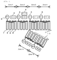
- FIG. 2 is a schematic diagram of a roller conveyer-type conveyance system in which zones are defined
- FIG. 3 is a block diagram illustrating a connection among the data processing slave station inside, a transmission system and a driving unit
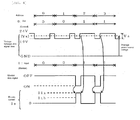
- FIG. 4 is a time chart of a transmission signal
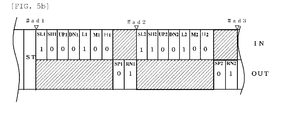
- FIGs. 5A to 5C are arrangements view illustrating transmission signals.
- a conveyance system 1 includes a plurality of conveyance units which include a motor driving roller and a plurality of interlocking rollers which interlock with the motor driving roller through a power transmission means. Also, a mediation station 2 which generates a start signal and an end signal of a transmission signal and a clock signal subsequent thereto, a plurality of data processing slave stations 3 which are connected to transmission lines DP and DN, a load sensor 4, a motor driver 5, and a driving motor 6 are provided.
- the data processing slave station 3 is connected to the common transmission lines DP and DN through a data processing slave station I/O unit 11, and is connected to a CPU 13 and a RAM 15 through an I/O bus 17 and a local bus 16 to exchange signal data. That is, the data processing slave station 3 obtains information about a predetermined station from monitor/control data about a plurality of stations of the data processing slave station 3 which is transmitted to the transmission lines DP and DN, and outputs information about an own station to the transmission lines DP and DN.
- the CPU 13 determines control/monitoring of an own station based on obtained information about a predetermined station through a control program stored in a ROM 14. Control contents are handled by the CPU 13 according to a control program stored in the ROM 14 as output data OUT of the RAM 15, and output to the motor driver 5 which will be described alter from a control output unit 20 through an I/O bus 18. The control contents are also output to the transmission lines DP and DN as information about an own station by the data processing slave station I/O unit 11 through the local bus 16 and the I/O bus 17.
- the CPU 13 obtains a monitor signal from the load sensor 4 connected to a sensor input 19 and outputs the monitor signal to the transmission lines DP and DN through the data processing slave station I/O unit 11.
- the sensor input unit 19 exchanges signal data with the CPU 13 and the RAM 15 through the I/O bus 18 and the local bus 16.
- the sensor input unit 19 also obtains speed data, an overload signal, a driver malfunction signal, and a motor malfunction signal of the motor driver 5 and outputs the speed data, the overload signal, the driver malfunction signal, and the motor malfunction signal to the transmission lines DP and DN as information about an own station like the monitor signal.
- the mediation station 2 generates a start signal and a clock signal subsequent thereto and outputs the start signal and the clock signal to the transmission lines DP and DN.
- the data processing slave station 3 counts the number of clocks to perceive which data value belongs to which data processing slave station. The transmission signal will be described in detail later.
- An address number is imparted to each of the plurality of data processing slave stations 3, and in an example of FIG. 1 , the data processing slave station 3 of an address number 1 (#ad1) is connected to the motor driver 5 of a zone 1.
- the data processing slave station 3 is connected to the load sensor 4 including a reflective-type sensor SL1, and obtains an input signal of the load sensor 4 and speed data, an overload signal, a driver malfunction signal, and a motor malfunction signal of the motor driver 5 from the sensor input unit 19 and outputs them to the transmission lines DP and DN as described above.
- a conveyance speed instruction signal of the zone 1 according to determination based on information of a different station is output from the control output unit 20 to the motor driver 5.
- the motor driver 5 sets a rotation speed of the driving motor 6 by an instruction signal from the control output unit 20 of the data processing slave station 3 and transfers a conveyed object on the zone 1 to the next zone 2.
- the data processing slave station 3 of the address number 2 (#ad2) is identical to that in the zone 1 in obtaining a monitor signal and outputting a control signal, but a load sensor 4 includes a reflective-type sensor SL2 which is identical to the sensor SL1 is provided and a reflective-type load height sensor SH2.
- the reflective-type load height sensor SH2 is a sensor which detects a conveyed object having a height equal to or more than a predetermined height.
- An input signal of the load sensor 4 which includes both a signal of the sensor SL2 and a signal of the sensor SH2 is output to the transmission lines DP and DN as in the data processing slave station 3 of the #ad1.
- a signal perceived in the load height sensor SH2, that is, a load height may be used as a control input for branching a conveyance direction of a load, performing a classification conveyance thereof or dividing/collecting loads.
- the data processing slave station 3 of an address number 1a (#ad1a) installed in a zone 1a of a path changing direction from a conveyance direction which is an advancing direction takes over a conveyed object from the zone 1 and operates the motor driver 5 which operates a transmission system of the zone 1a when a monitor signal of the load height sensor SH2 is reflected in control/monitor data and the information is obtained.
- FIG. 3 illustrates data stored in the data processing slave station 3 when a conveyed object with a high height (hereinafter, a "conveyed object H") is conveyed up to the zone 2.
- a conveyed object with a high height hereinafter, a "conveyed object H"
- IN denotes each zone status
- OUT denotes output information for the control output unit 20.
- "OUT" information is used to control whether to operate the whole system and does not control a detailed state of each zone.
- RN is "1" when an operation is possible
- SP is "1" when an operation is impossible.
- all RNs in "OUT” information are "1".
- Information indicated by a bold frame is information of an own station.
- the load height sensor SH2 does not detect a load, that is, when the conveyed object does not have a height equal to or more than a predetermined height
- the data processing slave station 3 of the address number 3 (#ad3) installed in a zone 3 in an advance direction obtains the information and operates a motor driver 5 of a driving motor M3 to continuously convey the conveyed object in an advance direction.
- SH1 and SH3 are input portions which are prepared for the same sensor signal even with respect to addresses which do not have a load height sensor, and so a load height sensor can be easily installed.
- a signal input portion corresponding to a load height sensor is "0".
- a first motor M1 is a driving motor 7 of the zone 1 and configures the zone 1 together with three interlocking rollers 8 which interlock with the driving motor 7. Ends of the interlocking rollers serve as pulleys for transmitting power through a belt, and the driving motor and the interlocking roller conveys a load on the rollers while transferring torque. Also, opposite ends of the interlocking rollers serve as pulleys for transmitting power through a belt, and transmit power to the subsequent interlocking rollers through a belt. Similarly, a second motor M2 configures the zone 2 together with a driving motor 7 of the zone 2 and three interlocking rollers 8.
- a third motor M3 and a fourth motor M4 form zones of an advancing direction and are in charge of conveyance of an advancing movement 9 direction.
- a load sensor SL2-1 in a zone of a branch direction 10 and a load sensor SL2-2 in a subsequent zone serve as detection sensors which detect a load status.
- a speed control signal is transmitted from the controlled unit 22 to the motor driver 5 to operate the driving motor 6.
- the motor driver transmits an error signal occurring when an overload occurs in the driving motor 6 or a malfunction occurs in a driver circuit to the sensor input unit 19.
- the information is transmitted to the transmission lines DP and DN, so that line control is performed when a malfunction or an error is detected.
- the load sensor 4 of #ad1 obtains a monitor signal from the sensor input unit 19, and stores monitor data in a monitor signal area of an address 1 of the RAM 15 through the I/O bus 18 under control of the CPU 13.
- the CPU 13 performs a logical operation of control output data stored in the RAM 17 using a program stored in the ROM 14 and then transmits a signal to the control output unit 20 through the local bus 16 and the I/O bus 18.
- the controlled unit 22 outputs a control signal for performing control for acceleration, deceleration, constant speed, stop, forward movement, or backward movement to the motor driver 5.
- the driving motor is a servomotor or an AC motor, and performs an operation of acceleration, deceleration, constant speed, stop, forward movement, or backward movement.
- a conveyance commonly means a transfer of an advancing direction, but, for example, in the case of outdoor conveyance facilities or in the case of loads which are required to maintain a cleaning level or a temperature under a certain condition, when a malfunction occurs in a process which is currently being performed, loads are moved back to a standby place by backward movement. Due to this operation, a low temperature, a cleaning level and humidity of loads can be maintained in a prescribed state.
- FIG. 4 is a time chart of a transmission signal of the conveyance control system 1.
- FIG. 4 illustrates a case in which data values of addresses 0 to 3 of a control/monitor data signal output from the mediation station 1 are "0101", and an input from the sensor unit 7 to which addresses 0 to 3 are "0011".
- the address is not an address imparted to the data processing slave station 3 but to indicate a position in a monitor/control data signal.
- a serial pulse voltage signal of this embodiment one cycle (t0) of a clock CK, that is, each address is divided into at least an input period (i) and an output period (o) subsequent thereto.
- a first 3/4 cycle which becomes a low level is an input period
- a final 1/4 cycle is an output period.
- a first 1/4 cycle which becomes a low level is an input period
- a final 3/4 cycle is an output period.
- a monitor data signal which includes a current signal Is is superimposed, and a mediation station input unit 18 extracts the superimposed monitor data signal.
- a mediation station output unit 15 obtains a monitor signal which is obtained during previous output as a control signal, and superimposes a control data signal onto a serial pulse voltage signal and outputs the superimposed signal to the transmission lines DP and DN during the output period.
- the control/monitor signal transmission system corresponds an input signal (a monitor signal form the sensor unit 7) and an output signal (a control signal for the motor driver 5 in a 1:1 correspondence method and transmits them as described above. Therefore, a simple configuration in which a control unit and a master station of a conventional art are omitted is realized, and the maintenance is easy, and the cost is low.
- an output signal including a pulse width modulation signal is controlled by an input signal including an electric current signal. Therefore, virtual two-way transmission (actually, as will be described later, a transmission moment is not bi-directional) of an input signal and an output signal can be performed, and a power line can be omitted.
- an in this example by using an electric current signal as a monitor signal, and a voltage signal which is modulated in pulse width as a control signal (a combination of a current modulation monitor signal and a pulse width modulation control signal), a transmission control system of high reliability can be realized in manufacturing factories under an unfavorable condition in which a voltage noise is large.
- electric power used by the data processing slave station 3 is supplied (Vcp and Vcg) through a power source unit 12 from the common transmission lines DP and DN.
- a method of superimposing electric power onto a transmission line is a wiring omission, so-called wiring saving technology and can reduce wiring.
- a control signal includes a pulse voltage of a power source voltage Vx, that is, 24V level and a pulse voltage of "a low level of high potential" which is a level smaller (in absolute value) than the power source voltage and larger (in absolute value) than a high level signal of a different circuit portion, that is, 19V level. Therefore, it is sufficiently larger than a CMOS high level signal 5V of a different circuit portion (for example, a CMOS logic circuit portion).
- an electric potential difference Vs of a clock CK that is, between a high level and a low level of a pulse voltage, is 5V
- a threshold value as an intermediate value thereof (21.5V when a DN signal line is used as a reference level)
- they can be sufficiently discriminated. That is, an electric potential difference Vs is equal to a CMOS logic amplitude of a different circuit portion (for example, a CMOS logic circuit portion). Therefore, a serial pulse voltage signal may be regarded as a signal obtained by level-shifting a clock of the electric potential difference Vs "as is" and modulating a pulse width thereof according to a control data signal.
- an average power source voltage realized by transmitted average power becomes too high, that is, +21.5V which is about a center value of a corresponding amplitude as indicated by a dashed line in FIG. 4 . Therefore, even though, for example, a power line P is omitted, power capacity enough for operating each of a plurality of data processing slave stations 3 can be transmitted.
- FIGs. 5A to 5C are arrangement views illustrating transmission signals of the conveyance control system 1.
- FIGs. 5A and 5B illustrate arrangements of transmission signals corresponding to the zones 1 and 2
- FIG. 5C illustrates an arrangement of transmission signals corresponding to the zones 1a and 1b.
- An upper portion of the drawing denotes an input IN which represents each zone status, and a lower portion thereof denotes an output signal OUT which controls whether to operate.
- OUT information is "1" in all RNs.
- Transmission signals illustrated in FIGs. 5A to 5C start from respective start signals ST, and input/output signals of from an address 1 (#ad1) to an address 1b (#ad1b) are continuing as one cycle.
- FIG. 5A illustrates a signal of a state in which the conveyed object H is in the zone 1
- FIGs. 5B and 5C illustrate signals of states in which the conveyed object H is transferred to the zone 2.
- the data processing slave station 3 of #ad1 conveys the conveyed object H by a low speed operation.
- the conveyed object H is not transferred to the zone 2 yet, and in an input signal of FIG. 5A , SL1 which represents a load sensor of #ad1 and L1 which represents a low speed are "1", and SL2 which represents a load sensor of #ad2 and SH2 are "0".
- L2 which represents a low speed becomes "1".
- a serial pulse voltage signal is divided into an input period and an output period subsequent thereto.
- an input period an input to the data processing station 3 is performed, and during an output period, an output from a mediation station 2 is performed, so that signal arrangements illustrated in FIGS. 5A to 5C are formed.
- a master station which has an operation processing function which is more advanced than a mediation station 2 may be used, and in this case, a signal arrangement accords with a transmission method of a master station.
- a mediation station 2 may have an input memory holding area for storing input data of the whole system and an output memory holding area for storing output data of the whole system according to a usage situation.
- Monitor data of a monitor signal output from the data processing slave station 3 is stored in the input memory retaining area.
- Stored data is written (stored by overwriting) in the output memory holding area for every one clock or in every one cycle (for each block) of transmission data.
- control of a conveyance system in which control between conveyance zones is smooth and energy is saved can be performed without a control delay by a processing delay of a central control unit such as a PLC.
- a system in which basic conveyance control can be easily performed without depending on a central control unit such as a PLC can be provided. Also, since a lot of wirings are not required between a sensor or an actuator and a control apparatus such as a PLC, wiring can be easily simplified. In addition, there are advantages that smooth acceleration and deceleration can be optimally controlled by appropriate determination control of each data processing slave station, an idling operation can be reduced, and control of easily realizing a smooth energy saving operation can be performed.
Landscapes
- Engineering & Computer Science (AREA)
- General Engineering & Computer Science (AREA)
- Manufacturing & Machinery (AREA)
- Quality & Reliability (AREA)
- Physics & Mathematics (AREA)
- General Physics & Mathematics (AREA)
- Automation & Control Theory (AREA)
- Programmable Controllers (AREA)
- Control Of Conveyors (AREA)
Applications Claiming Priority (1)
| Application Number | Priority Date | Filing Date | Title |
|---|---|---|---|
| JP2008220156A JP4979658B2 (ja) | 2008-08-28 | 2008-08-28 | 搬送制御システム及び搬送制御方法 |
Publications (3)
| Publication Number | Publication Date |
|---|---|
| EP2159655A2 true EP2159655A2 (de) | 2010-03-03 |
| EP2159655A3 EP2159655A3 (de) | 2011-01-19 |
| EP2159655B1 EP2159655B1 (de) | 2012-03-21 |
Family
ID=41479298
Family Applications (1)
| Application Number | Title | Priority Date | Filing Date |
|---|---|---|---|
| EP09166464A Active EP2159655B1 (de) | 2008-08-28 | 2009-07-27 | Fördersteuerungssystem und Fördersteuerungsverfahren |
Country Status (5)
| Country | Link |
|---|---|
| US (1) | US8396587B2 (de) |
| EP (1) | EP2159655B1 (de) |
| JP (1) | JP4979658B2 (de) |
| KR (1) | KR101215430B1 (de) |
| AT (1) | ATE550700T1 (de) |
Cited By (6)
| Publication number | Priority date | Publication date | Assignee | Title |
|---|---|---|---|---|
| CH707879A1 (de) * | 2013-04-11 | 2014-10-15 | Ferag Ag | Regelung von Antrieben von Förderabschnitten eines Fördersystems. |
| EP2829496A4 (de) * | 2012-03-19 | 2016-01-06 | Itoh Denki Co Ltd | Zonensteuerung und fördervorrichtung |
| EP3441832A1 (de) * | 2017-08-07 | 2019-02-13 | Wieland Electric GmbH | Modulare speicherprogrammierbare steuerung |
| CN111830893A (zh) * | 2019-12-03 | 2020-10-27 | 上海稳擎科技有限公司 | 一种设备运维监控系统 |
| CN112707112A (zh) * | 2019-10-25 | 2021-04-27 | 伊东电机株式会社 | 输送系统 |
| US12275599B2 (en) | 2019-04-05 | 2025-04-15 | Itoh Denki Co., Ltd. | Conveyor system, cause information report device, and computer-readable recording medium recording program for cause information report device |
Families Citing this family (11)
| Publication number | Priority date | Publication date | Assignee | Title |
|---|---|---|---|---|
| US8887897B2 (en) * | 2010-08-31 | 2014-11-18 | Itoh Denki Co., Ltd. | Fault diagnosis method for roller conveyor, roller conveyor, and controller for conveyor |
| JP5879520B2 (ja) * | 2011-11-07 | 2016-03-08 | パナソニックIpマネジメント株式会社 | 通信システムおよびそれに用いる伝送ユニット |
| US20150005927A1 (en) * | 2012-02-10 | 2015-01-01 | Cassidian Airborne Solutions Gmbh | Flexible, scalable freight loading system |
| JP5882810B2 (ja) * | 2012-03-29 | 2016-03-09 | 伊東電機株式会社 | 搬送装置、並びに、物品保管装置 |
| US10322883B2 (en) * | 2014-11-18 | 2019-06-18 | Itoh Denki Co. | Conveyor device, conveyor system, zone controller, CAD device, and method for manufacturing conveyor device |
| JP6355854B2 (ja) * | 2015-08-28 | 2018-07-11 | 株式会社 エニイワイヤ | 搬送システム |
| WO2017061088A1 (ja) * | 2015-10-08 | 2017-04-13 | ソニー株式会社 | サーボモータ、サーボモータシステムおよび電力供給方法 |
| KR20210051688A (ko) * | 2019-10-31 | 2021-05-10 | 세메스 주식회사 | 대상물 이송 장치 및 그 제어 방법 |
| CN111942861B (zh) * | 2020-08-31 | 2025-05-30 | 深圳顺丰泰森控股(集团)有限公司 | 传输装置及分拣设备 |
| US11597604B1 (en) * | 2022-03-02 | 2023-03-07 | Jakob Simon | Conveyor safely guard modules |
| CN115744146A (zh) * | 2022-11-15 | 2023-03-07 | 湘潭大学 | 一种新型智能输料控制系统 |
Citations (2)
| Publication number | Priority date | Publication date | Assignee | Title |
|---|---|---|---|---|
| JP2003292141A (ja) | 2002-03-29 | 2003-10-15 | Kito Corp | 荷搬送設備の荷搬送条件設定方法 |
| JP2005047705A (ja) | 2003-07-31 | 2005-02-24 | Daifuku Logistic Technology:Kk | 搬送物のセンタリング装置 |
Family Cites Families (18)
| Publication number | Priority date | Publication date | Assignee | Title |
|---|---|---|---|---|
| JPS6196390A (ja) * | 1984-10-18 | 1986-05-15 | 株式会社 タクマ | ロ−ラキルン |
| JPH07172549A (ja) * | 1993-12-17 | 1995-07-11 | Daifuku Co Ltd | コンベヤ装置 |
| JPH08143133A (ja) * | 1994-11-17 | 1996-06-04 | Toyo Kanetsu Kk | 移送装置制御方法および移送装置 |
| JP3458026B2 (ja) * | 1995-09-14 | 2003-10-20 | Nke株式会社 | 制御・監視システム |
| JP3374738B2 (ja) * | 1998-01-07 | 2003-02-10 | 株式会社ダイフク | コンベヤ装置 |
| JP2001106331A (ja) * | 1999-10-08 | 2001-04-17 | Kyowa Seisakusho:Kk | 搬送制御システム |
| US6701214B1 (en) * | 2000-04-27 | 2004-03-02 | Rockwell Automation Technologies, Inc. | Driver board control system for modular conveyer with address-based network for inter-conveyor communication |
| AU2001222539A1 (en) * | 2000-04-27 | 2001-11-12 | Rockwell Technologies, Llc | Driver board control system for modular conveyor with address-based network for inter-conveyor communication |
| US6574515B1 (en) * | 2000-05-12 | 2003-06-03 | Rosemount Inc. | Two-wire field-mounted process device |
| JP2002012315A (ja) * | 2000-06-30 | 2002-01-15 | Algo System:Kk | コンベアシステム |
| EP1433726B1 (de) * | 2001-06-20 | 2007-07-25 | Itoh Electric Company Limited | Zonensteuerung |
| US6827202B2 (en) * | 2001-12-21 | 2004-12-07 | Balluff, Inc. | Methods and apparatus for controlling conveyor zones |
| JP3795392B2 (ja) | 2001-12-28 | 2006-07-12 | 株式会社 エニイワイヤ | 制御・監視信号伝送システム |
| US7167527B1 (en) * | 2002-05-02 | 2007-01-23 | Integrated Memory Logic, Inc. | System and method for multi-symbol interfacing |
| JP4322071B2 (ja) * | 2003-09-04 | 2009-08-26 | 株式会社 エニイワイヤ | 制御・監視信号伝送システム |
| KR101165941B1 (ko) | 2005-11-14 | 2012-07-18 | 애니와이어 가부시키가이샤 | 제어/감시 신호 전송 시스템 |
| JP4808118B2 (ja) * | 2006-08-25 | 2011-11-02 | 株式会社 エニイワイヤ | 入出力ターミナル |
| US8050795B2 (en) * | 2007-03-20 | 2011-11-01 | Donald L. Dollens | Conveyor drive control system |
-
2008
- 2008-08-28 JP JP2008220156A patent/JP4979658B2/ja active Active
-
2009
- 2009-07-27 EP EP09166464A patent/EP2159655B1/de active Active
- 2009-07-27 AT AT09166464T patent/ATE550700T1/de active
- 2009-07-31 US US12/533,177 patent/US8396587B2/en not_active Expired - Fee Related
- 2009-08-27 KR KR1020090079649A patent/KR101215430B1/ko active Active
Patent Citations (2)
| Publication number | Priority date | Publication date | Assignee | Title |
|---|---|---|---|---|
| JP2003292141A (ja) | 2002-03-29 | 2003-10-15 | Kito Corp | 荷搬送設備の荷搬送条件設定方法 |
| JP2005047705A (ja) | 2003-07-31 | 2005-02-24 | Daifuku Logistic Technology:Kk | 搬送物のセンタリング装置 |
Cited By (13)
| Publication number | Priority date | Publication date | Assignee | Title |
|---|---|---|---|---|
| EP2829496A4 (de) * | 2012-03-19 | 2016-01-06 | Itoh Denki Co Ltd | Zonensteuerung und fördervorrichtung |
| US9446907B2 (en) | 2012-03-19 | 2016-09-20 | Itoh Denki Co., Ltd. | Zone controller and conveyor device |
| CH707879A1 (de) * | 2013-04-11 | 2014-10-15 | Ferag Ag | Regelung von Antrieben von Förderabschnitten eines Fördersystems. |
| WO2014166004A1 (de) | 2013-04-11 | 2014-10-16 | Ferag Ag | Fördersystem mit einer regelungseinheit und entsprechendes verfahren |
| US9714143B2 (en) | 2013-04-11 | 2017-07-25 | Ferag Ag | Regulation of drives of conveying sections of a conveying system |
| AU2014252685B2 (en) * | 2013-04-11 | 2017-08-17 | Ferag Ag | Conveyor system with a regulating unit, and corresponding method |
| EP3441832A1 (de) * | 2017-08-07 | 2019-02-13 | Wieland Electric GmbH | Modulare speicherprogrammierbare steuerung |
| US12275599B2 (en) | 2019-04-05 | 2025-04-15 | Itoh Denki Co., Ltd. | Conveyor system, cause information report device, and computer-readable recording medium recording program for cause information report device |
| CN112707112A (zh) * | 2019-10-25 | 2021-04-27 | 伊东电机株式会社 | 输送系统 |
| EP3812861A1 (de) * | 2019-10-25 | 2021-04-28 | Itoh Denki Co., Ltd. | Fördersystem |
| CN112707112B (zh) * | 2019-10-25 | 2024-05-17 | 伊东电机株式会社 | 输送系统 |
| US12578697B2 (en) | 2019-10-25 | 2026-03-17 | Itoh Denki Co., Ltd. | Conveyor system |
| CN111830893A (zh) * | 2019-12-03 | 2020-10-27 | 上海稳擎科技有限公司 | 一种设备运维监控系统 |
Also Published As
| Publication number | Publication date |
|---|---|
| EP2159655B1 (de) | 2012-03-21 |
| EP2159655A3 (de) | 2011-01-19 |
| ATE550700T1 (de) | 2012-04-15 |
| JP4979658B2 (ja) | 2012-07-18 |
| US8396587B2 (en) | 2013-03-12 |
| KR20100027021A (ko) | 2010-03-10 |
| KR101215430B1 (ko) | 2012-12-26 |
| US20100058098A1 (en) | 2010-03-04 |
| JP2010052900A (ja) | 2010-03-11 |
Similar Documents
| Publication | Publication Date | Title |
|---|---|---|
| EP2159655B1 (de) | Fördersteuerungssystem und Fördersteuerungsverfahren | |
| EP1277096B1 (de) | Treiber-steuerungssystem für modulare förderbänder mit address-basiertem netzwerk | |
| US6898483B2 (en) | Driver board control system for modular conveyor with address-based network for inter-conveyer communication | |
| US9643232B2 (en) | Servo press line operation method and servo press line operation control device | |
| CN111056259A (zh) | 滚床减速检测传感器失效预判方法、系统及存储介质 | |
| EP3764729A1 (de) | Drahtloskommunikationssystem, drahtlose slave-vorrichtung und drahtlose master-vorrichtung | |
| CN115786631B (zh) | 适用于转炉倾动零速悬停的控制方法及系统、设备、介质 | |
| US8183809B2 (en) | Drive device for at least one electric motor and drive control unit interacting with the drive device | |
| US6950726B2 (en) | Method and device for numerical control return to origin of a master and slave shaft | |
| US9694986B2 (en) | Transport device and transport method for transporting a fragile object | |
| CN208482831U (zh) | 自适应差速剔废系统 | |
| KR101081935B1 (ko) | 복수의 채널 네트워크에 기반한 다축 모션 제어 장치 및 방법 | |
| US20210171286A1 (en) | Analog-controlled transport device with data read-out | |
| JPH0632883B2 (ja) | 物品の製造管理方法 | |
| US12155328B2 (en) | Multi-axis servo control system | |
| EP4336290A1 (de) | System und verfahren zur dynamischen nest- und routing-einstellung | |
| CN117155175A (zh) | 一种蜗杆伺服控制方法、系统、装置及存储介质 | |
| CN111039557B (zh) | 一种传动系统及其控制方法 | |
| KR890002515B1 (ko) | 자동 가공라인에 있어서의 선재절단기와 자동가공 시스템과의 동기(同期)방법 및 장치 | |
| CN115799138B (zh) | 控制半导体晶圆在传输装置上定位停止的方法 | |
| KR20160022722A (ko) | 협업 로봇의 동기화 장치 및 동기화 방법 | |
| JP4956090B2 (ja) | 制御情報伝送システム | |
| JP7746890B2 (ja) | サーボシステム | |
| CN121791057A (zh) | 电机同步控制方法、系统及装置 | |
| US20220156010A1 (en) | Method for Communicating with one or More Field Devices |
Legal Events
| Date | Code | Title | Description |
|---|---|---|---|
| PUAI | Public reference made under article 153(3) epc to a published international application that has entered the european phase |
Free format text: ORIGINAL CODE: 0009012 |
|
| AK | Designated contracting states |
Kind code of ref document: A2 Designated state(s): AT BE BG CH CY CZ DE DK EE ES FI FR GB GR HR HU IE IS IT LI LT LU LV MC MK MT NL NO PL PT RO SE SI SK SM TR |
|
| AX | Request for extension of the european patent |
Extension state: AL BA RS |
|
| PUAL | Search report despatched |
Free format text: ORIGINAL CODE: 0009013 |
|
| AK | Designated contracting states |
Kind code of ref document: A3 Designated state(s): AT BE BG CH CY CZ DE DK EE ES FI FR GB GR HR HU IE IS IT LI LT LU LV MC MK MT NL NO PL PT RO SE SI SK SM TR |
|
| AX | Request for extension of the european patent |
Extension state: AL BA RS |
|
| 17P | Request for examination filed |
Effective date: 20110715 |
|
| GRAP | Despatch of communication of intention to grant a patent |
Free format text: ORIGINAL CODE: EPIDOSNIGR1 |
|
| GRAS | Grant fee paid |
Free format text: ORIGINAL CODE: EPIDOSNIGR3 |
|
| GRAA | (expected) grant |
Free format text: ORIGINAL CODE: 0009210 |
|
| AK | Designated contracting states |
Kind code of ref document: B1 Designated state(s): AT BE BG CH CY CZ DE DK EE ES FI FR GB GR HR HU IE IS IT LI LT LU LV MC MK MT NL NO PL PT RO SE SI SK SM TR |
|
| REG | Reference to a national code |
Ref country code: GB Ref legal event code: FG4D |
|
| REG | Reference to a national code |
Ref country code: CH Ref legal event code: EP |
|
| REG | Reference to a national code |
Ref country code: IE Ref legal event code: FG4D |
|
| REG | Reference to a national code |
Ref country code: AT Ref legal event code: REF Ref document number: 550700 Country of ref document: AT Kind code of ref document: T Effective date: 20120415 |
|
| REG | Reference to a national code |
Ref country code: DE Ref legal event code: R096 Ref document number: 602009005974 Country of ref document: DE Effective date: 20120516 |
|
| REG | Reference to a national code |
Ref country code: NL Ref legal event code: VDEP Effective date: 20120321 |
|
| PG25 | Lapsed in a contracting state [announced via postgrant information from national office to epo] |
Ref country code: NO Free format text: LAPSE BECAUSE OF FAILURE TO SUBMIT A TRANSLATION OF THE DESCRIPTION OR TO PAY THE FEE WITHIN THE PRESCRIBED TIME-LIMIT Effective date: 20120621 Ref country code: HR Free format text: LAPSE BECAUSE OF FAILURE TO SUBMIT A TRANSLATION OF THE DESCRIPTION OR TO PAY THE FEE WITHIN THE PRESCRIBED TIME-LIMIT Effective date: 20120321 Ref country code: LT Free format text: LAPSE BECAUSE OF FAILURE TO SUBMIT A TRANSLATION OF THE DESCRIPTION OR TO PAY THE FEE WITHIN THE PRESCRIBED TIME-LIMIT Effective date: 20120321 |
|
| LTIE | Lt: invalidation of european patent or patent extension |
Effective date: 20120321 |
|
| PG25 | Lapsed in a contracting state [announced via postgrant information from national office to epo] |
Ref country code: LV Free format text: LAPSE BECAUSE OF FAILURE TO SUBMIT A TRANSLATION OF THE DESCRIPTION OR TO PAY THE FEE WITHIN THE PRESCRIBED TIME-LIMIT Effective date: 20120321 Ref country code: GR Free format text: LAPSE BECAUSE OF FAILURE TO SUBMIT A TRANSLATION OF THE DESCRIPTION OR TO PAY THE FEE WITHIN THE PRESCRIBED TIME-LIMIT Effective date: 20120622 Ref country code: FI Free format text: LAPSE BECAUSE OF FAILURE TO SUBMIT A TRANSLATION OF THE DESCRIPTION OR TO PAY THE FEE WITHIN THE PRESCRIBED TIME-LIMIT Effective date: 20120321 |
|
| REG | Reference to a national code |
Ref country code: AT Ref legal event code: MK05 Ref document number: 550700 Country of ref document: AT Kind code of ref document: T Effective date: 20120321 |
|
| PG25 | Lapsed in a contracting state [announced via postgrant information from national office to epo] |
Ref country code: CY Free format text: LAPSE BECAUSE OF FAILURE TO SUBMIT A TRANSLATION OF THE DESCRIPTION OR TO PAY THE FEE WITHIN THE PRESCRIBED TIME-LIMIT Effective date: 20120321 |
|
| PG25 | Lapsed in a contracting state [announced via postgrant information from national office to epo] |
Ref country code: PL Free format text: LAPSE BECAUSE OF FAILURE TO SUBMIT A TRANSLATION OF THE DESCRIPTION OR TO PAY THE FEE WITHIN THE PRESCRIBED TIME-LIMIT Effective date: 20120321 Ref country code: IS Free format text: LAPSE BECAUSE OF FAILURE TO SUBMIT A TRANSLATION OF THE DESCRIPTION OR TO PAY THE FEE WITHIN THE PRESCRIBED TIME-LIMIT Effective date: 20120721 Ref country code: CZ Free format text: LAPSE BECAUSE OF FAILURE TO SUBMIT A TRANSLATION OF THE DESCRIPTION OR TO PAY THE FEE WITHIN THE PRESCRIBED TIME-LIMIT Effective date: 20120321 Ref country code: RO Free format text: LAPSE BECAUSE OF FAILURE TO SUBMIT A TRANSLATION OF THE DESCRIPTION OR TO PAY THE FEE WITHIN THE PRESCRIBED TIME-LIMIT Effective date: 20120321 Ref country code: EE Free format text: LAPSE BECAUSE OF FAILURE TO SUBMIT A TRANSLATION OF THE DESCRIPTION OR TO PAY THE FEE WITHIN THE PRESCRIBED TIME-LIMIT Effective date: 20120321 Ref country code: BE Free format text: LAPSE BECAUSE OF FAILURE TO SUBMIT A TRANSLATION OF THE DESCRIPTION OR TO PAY THE FEE WITHIN THE PRESCRIBED TIME-LIMIT Effective date: 20120321 Ref country code: SE Free format text: LAPSE BECAUSE OF FAILURE TO SUBMIT A TRANSLATION OF THE DESCRIPTION OR TO PAY THE FEE WITHIN THE PRESCRIBED TIME-LIMIT Effective date: 20120321 Ref country code: SI Free format text: LAPSE BECAUSE OF FAILURE TO SUBMIT A TRANSLATION OF THE DESCRIPTION OR TO PAY THE FEE WITHIN THE PRESCRIBED TIME-LIMIT Effective date: 20120321 |
|
| PG25 | Lapsed in a contracting state [announced via postgrant information from national office to epo] |
Ref country code: PT Free format text: LAPSE BECAUSE OF FAILURE TO SUBMIT A TRANSLATION OF THE DESCRIPTION OR TO PAY THE FEE WITHIN THE PRESCRIBED TIME-LIMIT Effective date: 20120723 Ref country code: SK Free format text: LAPSE BECAUSE OF FAILURE TO SUBMIT A TRANSLATION OF THE DESCRIPTION OR TO PAY THE FEE WITHIN THE PRESCRIBED TIME-LIMIT Effective date: 20120321 |
|
| PLBE | No opposition filed within time limit |
Free format text: ORIGINAL CODE: 0009261 |
|
| STAA | Information on the status of an ep patent application or granted ep patent |
Free format text: STATUS: NO OPPOSITION FILED WITHIN TIME LIMIT |
|
| PG25 | Lapsed in a contracting state [announced via postgrant information from national office to epo] |
Ref country code: AT Free format text: LAPSE BECAUSE OF FAILURE TO SUBMIT A TRANSLATION OF THE DESCRIPTION OR TO PAY THE FEE WITHIN THE PRESCRIBED TIME-LIMIT Effective date: 20120321 Ref country code: DK Free format text: LAPSE BECAUSE OF FAILURE TO SUBMIT A TRANSLATION OF THE DESCRIPTION OR TO PAY THE FEE WITHIN THE PRESCRIBED TIME-LIMIT Effective date: 20120321 Ref country code: NL Free format text: LAPSE BECAUSE OF FAILURE TO SUBMIT A TRANSLATION OF THE DESCRIPTION OR TO PAY THE FEE WITHIN THE PRESCRIBED TIME-LIMIT Effective date: 20120321 |
|
| 26N | No opposition filed |
Effective date: 20130102 |
|
| PG25 | Lapsed in a contracting state [announced via postgrant information from national office to epo] |
Ref country code: IT Free format text: LAPSE BECAUSE OF FAILURE TO SUBMIT A TRANSLATION OF THE DESCRIPTION OR TO PAY THE FEE WITHIN THE PRESCRIBED TIME-LIMIT Effective date: 20120321 Ref country code: MC Free format text: LAPSE BECAUSE OF NON-PAYMENT OF DUE FEES Effective date: 20120731 Ref country code: MK Free format text: LAPSE BECAUSE OF FAILURE TO SUBMIT A TRANSLATION OF THE DESCRIPTION OR TO PAY THE FEE WITHIN THE PRESCRIBED TIME-LIMIT Effective date: 20120321 |
|
| REG | Reference to a national code |
Ref country code: DE Ref legal event code: R097 Ref document number: 602009005974 Country of ref document: DE Effective date: 20130102 |
|
| REG | Reference to a national code |
Ref country code: FR Ref legal event code: ST Effective date: 20130329 |
|
| PG25 | Lapsed in a contracting state [announced via postgrant information from national office to epo] |
Ref country code: FR Free format text: LAPSE BECAUSE OF NON-PAYMENT OF DUE FEES Effective date: 20120731 Ref country code: ES Free format text: LAPSE BECAUSE OF FAILURE TO SUBMIT A TRANSLATION OF THE DESCRIPTION OR TO PAY THE FEE WITHIN THE PRESCRIBED TIME-LIMIT Effective date: 20120702 |
|
| REG | Reference to a national code |
Ref country code: IE Ref legal event code: MM4A |
|
| PG25 | Lapsed in a contracting state [announced via postgrant information from national office to epo] |
Ref country code: MT Free format text: LAPSE BECAUSE OF FAILURE TO SUBMIT A TRANSLATION OF THE DESCRIPTION OR TO PAY THE FEE WITHIN THE PRESCRIBED TIME-LIMIT Effective date: 20120321 Ref country code: BG Free format text: LAPSE BECAUSE OF FAILURE TO SUBMIT A TRANSLATION OF THE DESCRIPTION OR TO PAY THE FEE WITHIN THE PRESCRIBED TIME-LIMIT Effective date: 20120621 Ref country code: IE Free format text: LAPSE BECAUSE OF NON-PAYMENT OF DUE FEES Effective date: 20120727 |
|
| REG | Reference to a national code |
Ref country code: CH Ref legal event code: PL |
|
| GBPC | Gb: european patent ceased through non-payment of renewal fee |
Effective date: 20130727 |
|
| PG25 | Lapsed in a contracting state [announced via postgrant information from national office to epo] |
Ref country code: TR Free format text: LAPSE BECAUSE OF FAILURE TO SUBMIT A TRANSLATION OF THE DESCRIPTION OR TO PAY THE FEE WITHIN THE PRESCRIBED TIME-LIMIT Effective date: 20120321 Ref country code: CH Free format text: LAPSE BECAUSE OF NON-PAYMENT OF DUE FEES Effective date: 20130731 Ref country code: LI Free format text: LAPSE BECAUSE OF NON-PAYMENT OF DUE FEES Effective date: 20130731 Ref country code: GB Free format text: LAPSE BECAUSE OF NON-PAYMENT OF DUE FEES Effective date: 20130727 |
|
| PG25 | Lapsed in a contracting state [announced via postgrant information from national office to epo] |
Ref country code: SM Free format text: LAPSE BECAUSE OF FAILURE TO SUBMIT A TRANSLATION OF THE DESCRIPTION OR TO PAY THE FEE WITHIN THE PRESCRIBED TIME-LIMIT Effective date: 20120321 Ref country code: LU Free format text: LAPSE BECAUSE OF NON-PAYMENT OF DUE FEES Effective date: 20120727 |
|
| PG25 | Lapsed in a contracting state [announced via postgrant information from national office to epo] |
Ref country code: HU Free format text: LAPSE BECAUSE OF FAILURE TO SUBMIT A TRANSLATION OF THE DESCRIPTION OR TO PAY THE FEE WITHIN THE PRESCRIBED TIME-LIMIT Effective date: 20090727 |
|
| PGFP | Annual fee paid to national office [announced via postgrant information from national office to epo] |
Ref country code: DE Payment date: 20250722 Year of fee payment: 17 |