EP2159657A1 - Verfahren und Steuersystem zur Synchronisation eines Roboters und eines Förderbandes - Google Patents
Verfahren und Steuersystem zur Synchronisation eines Roboters und eines Förderbandes Download PDFInfo
- Publication number
- EP2159657A1 EP2159657A1 EP08162897A EP08162897A EP2159657A1 EP 2159657 A1 EP2159657 A1 EP 2159657A1 EP 08162897 A EP08162897 A EP 08162897A EP 08162897 A EP08162897 A EP 08162897A EP 2159657 A1 EP2159657 A1 EP 2159657A1
- Authority
- EP
- European Patent Office
- Prior art keywords
- robot
- conveyor
- control program
- waiting position
- speed
- Prior art date
- Legal status (The legal status is an assumption and is not a legal conclusion. Google has not performed a legal analysis and makes no representation as to the accuracy of the status listed.)
- Granted
Links
Images




Classifications
-
- G—PHYSICS
- G05—CONTROLLING; REGULATING
- G05B—CONTROL OR REGULATING SYSTEMS IN GENERAL; FUNCTIONAL ELEMENTS OF SUCH SYSTEMS; MONITORING OR TESTING ARRANGEMENTS FOR SUCH SYSTEMS OR ELEMENTS
- G05B19/00—Program-control systems
- G05B19/02—Program-control systems electric
- G05B19/418—Total factory control, i.e. centrally controlling a plurality of machines, e.g. direct or distributed numerical control [DNC], flexible manufacturing systems [FMS], integrated manufacturing systems [IMS] or computer integrated manufacturing [CIM]
- G05B19/41815—Total factory control, i.e. centrally controlling a plurality of machines, e.g. direct or distributed numerical control [DNC], flexible manufacturing systems [FMS], integrated manufacturing systems [IMS] or computer integrated manufacturing [CIM] characterised by the cooperation between machine tools, manipulators and conveyor or other workpiece supply system, workcell
- G05B19/4182—Total factory control, i.e. centrally controlling a plurality of machines, e.g. direct or distributed numerical control [DNC], flexible manufacturing systems [FMS], integrated manufacturing systems [IMS] or computer integrated manufacturing [CIM] characterised by the cooperation between machine tools, manipulators and conveyor or other workpiece supply system, workcell manipulators and conveyor only
-
- B—PERFORMING OPERATIONS; TRANSPORTING
- B25—HAND TOOLS; PORTABLE POWER-DRIVEN TOOLS; MANIPULATORS
- B25J—MANIPULATORS; CHAMBERS PROVIDED WITH MANIPULATION DEVICES
- B25J9/00—Program-controlled manipulators
- B25J9/0093—Program-controlled manipulators co-operating with conveyor means
-
- B—PERFORMING OPERATIONS; TRANSPORTING
- B05—SPRAYING OR ATOMISING IN GENERAL; APPLYING FLUENT MATERIALS TO SURFACES, IN GENERAL
- B05B—SPRAYING APPARATUS; ATOMISING APPARATUS; NOZZLES
- B05B13/00—Machines or plants for applying liquids or other fluent materials to surfaces of objects or other work by spraying, not covered by groups B05B1/00 - B05B11/00
- B05B13/02—Means for supporting work; Arrangement or mounting of spray heads; Adaptation or arrangement of means for feeding work
- B05B13/04—Means for supporting work; Arrangement or mounting of spray heads; Adaptation or arrangement of means for feeding work the spray heads being moved during spraying operation
- B05B13/0431—Means for supporting work; Arrangement or mounting of spray heads; Adaptation or arrangement of means for feeding work the spray heads being moved during spraying operation with spray heads moved by robots or articulated arms, e.g. for applying liquid or other fluent material to three-dimensional [3D] surfaces
-
- G—PHYSICS
- G05—CONTROLLING; REGULATING
- G05B—CONTROL OR REGULATING SYSTEMS IN GENERAL; FUNCTIONAL ELEMENTS OF SUCH SYSTEMS; MONITORING OR TESTING ARRANGEMENTS FOR SUCH SYSTEMS OR ELEMENTS
- G05B2219/00—Program-control systems
- G05B2219/30—Nc systems
- G05B2219/39—Robotics, robotics to robotics hand
- G05B2219/39102—Manipulator cooperating with conveyor
-
- G—PHYSICS
- G05—CONTROLLING; REGULATING
- G05B—CONTROL OR REGULATING SYSTEMS IN GENERAL; FUNCTIONAL ELEMENTS OF SUCH SYSTEMS; MONITORING OR TESTING ARRANGEMENTS FOR SUCH SYSTEMS OR ELEMENTS
- G05B2219/00—Program-control systems
- G05B2219/30—Nc systems
- G05B2219/45—Nc applications
- G05B2219/45013—Spraying, coating, painting
-
- G—PHYSICS
- G05—CONTROLLING; REGULATING
- G05B—CONTROL OR REGULATING SYSTEMS IN GENERAL; FUNCTIONAL ELEMENTS OF SUCH SYSTEMS; MONITORING OR TESTING ARRANGEMENTS FOR SUCH SYSTEMS OR ELEMENTS
- G05B2219/00—Program-control systems
- G05B2219/30—Nc systems
- G05B2219/45—Nc applications
- G05B2219/45065—Sealing, painting robot
-
- Y—GENERAL TAGGING OF NEW TECHNOLOGICAL DEVELOPMENTS; GENERAL TAGGING OF CROSS-SECTIONAL TECHNOLOGIES SPANNING OVER SEVERAL SECTIONS OF THE IPC; TECHNICAL SUBJECTS COVERED BY FORMER USPC CROSS-REFERENCE ART COLLECTIONS [XRACs] AND DIGESTS
- Y02—TECHNOLOGIES OR APPLICATIONS FOR MITIGATION OR ADAPTATION AGAINST CLIMATE CHANGE
- Y02P—CLIMATE CHANGE MITIGATION TECHNOLOGIES IN THE PRODUCTION OR PROCESSING OF GOODS
- Y02P90/00—Enabling technologies with a potential contribution to greenhouse gas [GHG] emissions mitigation
- Y02P90/02—Total factory control, e.g. smart factories, flexible manufacturing systems [FMS] or integrated manufacturing systems [IMS]
Definitions
- the present invention relates generally to industrial robots, and more particularly to synchronisation of industrial robots and conveyors, particularly when stoppages occur.
- Industrial robots are often used in production when repetitive movements are to be performed quickly and/or accurately.
- robots can be used for spray painting, welding, assembling, pick and place operations, etc.
- industrial robots are often used in conjunction with conveyors. The conveyor then moves the work object along a path, while at the same time, the industrial robot performs tasks related to the work object.
- the robot typically keeps a coordinate system synchronised with the position of the work object, the stoppage can result in the robot not being able to reach a desired part of the work object, which would have been in reach if the conveyor would have kept on moving. This type of problem is known as a kinematic limitation. Consequently, the programmed tasks can not be performed as planned.
- Another attempt at relieving the issued with kinematic limitation is to use halt the program in next point if the conveyor stops and a paint applicator is off. If the paint applicator is on, the program will halt in next point where paint is switched off. Thus, the paint result will be preserved, even if the conveyor has a stop. When the conveyor starts again, the robot program will continue.
- This feature has the limitation that it will test for the condition mentioned above only at points in the program where the paint is off. Consequently, if the paint applicator happens to be on at each of these points throughout the path, the robot will keep on spraying without halting the program, which would then result in a significant risk of kinematic limitation during long periods of paint application.
- WO 2005/063454 discloses a method of controlling a robot that is used in concert with at least one other robot to perform an operation on one or more work objects. If a stoppage occurs ahead of a task that a robot is carrying out, the robot completes the present task but does not proceed to the next task. Since the robot only can wait at the end of a task, the robot may have to continue for significant amount of time before it reaches such a point. This may result in discrepancies between the expected position of the work object and the actual position of the work object on the stopped conveyor. The same problems with kinematic limitations discussed above related to stoppages may thus still occur with the method described in WO 2005/063454 .
- An object of the present invention is to improve control of robots when conveyor stoppages occur.
- a method for controlling a robot performing movements according to a control program comprises the steps of: determining that a speed of a conveyor for moving a work object for the robot has deviated from a nominal speed; as a response to the determining that the speed of the conveyor has deviated, creating a new waiting position in the control program; effecting the waiting position for the robot; and resuming the control program such that the control program continues when the work object is in a position corresponding to the new waiting position.
- the waiting position By dynamically creating the waiting position, it can be created at a position which may be sooner than a pre-programmed waiting position, reducing any disadvantages of the stoppage. Moreover, no waiting positions need to be pre-programmed, which reduces the risk of any mistakes and also reduces the time to prepare for production.
- the dynamically generation of waiting positions also allows for faster changeovers between different work objects, as the waiting positions do not need to be taught in a teaching run.
- the step of effecting the waiting position may involve making the robot stationary.
- the step of creating a new waiting position may involve creating a plurality of waiting positions, and the step of effecting the waiting position involves effecting movement of the robot between the waiting positions.
- the determining that the speed of the conveyor has deviated from a nominal speed may involve determining that the conveyor has stopped.
- the step of effecting the waiting position may include effecting movements of the robot such that a predetermined part of the robot is in a position corresponding to the waiting position, and the step of resuming the control program may include effecting movements of the robot such that the predetermined part of the robot is in same position as prior to the step of effecting the waiting position.
- the step of suspending movement may include effecting movements of the robot such that a predetermined part of the robot is in a position corresponding to the waiting position, and the step of resuming the control program may include effecting movements of the robot such that the predetermined part of the robot is in same position as prior to the step of suspending.
- the method may further comprise, after the step of determining and before the step of resuming, the step of: suspending paint spraying performed by the robot on the work object.
- the resuming the control program may involve resuming the paint spraying.
- the suspending and resuming the paint spraying may be performed when a paint applicator of the robot has reached some distance from the work object. This allows for a smooth transition from spraying paint to stopping the spraying, and similarly, a smooth transition when the paint spraying is resumed. This solves the problem which may arise if the paint spraying is stopped or resumed abruptly, resulting in undesired, and visible and/or tactile artefacts from the suspended painting.
- the method may further comprise the steps of: as a response to the determining that the speed of the conveyor has deviated from the nominal speed, creating a virtual surface; as a response to a predetermined part of the robot passing the virtual surface in a first direction, suspending paint spraying; and as a response to the predetermined part of the robot passing the virtual surface in a second direction, the second direction being opposite to the first direction, resuming the paint spraying.
- the determining that the speed of the conveyor has deviated involves determining that an accumulated lag time of the conveyor exceeds a threshold lag time.
- a second aspect of the invention is a control system for a robot, the control system comprising a controller, wherein: the controller is configured to determine that a speed of a conveyor for moving a work object for the robot has deviated from a nominal speed; the controller is configured to, as a response to the determining that the speed of the conveyor has deviated, create a new waiting position in the control program; the controller is configured to effecting the waiting position for the robot; and resuming the control program such that the control program continues when the work object is in a position corresponding to the new waiting position.
- a third aspect of the invention is a robot comprising a control system according to the second aspect.
- the robot may be a paint robot.
- a fourth aspect of the invention is a computer program product including software code, which, when executed in a controller of a robot, performs the method according to the first aspect.
- surface is to be construed as a portion of space having length and breadth but no thickness. Specifically, surface does not need to apply to a physical, material surface.
- Fig 1 is a schematic diagram illustrating a top view of an industrial robot in an embodiment of the present invention.
- the industrial robot 1 is positioned in the proximity of a conveyor 3. On the conveyor 3, there is a work object 2. It is to be noted that the work object 2 can consist of one or more distinct parts.
- the industrial robot 1 can for example be a multi-axis (e.g. six-axis) industrial robot 1.
- the industrial robot 1 can be used wherever it is desired to perform actions on the work object 2 on a conveyor.
- the robot 1 is used wherever repetitive pre-programmed tasks are to be performed quickly and accurately, e.g. for spray painting, welding, assembling, pick and place operations, etc.
- Appropriate tools 9 can then attached to an arm 4 of the robot 1.
- the work object 2 can for example be a car body.
- the arm 4 of the robot is controlled by effecting rotational motion of one or more of the axes of the robot.
- the robot 1 can perform tasks on the work object 2 as the work object is moved by the conveyor 3, as indicated by an arrow 5.
- the robot has a potential work area 9 within which it can reach.
- the robot can contain a number of Central Processing units, CPUs.
- One CPU is a main CPU, which is responsible for executing movement programs, also known as control programs.
- Such a movement program contains a number of position movement instructions, each indicating how the robot should be moved. Additional CPUs are typically used for specific tasks, such as input/output, motion, etc.
- Fig 2 is a schematic diagram illustrating control program execution of the robot of Fig 1 , without any interruptions.
- the horizontal axis represents time and the vertical axis represents the position of the work object 2, actual or estimated.
- a linear movement of the work object 2 results in a straight line 7 for the conveyor 3.
- a dashed line 6 represents the program flow of the control program, in relation to estimated movement of the work object 2.
- the control program contains instructions to perform desired tasks on the work object.
- the control program effects desired movements and actions of the robot 1, while at the same time being synchronised with the conveyor 3.
- the controller receives input to indicate the movement of the conveyor, allowing the robot to keep in synch with the movement of the work object 2.
- the input can for example be pulses representing equidistant points of known lengths of the conveyor. This input can also be used for other purposes to determine the position or speed of the conveyor 3, such as the situations described below.
- Various points 10, 11, 12 are indicated in the program flow 6.
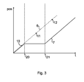
- Fig 3 is a schematic diagram illustrating program execution of the robot of Fig 1 , where there is an unhandled conveyor stoppage.
- the conveyor 3 stops, and the conveyor 3 starts moving again at a time 22.
- the stoppage between the times 20 and 22 is indicated by the fact that the solid conveyor line 7 is horizontal between these two times 20, 22. In other words, time passes without movement of the work object 2 on the conveyor.
- the program flow indicated by the dashed line 6, continues as if the work object 2 continues to move. This can result in kinematic limitations as a result of the limited work area 9.
- Fig 4 is a schematic diagram illustrating program execution of the robot of Fig 1 , where there is a conveyor stoppage which is handled. As in Fig 3 , there is a conveyor stoppage between times 20 and 22. Here, however, a controller of the robot 1 recognises the stoppage at some point after the stoppage at time 20, and suspends the program at time 21.
- the deviation of the conveyor in relation to a nominal speed can for example be detected in any one or in any combination of any of the following three ways:
- the actual conveyor position is compared with a reference conveyor position based on a time measurement from the beginning of the program multiplied by the nominal (expected) conveyor speed.
- the actual conveyor position is recorded in each programmed position by running the program with conveyor moving at correct, nominal, speed in a special "teach mode".
- the conveyor positions will then be included and saved along with the program.
- the recorded and actual position can be compared to determine if the conveyor is in its correct position
- the nominal speed can be a configured speed, or can vary from program to program.
- the nominal speed is a speed of the conveyor which is measured at a time when the robot and conveyor are operating normally.
- the nominal speed can be a speed which is the same for an entire production line of the entire plant, or it could be a speed which pertains only to a subset of the plant, such as only the production stage in question.
- the conveyor may not come to a complete stop.
- the conveyor can also slow down, whereby the controller recognises the reduction in speed and acts the same way.
- the robot has a nominal, normal speed, whereby any deviation from this can be detected. The deviation can be considered to have occurred if the speed of the conveyor 3 deviates from the nominal speed by more than a predetermined percentage. Alternatively, the conveyor 3 is considered to have deviated from the nominal speed if an accumulated lag time of the conveyor exceeds a threshold lag time.
- a waiting routine can be executed.
- the waiting routine is as simple as keeping the robot stationary, optionally preceded by moving the robot away from the work object 2. It is to be noted that the position 14 in the program flow, corresponding to point 11, where the program flow is suspended, is not a pre-programmed waiting position. On the contrary, point 14 is a dynamically generated waiting position.
- the function may be switched on and off anywhere in the program by a program instruction as inserted by a programmer. This allows the programmer to, for example, exclude the possibility of creating waiting positions in sensitive parts of the movement program where a waiting position would be detrimental to the result of the program.
- waiting positions in the control program for the robot had to be pre-programmed, e.g. by manually entering waiting positions in the program or running one or more teaching runs of a control program of a robot to set the waiting position a certain points of the control program.
- the conveyor 3 starts again. At some point after the start, this is detected by the controller of the robot 1.
- the conveyor 3 has caught up with the position 14 of the control program, whereby the program flow resumes at point 11'.
- the controller knows when to resume the program flow by measuring the time between 20 and 21, multiplying this time with the conveyor speed, and adding the resulting distance to the position 15 when the conveyor stopped. In other words, the controller calculates the position 14, and resumes when the conveyor is at, or approaches this position 14.
- the conveyor 3 and the program flow are again synchronised.
- the stoppage is determined as a trigger for creating a waiting position if an accumulation of stoppages exceeds a threshold time. The accumulation is then calculated since the most recent previous waiting position correction, or since production start, if no waiting position has been created yet.
- Fig 5 illustrates the path of a program flow of the robot in Fig 1 .
- the program runs without interruptions from point 10 to point 11 and finally to point 12, corresponding to points 10, 11 and 12 of Fig 2 .
- Fig 6 illustrates the path of a program flow of the robot in Fig 1 where there is an interruption.
- the controller of the robot detects that the conveyor has stopped. The controller then creates a waiting position at point 11.
- a virtual surface 16 is created.
- This virtual surface 16 is a geometric construction in space (i.e. not a physical surface), which is used to control a tool of the robot 1. For example, if the tool is a spray applicator for paint, the applicator is switched off when a part of the robot 1, e.g. the applicator, passes the virtual surface 16. Passing the virtual surface can for example be determined when any part of the applicator (or any other predetermined part of the industrial robot 1) passes the virtual surface 16, or when a specific point of the applicator (or any other predetermined part of the industrial robot 1) passes the surface 16. The robot then waits in position 11 until the controller determines that it is time to resume the program. When the same part of the robot as before, e.g.
- the applicator passes the virtual surface (now in the opposite direction from before), the applicator is switched on.
- the virtual surface 16 is created some distance from the work object 2. This allows for a smooth transition from spraying paint to stopping the spraying, and similarly, a smooth transition when the paint spraying is resumed. This solves the problem which may arise if the paint spraying is stopped or resumed abruptly, resulting in undesired, and visible and/or tactile artefacts from the suspended painting.
- the virtual surface 16 can be of any suitable geometry, including, but not limited to, a plane, a partial spherical surface, any other curved surface or a virtual surface of any other suitable shape.
- the spray applicator can be switched off when it reaches a certain distance from the work object, or the spray applicator can be switched off once the robot rests in its waiting position.
- a retracted position is created based on the programmed position, thereby moving the applicator out from the object. This will create a path outside the already programmed path.
- the painting may be suspended/started after a time delay from the programmed position.
- the controller can create a virtual surface for suspending the painting along the path before the robot stopped. In this case the robot will reverse along the path until it reaches a position before the virtual surface where it waits for the conveyor and then uses the same virtual surface to start painting again.
- the painting may also be suspended/started after a time delay from the programmed position
- paint/air flow may also be ramped down when suspending painting and ramped up again when starting.
- the ramping period may be adjustable.
- the method described above can be packaged as a software package for execution in a controller of a robot.
Landscapes
- Engineering & Computer Science (AREA)
- General Engineering & Computer Science (AREA)
- Manufacturing & Machinery (AREA)
- Quality & Reliability (AREA)
- Physics & Mathematics (AREA)
- General Physics & Mathematics (AREA)
- Automation & Control Theory (AREA)
- Robotics (AREA)
- Mechanical Engineering (AREA)
- Manipulator (AREA)
- Numerical Control (AREA)
Priority Applications (2)
| Application Number | Priority Date | Filing Date | Title |
|---|---|---|---|
| EP08162897.6A EP2159657B1 (de) | 2008-08-25 | 2008-08-25 | Verfahren und Steuersystem zur Synchronisation eines Roboters und eines Förderbandes |
| ES08162897.6T ES2647269T3 (es) | 2008-08-25 | 2008-08-25 | Método y sistema de control para la sincronización de un robot y un transportador |
Applications Claiming Priority (1)
| Application Number | Priority Date | Filing Date | Title |
|---|---|---|---|
| EP08162897.6A EP2159657B1 (de) | 2008-08-25 | 2008-08-25 | Verfahren und Steuersystem zur Synchronisation eines Roboters und eines Förderbandes |
Publications (2)
| Publication Number | Publication Date |
|---|---|
| EP2159657A1 true EP2159657A1 (de) | 2010-03-03 |
| EP2159657B1 EP2159657B1 (de) | 2017-10-04 |
Family
ID=40210477
Family Applications (1)
| Application Number | Title | Priority Date | Filing Date |
|---|---|---|---|
| EP08162897.6A Active EP2159657B1 (de) | 2008-08-25 | 2008-08-25 | Verfahren und Steuersystem zur Synchronisation eines Roboters und eines Förderbandes |
Country Status (2)
| Country | Link |
|---|---|
| EP (1) | EP2159657B1 (de) |
| ES (1) | ES2647269T3 (de) |
Cited By (4)
| Publication number | Priority date | Publication date | Assignee | Title |
|---|---|---|---|---|
| CN103853134A (zh) * | 2012-11-30 | 2014-06-11 | 发纳科机器人美国公司 | 使喷漆机器人同步的方法 |
| CN106598110B (zh) * | 2015-10-19 | 2018-09-04 | 沈阳新松机器人自动化股份有限公司 | 新型喷涂机器人正压防爆系统 |
| CN111483808A (zh) * | 2019-01-25 | 2020-08-04 | 发那科株式会社 | 机器人控制装置及管理系统 |
| CN111975746A (zh) * | 2019-05-24 | 2020-11-24 | 精工爱普生株式会社 | 机器人的控制方法 |
Citations (4)
| Publication number | Priority date | Publication date | Assignee | Title |
|---|---|---|---|---|
| US4170751A (en) | 1978-02-02 | 1979-10-09 | General Motors Corporation | Electronic control for a mechanized spray painting system |
| GB2045463A (en) * | 1979-04-03 | 1980-10-29 | Hall Automation Ltd | Arrangement for controlling an operation performed on a workpiece |
| US4810538A (en) * | 1987-04-02 | 1989-03-07 | Behr-Industrieanlagen Gmbh & Co. | Method for automatic coating of workpieces |
| WO2005063454A1 (en) | 2003-12-22 | 2005-07-14 | Abb As | Control method device and system for robot applications |
-
2008
- 2008-08-25 ES ES08162897.6T patent/ES2647269T3/es active Active
- 2008-08-25 EP EP08162897.6A patent/EP2159657B1/de active Active
Patent Citations (4)
| Publication number | Priority date | Publication date | Assignee | Title |
|---|---|---|---|---|
| US4170751A (en) | 1978-02-02 | 1979-10-09 | General Motors Corporation | Electronic control for a mechanized spray painting system |
| GB2045463A (en) * | 1979-04-03 | 1980-10-29 | Hall Automation Ltd | Arrangement for controlling an operation performed on a workpiece |
| US4810538A (en) * | 1987-04-02 | 1989-03-07 | Behr-Industrieanlagen Gmbh & Co. | Method for automatic coating of workpieces |
| WO2005063454A1 (en) | 2003-12-22 | 2005-07-14 | Abb As | Control method device and system for robot applications |
Cited By (5)
| Publication number | Priority date | Publication date | Assignee | Title |
|---|---|---|---|---|
| CN103853134A (zh) * | 2012-11-30 | 2014-06-11 | 发纳科机器人美国公司 | 使喷漆机器人同步的方法 |
| CN106598110B (zh) * | 2015-10-19 | 2018-09-04 | 沈阳新松机器人自动化股份有限公司 | 新型喷涂机器人正压防爆系统 |
| CN111483808A (zh) * | 2019-01-25 | 2020-08-04 | 发那科株式会社 | 机器人控制装置及管理系统 |
| CN111975746A (zh) * | 2019-05-24 | 2020-11-24 | 精工爱普生株式会社 | 机器人的控制方法 |
| CN111975746B (zh) * | 2019-05-24 | 2023-04-18 | 精工爱普生株式会社 | 机器人的控制方法 |
Also Published As
| Publication number | Publication date |
|---|---|
| EP2159657B1 (de) | 2017-10-04 |
| ES2647269T3 (es) | 2017-12-20 |
Similar Documents
| Publication | Publication Date | Title |
|---|---|---|
| US11548153B2 (en) | Robot comprising safety system ensuring stopping time and distance | |
| US20180333849A1 (en) | Robot system | |
| EP2159657B1 (de) | Verfahren und Steuersystem zur Synchronisation eines Roboters und eines Förderbandes | |
| US10105842B2 (en) | Operation program creating method and control method of robot | |
| CN107850884A (zh) | 用于非生产时间运动的轨迹确定方法 | |
| JP6211240B1 (ja) | 数値制御装置 | |
| CN111699079B (zh) | 协调系统、操作设备和方法 | |
| US11717961B2 (en) | Robot control method and robot control device | |
| JPS5916286B2 (ja) | 工業用ロボツトの動作制御方法 | |
| EP3817897A1 (de) | Verfahren und steuersystem zur steuerung eines industriellen stellantriebs | |
| CN110053042B (zh) | 机器人控制装置 | |
| JP7070114B2 (ja) | ロボット制御装置及びロボット制御方法 | |
| CN111699078A (zh) | 机器人的运行 | |
| CN116890335A (zh) | 机器人控制装置、机器人控制方法及存储介质 | |
| JP7460800B2 (ja) | ロボット制御装置及びロボットシステム | |
| US20220288785A1 (en) | Control device, control method, and program | |
| JP7684434B2 (ja) | ロボットシステムおよびロボット | |
| TW202202955A (zh) | 於弧形路徑中控制端效器追蹤物件的方法 | |
| JP7560872B2 (ja) | ロボットの動作制御データ生成装置及び動作制御データ生成方法 | |
| JP2505394B2 (ja) | 産業用ロボットの加速度変化を利用した制御方法 | |
| KR102675144B1 (ko) | 로봇 이동위치 동기출력 로봇제어장치 | |
| KR20210090020A (ko) | 로봇 제어 시스템 및 방법 | |
| JPH0569357A (ja) | ロボツトのコンベヤ追従制御方式 | |
| JPH0985657A (ja) | ロボットの制御装置 | |
| Olofsson et al. | Optimal tracking and identification of paths for industrial robots |
Legal Events
| Date | Code | Title | Description |
|---|---|---|---|
| PUAI | Public reference made under article 153(3) epc to a published international application that has entered the european phase |
Free format text: ORIGINAL CODE: 0009012 |
|
| 17P | Request for examination filed |
Effective date: 20080825 |
|
| AK | Designated contracting states |
Kind code of ref document: A1 Designated state(s): AT BE BG CH CY CZ DE DK EE ES FI FR GB GR HR HU IE IS IT LI LT LU LV MC MT NL NO PL PT RO SE SI SK TR |
|
| AX | Request for extension of the european patent |
Extension state: AL BA MK RS |
|
| 17Q | First examination report despatched |
Effective date: 20100419 |
|
| AKX | Designation fees paid |
Designated state(s): AT BE BG CH CY CZ DE DK EE ES FI FR GB GR HR HU IE IS IT LI LT LU LV MC MT NL NO PL PT RO SE SI SK TR |
|
| REG | Reference to a national code |
Ref country code: DE Ref legal event code: R079 Ref document number: 602008052334 Country of ref document: DE Free format text: PREVIOUS MAIN CLASS: G05B0019418000 Ipc: B05B0013040000 |
|
| GRAP | Despatch of communication of intention to grant a patent |
Free format text: ORIGINAL CODE: EPIDOSNIGR1 |
|
| RIC1 | Information provided on ipc code assigned before grant |
Ipc: B05B 13/04 20060101AFI20170331BHEP Ipc: B25J 9/00 20060101ALI20170331BHEP Ipc: G05B 19/418 20060101ALI20170331BHEP |
|
| INTG | Intention to grant announced |
Effective date: 20170502 |
|
| GRAS | Grant fee paid |
Free format text: ORIGINAL CODE: EPIDOSNIGR3 |
|
| GRAA | (expected) grant |
Free format text: ORIGINAL CODE: 0009210 |
|
| AK | Designated contracting states |
Kind code of ref document: B1 Designated state(s): AT BE BG CH CY CZ DE DK EE ES FI FR GB GR HR HU IE IS IT LI LT LU LV MC MT NL NO PL PT RO SE SI SK TR |
|
| REG | Reference to a national code |
Ref country code: GB Ref legal event code: FG4D |
|
| REG | Reference to a national code |
Ref country code: CH Ref legal event code: EP |
|
| REG | Reference to a national code |
Ref country code: AT Ref legal event code: REF Ref document number: 933510 Country of ref document: AT Kind code of ref document: T Effective date: 20171015 |
|
| REG | Reference to a national code |
Ref country code: IE Ref legal event code: FG4D |
|
| REG | Reference to a national code |
Ref country code: DE Ref legal event code: R096 Ref document number: 602008052334 Country of ref document: DE |
|
| REG | Reference to a national code |
Ref country code: ES Ref legal event code: FG2A Ref document number: 2647269 Country of ref document: ES Kind code of ref document: T3 Effective date: 20171220 |
|
| REG | Reference to a national code |
Ref country code: NL Ref legal event code: MP Effective date: 20171004 |
|
| REG | Reference to a national code |
Ref country code: LT Ref legal event code: MG4D |
|
| REG | Reference to a national code |
Ref country code: AT Ref legal event code: MK05 Ref document number: 933510 Country of ref document: AT Kind code of ref document: T Effective date: 20171004 |
|
| PG25 | Lapsed in a contracting state [announced via postgrant information from national office to epo] |
Ref country code: NL Free format text: LAPSE BECAUSE OF FAILURE TO SUBMIT A TRANSLATION OF THE DESCRIPTION OR TO PAY THE FEE WITHIN THE PRESCRIBED TIME-LIMIT Effective date: 20171004 |
|
| PG25 | Lapsed in a contracting state [announced via postgrant information from national office to epo] |
Ref country code: NO Free format text: LAPSE BECAUSE OF FAILURE TO SUBMIT A TRANSLATION OF THE DESCRIPTION OR TO PAY THE FEE WITHIN THE PRESCRIBED TIME-LIMIT Effective date: 20180104 Ref country code: SE Free format text: LAPSE BECAUSE OF FAILURE TO SUBMIT A TRANSLATION OF THE DESCRIPTION OR TO PAY THE FEE WITHIN THE PRESCRIBED TIME-LIMIT Effective date: 20171004 Ref country code: LT Free format text: LAPSE BECAUSE OF FAILURE TO SUBMIT A TRANSLATION OF THE DESCRIPTION OR TO PAY THE FEE WITHIN THE PRESCRIBED TIME-LIMIT Effective date: 20171004 Ref country code: FI Free format text: LAPSE BECAUSE OF FAILURE TO SUBMIT A TRANSLATION OF THE DESCRIPTION OR TO PAY THE FEE WITHIN THE PRESCRIBED TIME-LIMIT Effective date: 20171004 |
|
| PG25 | Lapsed in a contracting state [announced via postgrant information from national office to epo] |
Ref country code: GR Free format text: LAPSE BECAUSE OF FAILURE TO SUBMIT A TRANSLATION OF THE DESCRIPTION OR TO PAY THE FEE WITHIN THE PRESCRIBED TIME-LIMIT Effective date: 20180105 Ref country code: BG Free format text: LAPSE BECAUSE OF FAILURE TO SUBMIT A TRANSLATION OF THE DESCRIPTION OR TO PAY THE FEE WITHIN THE PRESCRIBED TIME-LIMIT Effective date: 20180104 Ref country code: IS Free format text: LAPSE BECAUSE OF FAILURE TO SUBMIT A TRANSLATION OF THE DESCRIPTION OR TO PAY THE FEE WITHIN THE PRESCRIBED TIME-LIMIT Effective date: 20180204 Ref country code: HR Free format text: LAPSE BECAUSE OF FAILURE TO SUBMIT A TRANSLATION OF THE DESCRIPTION OR TO PAY THE FEE WITHIN THE PRESCRIBED TIME-LIMIT Effective date: 20171004 Ref country code: AT Free format text: LAPSE BECAUSE OF FAILURE TO SUBMIT A TRANSLATION OF THE DESCRIPTION OR TO PAY THE FEE WITHIN THE PRESCRIBED TIME-LIMIT Effective date: 20171004 Ref country code: LV Free format text: LAPSE BECAUSE OF FAILURE TO SUBMIT A TRANSLATION OF THE DESCRIPTION OR TO PAY THE FEE WITHIN THE PRESCRIBED TIME-LIMIT Effective date: 20171004 |
|
| RAP2 | Party data changed (patent owner data changed or rights of a patent transferred) |
Owner name: ABB SCHWEIZ AG |
|
| REG | Reference to a national code |
Ref country code: DE Ref legal event code: R097 Ref document number: 602008052334 Country of ref document: DE |
|
| PG25 | Lapsed in a contracting state [announced via postgrant information from national office to epo] |
Ref country code: DK Free format text: LAPSE BECAUSE OF FAILURE TO SUBMIT A TRANSLATION OF THE DESCRIPTION OR TO PAY THE FEE WITHIN THE PRESCRIBED TIME-LIMIT Effective date: 20171004 Ref country code: CZ Free format text: LAPSE BECAUSE OF FAILURE TO SUBMIT A TRANSLATION OF THE DESCRIPTION OR TO PAY THE FEE WITHIN THE PRESCRIBED TIME-LIMIT Effective date: 20171004 Ref country code: EE Free format text: LAPSE BECAUSE OF FAILURE TO SUBMIT A TRANSLATION OF THE DESCRIPTION OR TO PAY THE FEE WITHIN THE PRESCRIBED TIME-LIMIT Effective date: 20171004 Ref country code: SK Free format text: LAPSE BECAUSE OF FAILURE TO SUBMIT A TRANSLATION OF THE DESCRIPTION OR TO PAY THE FEE WITHIN THE PRESCRIBED TIME-LIMIT Effective date: 20171004 |
|
| PLBE | No opposition filed within time limit |
Free format text: ORIGINAL CODE: 0009261 |
|
| STAA | Information on the status of an ep patent application or granted ep patent |
Free format text: STATUS: NO OPPOSITION FILED WITHIN TIME LIMIT |
|
| REG | Reference to a national code |
Ref country code: FR Ref legal event code: PLFP Year of fee payment: 11 |
|
| PG25 | Lapsed in a contracting state [announced via postgrant information from national office to epo] |
Ref country code: PL Free format text: LAPSE BECAUSE OF FAILURE TO SUBMIT A TRANSLATION OF THE DESCRIPTION OR TO PAY THE FEE WITHIN THE PRESCRIBED TIME-LIMIT Effective date: 20171004 Ref country code: RO Free format text: LAPSE BECAUSE OF FAILURE TO SUBMIT A TRANSLATION OF THE DESCRIPTION OR TO PAY THE FEE WITHIN THE PRESCRIBED TIME-LIMIT Effective date: 20171004 |
|
| 26N | No opposition filed |
Effective date: 20180705 |
|
| PG25 | Lapsed in a contracting state [announced via postgrant information from national office to epo] |
Ref country code: SI Free format text: LAPSE BECAUSE OF FAILURE TO SUBMIT A TRANSLATION OF THE DESCRIPTION OR TO PAY THE FEE WITHIN THE PRESCRIBED TIME-LIMIT Effective date: 20171004 |
|
| PG25 | Lapsed in a contracting state [announced via postgrant information from national office to epo] |
Ref country code: MC Free format text: LAPSE BECAUSE OF FAILURE TO SUBMIT A TRANSLATION OF THE DESCRIPTION OR TO PAY THE FEE WITHIN THE PRESCRIBED TIME-LIMIT Effective date: 20171004 |
|
| REG | Reference to a national code |
Ref country code: CH Ref legal event code: PL |
|
| GBPC | Gb: european patent ceased through non-payment of renewal fee |
Effective date: 20180825 |
|
| PG25 | Lapsed in a contracting state [announced via postgrant information from national office to epo] |
Ref country code: LU Free format text: LAPSE BECAUSE OF NON-PAYMENT OF DUE FEES Effective date: 20180825 Ref country code: CH Free format text: LAPSE BECAUSE OF NON-PAYMENT OF DUE FEES Effective date: 20180831 Ref country code: LI Free format text: LAPSE BECAUSE OF NON-PAYMENT OF DUE FEES Effective date: 20180831 |
|
| REG | Reference to a national code |
Ref country code: BE Ref legal event code: MM Effective date: 20180831 |
|
| PG25 | Lapsed in a contracting state [announced via postgrant information from national office to epo] |
Ref country code: BE Free format text: LAPSE BECAUSE OF NON-PAYMENT OF DUE FEES Effective date: 20180831 |
|
| PG25 | Lapsed in a contracting state [announced via postgrant information from national office to epo] |
Ref country code: GB Free format text: LAPSE BECAUSE OF NON-PAYMENT OF DUE FEES Effective date: 20180825 |
|
| PG25 | Lapsed in a contracting state [announced via postgrant information from national office to epo] |
Ref country code: MT Free format text: LAPSE BECAUSE OF NON-PAYMENT OF DUE FEES Effective date: 20180825 |
|
| PG25 | Lapsed in a contracting state [announced via postgrant information from national office to epo] |
Ref country code: TR Free format text: LAPSE BECAUSE OF FAILURE TO SUBMIT A TRANSLATION OF THE DESCRIPTION OR TO PAY THE FEE WITHIN THE PRESCRIBED TIME-LIMIT Effective date: 20171004 |
|
| PG25 | Lapsed in a contracting state [announced via postgrant information from national office to epo] |
Ref country code: PT Free format text: LAPSE BECAUSE OF FAILURE TO SUBMIT A TRANSLATION OF THE DESCRIPTION OR TO PAY THE FEE WITHIN THE PRESCRIBED TIME-LIMIT Effective date: 20171004 Ref country code: HU Free format text: LAPSE BECAUSE OF FAILURE TO SUBMIT A TRANSLATION OF THE DESCRIPTION OR TO PAY THE FEE WITHIN THE PRESCRIBED TIME-LIMIT; INVALID AB INITIO Effective date: 20080825 |
|
| PG25 | Lapsed in a contracting state [announced via postgrant information from national office to epo] |
Ref country code: CY Free format text: LAPSE BECAUSE OF FAILURE TO SUBMIT A TRANSLATION OF THE DESCRIPTION OR TO PAY THE FEE WITHIN THE PRESCRIBED TIME-LIMIT Effective date: 20171004 Ref country code: IE Free format text: LAPSE BECAUSE OF NON-PAYMENT OF DUE FEES Effective date: 20180825 |
|
| PGFP | Annual fee paid to national office [announced via postgrant information from national office to epo] |
Ref country code: IT Payment date: 20210830 Year of fee payment: 14 Ref country code: FR Payment date: 20210819 Year of fee payment: 14 |
|
| PG25 | Lapsed in a contracting state [announced via postgrant information from national office to epo] |
Ref country code: IT Free format text: LAPSE BECAUSE OF NON-PAYMENT OF DUE FEES Effective date: 20220825 Ref country code: FR Free format text: LAPSE BECAUSE OF NON-PAYMENT OF DUE FEES Effective date: 20220831 |
|
| PGFP | Annual fee paid to national office [announced via postgrant information from national office to epo] |
Ref country code: ES Payment date: 20250925 Year of fee payment: 18 |
|
| PGFP | Annual fee paid to national office [announced via postgrant information from national office to epo] |
Ref country code: DE Payment date: 20250820 Year of fee payment: 18 |