EP2159726A1 - Clientseitige Mehrkomponenten-Bildzusammensetzung - Google Patents
Clientseitige Mehrkomponenten-Bildzusammensetzung Download PDFInfo
- Publication number
- EP2159726A1 EP2159726A1 EP09251857A EP09251857A EP2159726A1 EP 2159726 A1 EP2159726 A1 EP 2159726A1 EP 09251857 A EP09251857 A EP 09251857A EP 09251857 A EP09251857 A EP 09251857A EP 2159726 A1 EP2159726 A1 EP 2159726A1
- Authority
- EP
- European Patent Office
- Prior art keywords
- image
- image data
- client
- data records
- server
- Prior art date
- Legal status (The legal status is an assumption and is not a legal conclusion. Google has not performed a legal analysis and makes no representation as to the accuracy of the status listed.)
- Granted
Links
Images


Classifications
-
- G—PHYSICS
- G16—INFORMATION AND COMMUNICATION TECHNOLOGY [ICT] SPECIALLY ADAPTED FOR SPECIFIC APPLICATION FIELDS
- G16H—HEALTHCARE INFORMATICS, i.e. INFORMATION AND COMMUNICATION TECHNOLOGY [ICT] SPECIALLY ADAPTED FOR THE HANDLING OR PROCESSING OF MEDICAL OR HEALTHCARE DATA
- G16H30/00—ICT specially adapted for the handling or processing of medical images
- G16H30/40—ICT specially adapted for the handling or processing of medical images for processing medical images, e.g. editing
-
- G—PHYSICS
- G16—INFORMATION AND COMMUNICATION TECHNOLOGY [ICT] SPECIALLY ADAPTED FOR SPECIFIC APPLICATION FIELDS
- G16H—HEALTHCARE INFORMATICS, i.e. INFORMATION AND COMMUNICATION TECHNOLOGY [ICT] SPECIALLY ADAPTED FOR THE HANDLING OR PROCESSING OF MEDICAL OR HEALTHCARE DATA
- G16H30/00—ICT specially adapted for the handling or processing of medical images
- G16H30/20—ICT specially adapted for the handling or processing of medical images for handling medical images, e.g. DICOM, HL7 or PACS
-
- G—PHYSICS
- G16—INFORMATION AND COMMUNICATION TECHNOLOGY [ICT] SPECIALLY ADAPTED FOR SPECIFIC APPLICATION FIELDS
- G16H—HEALTHCARE INFORMATICS, i.e. INFORMATION AND COMMUNICATION TECHNOLOGY [ICT] SPECIALLY ADAPTED FOR THE HANDLING OR PROCESSING OF MEDICAL OR HEALTHCARE DATA
- G16H40/00—ICT specially adapted for the management or administration of healthcare resources or facilities; ICT specially adapted for the management or operation of medical equipment or devices
- G16H40/60—ICT specially adapted for the management or administration of healthcare resources or facilities; ICT specially adapted for the management or operation of medical equipment or devices for the operation of medical equipment or devices
- G16H40/67—ICT specially adapted for the management or administration of healthcare resources or facilities; ICT specially adapted for the management or operation of medical equipment or devices for the operation of medical equipment or devices for remote operation
Definitions
- the present invention relates to tissue sample analysis and imaging. More particularly, but not exclusively, this invention relates to digital images for telepathology being accessed on a storage server by a remote client.
- Digital imaging systems are now commonly used for the acquisition and analysis of images of tissue samples and cell mono-layers.
- Systems such as Ariol® produced by Applied Imaging / Genetix have been developed for the digital capture of both bright field and fluorescent images, as well as the automated quantitative analysis of immunohistochemistry- (IHC) and fluorescent in situ hybridization- (FISH) labeled samples.
- IHC immunohistochemistry-
- FISH fluorescent in situ hybridization-
- the digital image data may comprise multiple component channels, for example both bright field and multiple fluorescent labeled images, derived from a given sample.
- a high bandwidth network such as a hospital picture archiving and communications systems (PACS) network
- PACS picture archiving and communications systems
- the client may then run applications locally to process and/or analyze the image files as desired.
- the image files may be too large for this to be feasible and in this situation the arrangement of server and client is often such that, in order to reduce the required communication bandwidth between the server and client, as little information as possible is transferred from the server to the client.
- application software generating the image to be displayed may be executed on the server and only necessary display information for the client user is transmitted to the client. This is known as a "thin client" approach.
- Such remote access may be configured such that the client may interact with the server such that, as well as requesting particular images or information from the server, the client may actively cause processing to happen at the server.
- Systems such as those provided by Citrix® Systems can provide the resources for this variety of interaction to occur.
- the present invention provides a method of displaying a client-side multi-component image, comprising: storing in a server a plurality of image component channels derived from captured images of a sample, said plurality of image component channels being stored in the form of a plurality of image data records; requesting by a client one or more of said plurality of image data records; transmitting from the server to the client the one or more of said plurality of image data records requested in said requesting step; compositing the client-side multi-component image from the one or more of said plurality of image data records transmitted in said transmitting step; and displaying the composited client-side multi-component image.
- the client could be provided with a more flexible system, in which the separate channel information is retained by storing in the server a plurality of image data records, the image data records representing component channels derived from the captured images.
- the client can then request only those channels which are of interest, thus saving transmission bandwidth.
- the component channels are then composited at the client to form a client-side multi-component image, which is then displayed.
- the client then has the opportunity to reconfigure the displayed image, for example by toggling one component channel on and off, to more accurately view the contribution of that particular component channel to the displayed image.
- the plurality of image data records comprises a hierarchy of image data records for each component channel, each hierarchy comprising a set of image data records, each set of image data records comprising image data records having different resolutions from each other; the method further comprising: at said requesting step the client specifying a desired resolution; and at said transmitting step the server selecting and transmitting image data records appropriate to the desired resolution that has been requested.
- the desired resolution may be requested directly or indirectly by the client, and the above wording covers both possibilities.
- the user at the client side will issue commands to the client machine in terms of the extent of a viewing window.
- the client machine may translate that into a desired resolution, and transmit that as a request to the server machine, so that the client directly requests a desired resolution.
- the client machine may simply pass to the server machine the viewing window coordinates, and leave it to the server to translate this information into a desired resolution, so that the client is indirectly requesting a desired resolution.
- the bandwidth requirements of the system may be further reduced, since for each component channel the server stores a hierarchy of image data records with the levels in the hierarchy representing points in a range of resolutions.
- the user at the client can then, for example initially, request only low resolution versions of the selected component channels to get an overview of the captured images, then later requesting higher resolution versions to examine the images in more detail, either directly or indirectly as discussed above.
- the plurality of image data records comprises a set of tiles for each image component channel, the set of tiles together forming the image component channel; the method further comprising at said requesting step specifying a desired portion of the captured images; and at said transmitting step transmitting image data records appropriate to the desired portion of the captured images.
- the bandwidth requirements of the system may be further reduced, since a set of tiles makes up each image component channel derived from the captured images.
- the user at the client can then request only those areas of the selected component channels that are of interest, corresponding to one particular region of the captured images.
- said compositing further comprises stitching more than one tile of said set of tiles together to form the composited client-side multi-component image.
- the client user may be presented with a conveniently presented image composed of a selection of tiles of interest, stitched together to present a single image covering the area of those tiles.
- the client user may pan across the composited client-side multi-component image, further tiles that are required to complete portions of the image coming into view only being retrieved from the server when they are required for display.
- said plurality of image data records comprises image data records corresponding to different focal depths of the captured images, the method further comprising: at said requesting step the client specifying a desired focal depth of the captured images; and at said transmitting step the server transmitting image data records appropriate to the desired focal depth of the captured images.
- a sample under investigation will typically have a finite depth, depending on the magnification at which the images are being captured and the nature of the sample it can be advantageous for images of the sample to be captured as images at a range of focal depths.
- image data sets are referred to as z-stacked data sets.
- the client user may then examine the range of focal depth images to determine the focal depth at which the image is most clearly viewable and/or useful for analysis. Alternatively this determination may be carried out by software analysis, for example by contrast analysis, maximum intensity projection, or SUM or X-ray projection which are all well known techniques in imaging, in particular medical imaging.
- the image component channels of the captured images are monochromatic. In this manner the bandwidth requirements of the system may be further reduced, since for each image component channel no color information need be stored or transmitted.
- the storing step may beneficially comprise compressing the captured images into the image data records using an image data compression protocol, for example taken from: JPEG, JBIG, PNG, WBMP, BMP, GIF, ICER, ILBM, PCX, PGF, TGA and TIFF, so that each image data record includes a compressed version of the captured images.
- image data records may in parallel include un-compressed, so-called raw, versions of the same image component channels, or the compressed versions may be the only ones stored.
- JPEG, JBIG, PNG, WBMP, BMP, GIF, ICER, ILBM, PCX, PGF, TGA and TIFF is a non-exhaustive list provided by way of example only. It will be understood that the invention may be applied to other existing data formats, as well as data formats developed in the future.
- a key advantage of this approach in the context of a narrow or limited bandwidth communication between client and server, such as a low specification LAN network, or an internet connection, is that the user at the client side retains the freedom to toggle between viewing different combinations of image component channels in the client side display, but it is only necessary to transmit from the client to the server a compressed version of each image component channel.
- This approach is to be contrasted with the prior art approach of transmitting a compressed version of an RGB image of the already-composited image component channels over the network channel.
- the approach of the server transmitting each image component channel individually in compressed form to the client means that the user at the client side can adjust which combination of image component channels are composited at the client side without having to retransmit the composited image over the network each time the combination of image component channels to be viewed is changed by the user. All that is required is that a compositor is present on the client to perform the compositing function. This need only be a very primitive piece of applications software capable of combining the different image component channels. A full blown renderer is not required.
- the applications software may be permanently resident on the client, or supplied on demand by the server to the client as a downloadable component.
- the compositing step comprises transforming the one or more of said plurality of image data records transmitted in said transmitting step into an RGB image.
- the compositing step comprises transforming the one or more of said plurality of image data records transmitted in said transmitting step into a compressed image format, for example taken from: JPEG, JBIG, PNG, WBMP, BMP, GIF, ICER, ILBM, PCX, PGF, TGA and TIFF.
- the captured images could take a variety of forms.
- the captured images are images of a tissue sample.
- the captured images are images of a cell mono-layer. Whilst both of these embodiments will typically involve two-dimensional (2D) data, from which a 2D composited client-side multi-component image is generated, these could equally involve three-dimensional (3D) data, such as that from a tomographic scan, which could then be rendered in 2D on a display screen, or in 3D as a holographic display.
- 2D two-dimensional
- 3D three-dimensional
- the image component channels of the captured images could derive from a range of sources.
- the image component channels of the captured images include fluorescent imaging information, either exclusively or in combination with other channels, for example a bright field image channel, a dark field image channel and/or one or more synthetic image channels derived from intermediate image processing of the raw acquired image data.
- This fluorescent imaging information could for example result from a fluorescent in situ hybridization (FISH) labeled sample or from an immunohistochemistry labeled sample.
- FISH fluorescent in situ hybridization
- the image component channels of the captured images comprise analysis data created after capturing of the captured images.
- analysis data such as a mask indicating regions of interest in the image may also be selectively downloaded by the user.
- the analysis data is user-generated, such as a user-drawn contour enclosing a region of interest.
- the analysis data is software-generated, such as graphical information derived from software-based counting of features in the image.
- analysis may be performed at the client-side and the results of that analysis then up-loaded to the server, the method in this embodiment comprising the further steps of:
- the additional image information may be stored at the server as text or other non-image data, for example in a file header, or may be stored as further image data, for example an extra image component channel to be stored with the other pre-existing image component channels for that sample, or as a combination of both.
- analysis data generated by a particular client user may be stored with its associated captured image(s) on the server, such that it is available for later viewing in association with the captured image(s) either by the same user, or by a different user, possibly at a different client machine.
- the original user may return to some analysis results at a later point in time, or alternatively another user may examiner those analysis results, for example to give a second opinion.
- the present invention provides a client apparatus, the client apparatus configured to:
- the present invention provides a server apparatus, the server apparatus configured to:
- the present invention provides a system for displaying a client-side multi-component image, the system comprising:
- Figure 1A schematically illustrates a microscope system for capturing images of a sample.
- the microscope unit 10 captures digital images of a sample under investigation and the digital images are transferred to computer 12 where they are stored.
- the microscope unit 10 can illuminate with white light for the capturing of bright field digital images, and can also illuminate with a range of specific wavelengths by means of a filter set for the excitation of particular fluorescent emissions.
- the slide holding the sample may be loaded manually by a user, but in the illustrated example the microscope unit 10 comprises a set of microscope slide racks and an automated slide loader, so that a series of slides may be selected, positioned under the microscope, imaged and returned to the slide racks.
- the computer 12 sends commands to the microscope unit 10 dictating which slides should be imaged, what magnifications they should be imaged at, which light source should be used to illuminate each slide, and so on.
- a user operating computer 12 may then examine those images, perform analysis on them, and so on.
- the example system illustrated is the Ariol® imaging system produced by Applied Imaging / Genetix.
- Figure 1B schematically illustrates the microscope system of Figure 1A connected to a server 14 and a network.
- the network consists of both computing devices 16 connected locally to the server 14, and of computing devices 18 located remote from the server 14, for example in a local area network (LAN) or via the internet.
- LAN local area network
- the captured images taken by microscope unit 10 are uploaded from computer 12 to the server 14, such that any of the other computing devices 16 or 18 connected to the server 14 may also view those captured images, perform analysis on them etc.
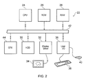
- FIG 2 schematically illustrates a general purpose computer system 22 (such as computers 12, 16 or 18 in Figures 1A and 1B ) configured to perform processing of captured images in accordance with an embodiment of the invention.
- the computer 22 includes a central processing unit (CPU) 24, a read only memory (ROM) 26, a random access memory (RAM) 28, a hard disk drive (HDD) 30, a display driver 32 and display 34, and a user input/output (I/O) circuit 36 with a keyboard 38 and mouse 40. These devices are connected via a common bus 42.
- the computer 22 also includes a graphics card 44 connected via the common bus 42.
- the graphics card includes a graphics processing unit (GPU) and random access memory tightly coupled to the GPU (GPU memory) (not shown in Figure 2 ).
- GPU graphics processing unit
- GPU memory GPU memory
- the CPU 24 may execute program instructions stored in the ROM 26, in the RAM 28 or on the hard disk drive 30 to carry out processing of captured images, for which associated data may be stored within the RAM 28 or the hard disk drive 30.
- the RAM 28 and hard disk drive 30 are collectively referred to as the system memory.
- the GPU may also execute program instructions to carry out processing of captured image data passed to it from the CPU.
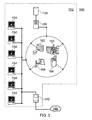
- FIG. 3 shows an example computer network which can be used in conjunction with embodiments of the invention.
- the network 150 comprises a local area network in a hospital 152.
- the hospital 152 is equipped with a number of workstations 154 which have access, via a local area network, to a hospital computer server 156 having an associated storage device 158.
- a PACS archive is stored on the storage device 158 so that data in the archive can be accessed from any of the workstations 154.
- One or more of the workstations 154 has access to a graphics card and to software for computer implementation of methods of client-side multi-component image composition as described hereinafter.
- the software may be stored locally at each workstation 154, or may be stored remotely and downloaded over the network 150 to a workstation 154 when needed.
- a number of medical imaging devices 160, 162, 164, 166 are connected to the hospital computer server 156 and imaging data collected with the devices 160, 162, 164, 166 can be stored directly into the PACS archive on the storage device 156.
- the local area network is connected to the internet 168 by a hospital internet server 170, which allows remote access to the PACS archive. This is of use for remote accessing of data and for transferring data between hospitals, for example, if a patient is moved, or to allow external research to be undertaken.
- One example use would be for a clinician to access and review sample images, such as a pathologist with tissue sample images.
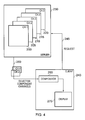
- Figure 4 schematically illustrates a server and client according to one embodiment of the present invention.
- a series of captured images of a sample have been processed and stored as a series of image data records 200, 205, 210, 215, 220 in the server 230.
- image data record 200 (also referred to as channel 1) derives from a bright field captured image of the sample.
- Image data records 205, 210, 215, 220 derive from a series of fluorescent illuminations of the sample at different wavelengths (also referred to as channels 2, 3, 4 and 5).
- client device 240 sends a request to server 230 over request path 245 for image data records to be transmitted over transmission path 250.
- client 240 has requested image data records 205 and 215 (i.e. channels 2 and 4), which are then transmitted over transmission path 250.
- compositor 260 then combines the image component channels 2 and 4 to generate a client-side multi-component image for display on display unit 270.
- the client device 240 is also a computer system such as that illustrated in Figure 2 and Figure 5 schematically shows some of the features of this computer system in more detail.
- the RAM 28 and hard disk drive 30 are shown collectively in Figure 5 as system memory 46.
- the image data records received from the server 230 over transmission path 250 are stored in the system memory 46.
- a first bus connection 42a connects between the system memory 46 and CPU 24.
- a second bus connection 42b connects between the CPU 24 and graphics card 44.
- a third bus connection 42c connects between the graphics card 44 and display 34.
- a fourth bus connection 42d connects between the user I/O 36 and the CPU 24.
- the CPU includes a CPU cache 50.
- the graphics card 44 includes a GPU 54 and a GPU memory 56.
- the GPU 54 includes circuitry for providing an accelerated graphics processing interface 60, a GPU cache I/O controller system 2, a processing engine 64 and a display I/O controller 66.
- the processing engine 64 is designed for optimized execution of the types of program instructions associated with compositing a multi-component image from received image data records.
- the user defines the required parameters using the keyboard 38 and mouse 40 in combination with a menu of options displayed on the display 34, for example using conventional techniques.
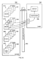
- FIG. 6 schematically illustrates the server and client accordingly to one embodiment of the present invention.
- Server 300 stores the image component channels which have been derived from captured images of a sample, these image component channels being stored in the form of image data records.
- the image data records are stored as a hierarchy of image data records 310, 315, 320 and 325, each level of the hierarchy comprising a set of image data records of a given resolution.
- the set of image data records 310 comprises 128 x 128 resolution records of each image component channel, the set of image data records 315 being of resolution 256 x 256, the set of image data records 320 being of resolution 512 x 512 and the set of image data records 325 being of resolution 1024 x 1024.
- each image component channel e.g. the set of 256 x 256 resolution image data records 315
- each image component channel is stored as a set of image data records of progressively increasing resolution (e.g. the channel 5 set of image data records 311, 316, 321 and 326).
- the client 330 sends a request to server 300, the request being transmitted via network interface 350, the request specifying both the image component channels required as well as the resolution at which they should be supplied.
- the request In the example illustrated channels 1, 2, 3 and 5 at resolution 256 x 256 are requested and the corresponding image data records are transmitted by server 300 via network interface 350 to the client 330.
- These image data records received at the client are then composited by a compositor 355 for display on the display unit 340. It will be understood that this compositing will typically be performed by a graphics card such as 44 illustrated in Figure 5 but for simplicity in this illustration it is only illustrated in its functional role as compositor 335.
- the client user operating client device 330 having viewed the composited image at 256 x 256 resolution, may, for example, then decide to zoom in on the image to examine the sample in greater detail and thus a further request will be transmitted over network interface 350 to server 300, for example requesting the same channel numbers but at resolution 512 x 512. Equally, the client user could decide to zoom in even further on just one channel, for example requesting only channel 5 at 1024 x 1024 resolution then being sent image data record 326 over network interface 350.
- FIG. 7A schematically illustrates a further variation on the arrangements schematically illustrated in Figure 6 .
- the hierarchy of image data records 310, 315, 320 and 325 comprises a set of tiles at each level of the hierarchy.
- Each tile is of the same resolution, in this example being 128 x 128, but the number of tiles for each image component channel increases as one moves through the hierarchy.
- each image component channel comprises only one tile at level 310, comprises four tiles at level 315, comprises 16 tiles at level 320 and comprises 64 tiles at level 325.
- the client 330 not only requests particular image component channels and resolution, but can further specify which tiles from a given level of the hierarchy are required.
- the client has requested two adjacent tiles from level 320 of the hierarchy to be transmitted for two image component channels. These have been received by the client, composited and displayed on display 340.
- FIG. 7A The tiles discussed in relation to Figure 7A are generated by repeatedly subdividing a tile corresponding to the coarsest level in to four, or more specifically 2 x 2 sub-units, as is illustrated in Figure 7B.
- Figure 7B illustrates a series of four subdivisions of a tile to produce the set of four smallest tiles illustrated. It will be appreciated that other subdivisions may be used, for example 2 x 3, 2 x 4, 3 x 4 etc. with the choice being up to the designer having regard to the intended uses.
- Figure 8 schematically illustrates a further example embodiment of the present invention.
- the client 330 it is not only possible for the client 330 to request image data records from the server 300, but also to generate and upload further image data records from the client 330 to server 300.
- a composited image 360 displayed on display unit 340 of the client 330 is modified to generate modified image 370.
- This modification may come about either by user or by software generated input as illustrated by item 380.
- the modification comprises highlighting three portions of the composited image which are of interest. These could for example represent cells in a tissue sample which are suspected of being cancerous.
- the client 330 then uploads the corresponding modification information to the server 300 via network interface 350.
- This modification information 390 in this example in the form of a mask, is then stored in a server as a further image data record.
- This new image data record is then available both to the uploading client and to other clients which have access to the server 300.
- one client user may identify samples or portions of samples interest and make these available to other users for discussion or confirmation.
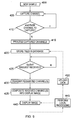
- Figure 9 schematically illustrates a series of steps carried out in one embodiment of the present invention.
- a new sample is ready to be imaged.
- a first image is captured of the sample to provide a first image component channel.
- a first image component channel For example this could comprise a bright field illumination of the sample.
- this could comprise illuminating the sample with several different wavelengths of light in succession in order to stimulate various fluorescent in-situ hybridization (FISH) labels in the sample.
- FISH fluorescent in-situ hybridization
- the flow then waits at step 425 until a client request is received.
- the requested channel or channels are transmitted to the client by transferring the corresponding image data records over the network interface to the client.
- the image component channels received in the form of image data records
- the image component channels are composited into an image to be displayed and at step 440 that image is displayed at the client-side.
- the dashed lines in Figure 9 illustrate an optional further variation on this embodiment in which the client performs some local processing on the displayed image.
- This local processing is performed at step 445 after which the flow either returns to step 440 with an updated image to be displayed or if the local processing involves creating a new image data record to be uploaded then at step 450 the result of the local processing is uploaded to the server and at step 420 the uploaded data is stored in the database (in this embodiment as new tiles).
- Figure 10 schematically illustrates a composited client-side multi-component image being displayed on a client display.
- the composited image derives from captured images of a sample of tissue taken from a patient's colon and is being inspected for signs of cancer. This sample has been previously treated with 5 fluorescent in-situ hybridization labels, as well as being DAPI-stained. Images of the DAPI-stained sample (bright field illuminated) and the four FISH labels (illuminated by their appropriate light wavelength) have been separately captured and in the display illustrated in Figure 10 all five of these image component channels have been combined to produce the composited client-side image. Note the small window lower left in the display in which selected radio buttons indicate that all five image component channels are being displayed.
- the display illustrated in Figure 10 may then be compared to the display illustrated in Figure 11 in which the control panel lower left indicates that the radio buttons for the four FISH component channels have been switched off, leaving only the DAPI component channel being displayed.
- the client user is presented with a flexible and intuitive means of identifying the contribution to the displayed image of each of the image component channels.
- each of the image component channels may be displayed individually at the client-side without loss of information, since they have not been transmitted in a manner which saves transmission bandwidth at the expense of the distinction between individual image component channels.
- Figure 12 illustrates a client-side display in an implementation of one embodiment of the present invention.
- the figure shows a screen shot from a computing system running the Windows operating system of images from a slide that has been labeled using a commercial probe kit and subsequently imaged.
- three fluorescent channels have been captured and rendered on the display of the client machine in the application's main window, namely; a counter-stain channel captured from a Dapi filter showing cell nuclei, a test signal channel captured from a Spectrum Orange filter showing the HER2 gene, and a control channel captured from a Spectrum Green filter showing the centromere of chromosome 17.
- the medical context of this test is to detect amplifications of the HER2 gene with respect to the centromere of chromosome 17 to detect HER2 status in breast cancer.
Landscapes
- Health & Medical Sciences (AREA)
- Engineering & Computer Science (AREA)
- Medical Informatics (AREA)
- Epidemiology (AREA)
- General Health & Medical Sciences (AREA)
- Primary Health Care (AREA)
- Public Health (AREA)
- Radiology & Medical Imaging (AREA)
- Nuclear Medicine, Radiotherapy & Molecular Imaging (AREA)
- Biomedical Technology (AREA)
- Business, Economics & Management (AREA)
- General Business, Economics & Management (AREA)
- Microscoopes, Condenser (AREA)
- Medical Treatment And Welfare Office Work (AREA)
Applications Claiming Priority (1)
| Application Number | Priority Date | Filing Date | Title |
|---|---|---|---|
| US12/196,199 US8400470B2 (en) | 2008-08-21 | 2008-08-21 | Client side multi-component image composition |
Publications (2)
| Publication Number | Publication Date |
|---|---|
| EP2159726A1 true EP2159726A1 (de) | 2010-03-03 |
| EP2159726B1 EP2159726B1 (de) | 2017-12-27 |
Family
ID=41396188
Family Applications (1)
| Application Number | Title | Priority Date | Filing Date |
|---|---|---|---|
| EP09251857.0A Not-in-force EP2159726B1 (de) | 2008-08-21 | 2009-07-23 | Clientseitige Mehrkomponenten-Bildzusammensetzung |
Country Status (2)
| Country | Link |
|---|---|
| US (1) | US8400470B2 (de) |
| EP (1) | EP2159726B1 (de) |
Cited By (1)
| Publication number | Priority date | Publication date | Assignee | Title |
|---|---|---|---|---|
| EP2805301A4 (de) * | 2012-01-20 | 2015-07-01 | Nephosity Llc | Systeme und verfahren zur bilddatenverwaltung |
Families Citing this family (5)
| Publication number | Priority date | Publication date | Assignee | Title |
|---|---|---|---|---|
| JP6150521B2 (ja) | 2009-09-29 | 2017-06-21 | コーニンクレッカ フィリップス エヌ ヴェKoninklijke Philips N.V. | 合成医用画像の生成 |
| WO2012001209A1 (en) * | 2010-06-28 | 2012-01-05 | Nokia Corporation | Method and apparatus for sharing images |
| TWI571762B (zh) * | 2012-11-08 | 2017-02-21 | 國立台灣科技大學 | 即時影像雲端系統及其管理方法 |
| TWI546772B (zh) * | 2015-11-18 | 2016-08-21 | 粉迷科技股份有限公司 | 影像疊層處理方法與系統 |
| ES3030268T3 (en) * | 2017-06-08 | 2025-06-27 | Lumito Ab | A method of analysing a sample for at least one analyte |
Citations (5)
| Publication number | Priority date | Publication date | Assignee | Title |
|---|---|---|---|---|
| WO2001059706A1 (en) * | 2000-02-10 | 2001-08-16 | Telefonaktiebolaget Lm Ericsson (Publ) | Method and apparatus for intelligent transcoding of multimedia data |
| US20020044696A1 (en) | 1999-11-24 | 2002-04-18 | Sirohey Saad A. | Region of interest high resolution reconstruction for display purposes and a novel bookmarking capability |
| FR2854525A1 (fr) * | 2003-04-29 | 2004-11-05 | Canon Kk | Selection de la taille de decodage d'une image multi-resolutions. |
| US20040230613A1 (en) | 2003-02-28 | 2004-11-18 | Markus Goldstein | Medical system architecture for interactive transfer and progressive representation of compressed image data |
| US20050002547A1 (en) | 2000-04-03 | 2005-01-06 | Torre-Bueno Jose De La | Remote interpretation of medical images |
Family Cites Families (2)
| Publication number | Priority date | Publication date | Assignee | Title |
|---|---|---|---|---|
| US6017157A (en) * | 1996-12-24 | 2000-01-25 | Picturevision, Inc. | Method of processing digital images and distributing visual prints produced from the digital images |
| US7565441B2 (en) * | 2001-07-23 | 2009-07-21 | Romanik Philip B | Image transfer and archival system |
-
2008
- 2008-08-21 US US12/196,199 patent/US8400470B2/en active Active
-
2009
- 2009-07-23 EP EP09251857.0A patent/EP2159726B1/de not_active Not-in-force
Patent Citations (5)
| Publication number | Priority date | Publication date | Assignee | Title |
|---|---|---|---|---|
| US20020044696A1 (en) | 1999-11-24 | 2002-04-18 | Sirohey Saad A. | Region of interest high resolution reconstruction for display purposes and a novel bookmarking capability |
| WO2001059706A1 (en) * | 2000-02-10 | 2001-08-16 | Telefonaktiebolaget Lm Ericsson (Publ) | Method and apparatus for intelligent transcoding of multimedia data |
| US20050002547A1 (en) | 2000-04-03 | 2005-01-06 | Torre-Bueno Jose De La | Remote interpretation of medical images |
| US20040230613A1 (en) | 2003-02-28 | 2004-11-18 | Markus Goldstein | Medical system architecture for interactive transfer and progressive representation of compressed image data |
| FR2854525A1 (fr) * | 2003-04-29 | 2004-11-05 | Canon Kk | Selection de la taille de decodage d'une image multi-resolutions. |
Non-Patent Citations (6)
| Title |
|---|
| FRANTI P ET AL: "Compression of map images for real-time applications", IMAGE AND VISION COMPUTING, ELSEVIER, GUILDFORD, GB, vol. 22, no. 13, 1 November 2004 (2004-11-01), pages 1105 - 1115, XP004582698, ISSN: 0262-8856 * |
| NEIN-HSIEN LIN ET AL: "3D Model Streaming Based on JPEG 2000", IEEE TRANSACTIONS ON CONSUMER ELECTRONICS, IEEE SERVICE CENTER, NEW YORK, NY, US, vol. 53, no. 1, 1 February 2007 (2007-02-01), pages 182 - 190, XP011175941 * |
| NEIN-HSIEN LIN; TING-HAO HUANG; BING-YU CHEN: "3D Model Streaming Based on JPEG 2000", IEEE TRANSACTIONS ON CONSUMER ELECTRONICS, vol. 53, no. 1, February 2007 (2007-02-01), XP011381391, DOI: doi:10.1109/TCE.2007.339523 |
| PANCHANATHAN S ET AL: "WAVELET BASED SCALABLE IMAGE COMPRESSION", PROCEEDINGS OF THE SPIE - THE INTERNATIONAL SOCIETY FOR OPTICAL ENGINEERING, SPIE, US, vol. 2419, 7 February 1995 (1995-02-07), pages 505 - 514, XP008006331, ISSN: 0277-786X * |
| S. PANCHANATHAN; A. JAIN, SPIE PROCEEDINGS, vol. 2419, 1995, pages 505 - 514 |
| SMITH J R ET AL: "Content-based transcoding of images in the Internet", IMAGE PROCESSING, 1998. ICIP 98. PROCEEDINGS. 1998 INTERNATIONAL CONFE RENCE ON CHICAGO, IL, USA 4-7 OCT. 1998, LOS ALAMITOS, CA, USA,IEEE COMPUT. SOC, US, vol. 3, 4 October 1998 (1998-10-04), pages 7 - 11, XP010586855, ISBN: 978-0-8186-8821-8 * |
Cited By (1)
| Publication number | Priority date | Publication date | Assignee | Title |
|---|---|---|---|---|
| EP2805301A4 (de) * | 2012-01-20 | 2015-07-01 | Nephosity Llc | Systeme und verfahren zur bilddatenverwaltung |
Also Published As
| Publication number | Publication date |
|---|---|
| US20100045698A1 (en) | 2010-02-25 |
| EP2159726B1 (de) | 2017-12-27 |
| US8400470B2 (en) | 2013-03-19 |
Similar Documents
| Publication | Publication Date | Title |
|---|---|---|
| JP6348504B2 (ja) | 生体試料の分割画面表示及びその記録を取り込むためのシステム及び方法 | |
| US9891804B2 (en) | Selection and display of biomarker expressions | |
| US8044974B2 (en) | Image creating apparatus and image creating method | |
| US9883093B2 (en) | Network-based pathology system with desktop slide scanner | |
| EP2402812B1 (de) | Mikroskopsteuervorrichtung, Bildverwaltungsserver, Bildverarbeitungsverfahren, Programm und Bildverwaltungssystem | |
| JP2008535528A (ja) | スライドの可変品質画像を形成するためのシステムおよび方法 | |
| US8400470B2 (en) | Client side multi-component image composition | |
| JP2025020115A (ja) | デジタル撮像システムおよび方法 | |
| US20140184778A1 (en) | Image processing apparatus, control method for the same, image processing system, and program | |
| CN119941513B (zh) | 基于多图拼接和融合的高分辨率大视场成像系统 | |
| US12567124B2 (en) | Technologies for improved whole slide imaging | |
| Amin et al. | Digital imaging | |
| Weinstein et al. | Teleneuropathology | |
| Rojo et al. | International Journal of Surgical |
Legal Events
| Date | Code | Title | Description |
|---|---|---|---|
| PUAI | Public reference made under article 153(3) epc to a published international application that has entered the european phase |
Free format text: ORIGINAL CODE: 0009012 |
|
| AK | Designated contracting states |
Kind code of ref document: A1 Designated state(s): AT BE BG CH CY CZ DE DK EE ES FI FR GB GR HR HU IE IS IT LI LT LU LV MC MK MT NL NO PL PT RO SE SI SK SM TR |
|
| AX | Request for extension of the european patent |
Extension state: AL BA RS |
|
| 17P | Request for examination filed |
Effective date: 20100823 |
|
| 17Q | First examination report despatched |
Effective date: 20100913 |
|
| RAP1 | Party data changed (applicant data changed or rights of an application transferred) |
Owner name: LEICA BIOSYSTEMS RICHMOND INC. |
|
| RAP1 | Party data changed (applicant data changed or rights of an application transferred) |
Owner name: LEICA BIOSYSTEMS IMAGING INC. |
|
| GRAP | Despatch of communication of intention to grant a patent |
Free format text: ORIGINAL CODE: EPIDOSNIGR1 |
|
| STAA | Information on the status of an ep patent application or granted ep patent |
Free format text: STATUS: GRANT OF PATENT IS INTENDED |
|
| INTG | Intention to grant announced |
Effective date: 20170720 |
|
| GRAA | (expected) grant |
Free format text: ORIGINAL CODE: 0009210 |
|
| GRAS | Grant fee paid |
Free format text: ORIGINAL CODE: EPIDOSNIGR3 |
|
| STAA | Information on the status of an ep patent application or granted ep patent |
Free format text: STATUS: THE PATENT HAS BEEN GRANTED |
|
| AK | Designated contracting states |
Kind code of ref document: B1 Designated state(s): AT BE BG CH CY CZ DE DK EE ES FI FR GB GR HR HU IE IS IT LI LT LU LV MC MK MT NL NO PL PT RO SE SI SK SM TR |
|
| REG | Reference to a national code |
Ref country code: GB Ref legal event code: FG4D |
|
| REG | Reference to a national code |
Ref country code: CH Ref legal event code: EP |
|
| REG | Reference to a national code |
Ref country code: AT Ref legal event code: REF Ref document number: 958869 Country of ref document: AT Kind code of ref document: T Effective date: 20180115 |
|
| REG | Reference to a national code |
Ref country code: IE Ref legal event code: FG4D |
|
| REG | Reference to a national code |
Ref country code: DE Ref legal event code: R096 Ref document number: 602009050069 Country of ref document: DE |
|
| PG25 | Lapsed in a contracting state [announced via postgrant information from national office to epo] |
Ref country code: LT Free format text: LAPSE BECAUSE OF FAILURE TO SUBMIT A TRANSLATION OF THE DESCRIPTION OR TO PAY THE FEE WITHIN THE PRESCRIBED TIME-LIMIT Effective date: 20171227 Ref country code: NO Free format text: LAPSE BECAUSE OF FAILURE TO SUBMIT A TRANSLATION OF THE DESCRIPTION OR TO PAY THE FEE WITHIN THE PRESCRIBED TIME-LIMIT Effective date: 20180327 Ref country code: FI Free format text: LAPSE BECAUSE OF FAILURE TO SUBMIT A TRANSLATION OF THE DESCRIPTION OR TO PAY THE FEE WITHIN THE PRESCRIBED TIME-LIMIT Effective date: 20171227 |
|
| REG | Reference to a national code |
Ref country code: NL Ref legal event code: MP Effective date: 20171227 |
|
| REG | Reference to a national code |
Ref country code: LT Ref legal event code: MG4D |
|
| REG | Reference to a national code |
Ref country code: AT Ref legal event code: MK05 Ref document number: 958869 Country of ref document: AT Kind code of ref document: T Effective date: 20171227 |
|
| PG25 | Lapsed in a contracting state [announced via postgrant information from national office to epo] |
Ref country code: BG Free format text: LAPSE BECAUSE OF FAILURE TO SUBMIT A TRANSLATION OF THE DESCRIPTION OR TO PAY THE FEE WITHIN THE PRESCRIBED TIME-LIMIT Effective date: 20180327 Ref country code: HR Free format text: LAPSE BECAUSE OF FAILURE TO SUBMIT A TRANSLATION OF THE DESCRIPTION OR TO PAY THE FEE WITHIN THE PRESCRIBED TIME-LIMIT Effective date: 20171227 Ref country code: LV Free format text: LAPSE BECAUSE OF FAILURE TO SUBMIT A TRANSLATION OF THE DESCRIPTION OR TO PAY THE FEE WITHIN THE PRESCRIBED TIME-LIMIT Effective date: 20171227 Ref country code: GR Free format text: LAPSE BECAUSE OF FAILURE TO SUBMIT A TRANSLATION OF THE DESCRIPTION OR TO PAY THE FEE WITHIN THE PRESCRIBED TIME-LIMIT Effective date: 20180328 |
|
| PG25 | Lapsed in a contracting state [announced via postgrant information from national office to epo] |
Ref country code: NL Free format text: LAPSE BECAUSE OF FAILURE TO SUBMIT A TRANSLATION OF THE DESCRIPTION OR TO PAY THE FEE WITHIN THE PRESCRIBED TIME-LIMIT Effective date: 20171227 |
|
| REG | Reference to a national code |
Ref country code: FR Ref legal event code: PLFP Year of fee payment: 10 |
|
| PG25 | Lapsed in a contracting state [announced via postgrant information from national office to epo] |
Ref country code: CY Free format text: LAPSE BECAUSE OF FAILURE TO SUBMIT A TRANSLATION OF THE DESCRIPTION OR TO PAY THE FEE WITHIN THE PRESCRIBED TIME-LIMIT Effective date: 20171227 Ref country code: EE Free format text: LAPSE BECAUSE OF FAILURE TO SUBMIT A TRANSLATION OF THE DESCRIPTION OR TO PAY THE FEE WITHIN THE PRESCRIBED TIME-LIMIT Effective date: 20171227 Ref country code: CZ Free format text: LAPSE BECAUSE OF FAILURE TO SUBMIT A TRANSLATION OF THE DESCRIPTION OR TO PAY THE FEE WITHIN THE PRESCRIBED TIME-LIMIT Effective date: 20171227 Ref country code: SK Free format text: LAPSE BECAUSE OF FAILURE TO SUBMIT A TRANSLATION OF THE DESCRIPTION OR TO PAY THE FEE WITHIN THE PRESCRIBED TIME-LIMIT Effective date: 20171227 Ref country code: ES Free format text: LAPSE BECAUSE OF FAILURE TO SUBMIT A TRANSLATION OF THE DESCRIPTION OR TO PAY THE FEE WITHIN THE PRESCRIBED TIME-LIMIT Effective date: 20171227 |
|
| PG25 | Lapsed in a contracting state [announced via postgrant information from national office to epo] |
Ref country code: AT Free format text: LAPSE BECAUSE OF FAILURE TO SUBMIT A TRANSLATION OF THE DESCRIPTION OR TO PAY THE FEE WITHIN THE PRESCRIBED TIME-LIMIT Effective date: 20171227 Ref country code: SM Free format text: LAPSE BECAUSE OF FAILURE TO SUBMIT A TRANSLATION OF THE DESCRIPTION OR TO PAY THE FEE WITHIN THE PRESCRIBED TIME-LIMIT Effective date: 20171227 Ref country code: RO Free format text: LAPSE BECAUSE OF FAILURE TO SUBMIT A TRANSLATION OF THE DESCRIPTION OR TO PAY THE FEE WITHIN THE PRESCRIBED TIME-LIMIT Effective date: 20171227 Ref country code: IS Free format text: LAPSE BECAUSE OF FAILURE TO SUBMIT A TRANSLATION OF THE DESCRIPTION OR TO PAY THE FEE WITHIN THE PRESCRIBED TIME-LIMIT Effective date: 20180427 Ref country code: PL Free format text: LAPSE BECAUSE OF FAILURE TO SUBMIT A TRANSLATION OF THE DESCRIPTION OR TO PAY THE FEE WITHIN THE PRESCRIBED TIME-LIMIT Effective date: 20171227 |
|
| REG | Reference to a national code |
Ref country code: DE Ref legal event code: R097 Ref document number: 602009050069 Country of ref document: DE |
|
| PLBE | No opposition filed within time limit |
Free format text: ORIGINAL CODE: 0009261 |
|
| STAA | Information on the status of an ep patent application or granted ep patent |
Free format text: STATUS: NO OPPOSITION FILED WITHIN TIME LIMIT |
|
| REG | Reference to a national code |
Ref country code: DE Ref legal event code: R079 Ref document number: 602009050069 Country of ref document: DE Free format text: PREVIOUS MAIN CLASS: G06F0019000000 Ipc: G16Z0099000000 |
|
| PG25 | Lapsed in a contracting state [announced via postgrant information from national office to epo] |
Ref country code: DK Free format text: LAPSE BECAUSE OF FAILURE TO SUBMIT A TRANSLATION OF THE DESCRIPTION OR TO PAY THE FEE WITHIN THE PRESCRIBED TIME-LIMIT Effective date: 20171227 |
|
| 26N | No opposition filed |
Effective date: 20180928 |
|
| PG25 | Lapsed in a contracting state [announced via postgrant information from national office to epo] |
Ref country code: SI Free format text: LAPSE BECAUSE OF FAILURE TO SUBMIT A TRANSLATION OF THE DESCRIPTION OR TO PAY THE FEE WITHIN THE PRESCRIBED TIME-LIMIT Effective date: 20171227 |
|
| REG | Reference to a national code |
Ref country code: CH Ref legal event code: PL |
|
| PG25 | Lapsed in a contracting state [announced via postgrant information from national office to epo] |
Ref country code: MC Free format text: LAPSE BECAUSE OF FAILURE TO SUBMIT A TRANSLATION OF THE DESCRIPTION OR TO PAY THE FEE WITHIN THE PRESCRIBED TIME-LIMIT Effective date: 20171227 Ref country code: LU Free format text: LAPSE BECAUSE OF NON-PAYMENT OF DUE FEES Effective date: 20180723 |
|
| REG | Reference to a national code |
Ref country code: BE Ref legal event code: MM Effective date: 20180731 |
|
| REG | Reference to a national code |
Ref country code: IE Ref legal event code: MM4A |
|
| PG25 | Lapsed in a contracting state [announced via postgrant information from national office to epo] |
Ref country code: CH Free format text: LAPSE BECAUSE OF NON-PAYMENT OF DUE FEES Effective date: 20180731 Ref country code: IE Free format text: LAPSE BECAUSE OF NON-PAYMENT OF DUE FEES Effective date: 20180723 Ref country code: LI Free format text: LAPSE BECAUSE OF NON-PAYMENT OF DUE FEES Effective date: 20180731 |
|
| PG25 | Lapsed in a contracting state [announced via postgrant information from national office to epo] |
Ref country code: BE Free format text: LAPSE BECAUSE OF NON-PAYMENT OF DUE FEES Effective date: 20180731 |
|
| PG25 | Lapsed in a contracting state [announced via postgrant information from national office to epo] |
Ref country code: MT Free format text: LAPSE BECAUSE OF NON-PAYMENT OF DUE FEES Effective date: 20180723 |
|
| PG25 | Lapsed in a contracting state [announced via postgrant information from national office to epo] |
Ref country code: TR Free format text: LAPSE BECAUSE OF FAILURE TO SUBMIT A TRANSLATION OF THE DESCRIPTION OR TO PAY THE FEE WITHIN THE PRESCRIBED TIME-LIMIT Effective date: 20171227 |
|
| PG25 | Lapsed in a contracting state [announced via postgrant information from national office to epo] |
Ref country code: HU Free format text: LAPSE BECAUSE OF FAILURE TO SUBMIT A TRANSLATION OF THE DESCRIPTION OR TO PAY THE FEE WITHIN THE PRESCRIBED TIME-LIMIT; INVALID AB INITIO Effective date: 20090723 Ref country code: PT Free format text: LAPSE BECAUSE OF FAILURE TO SUBMIT A TRANSLATION OF THE DESCRIPTION OR TO PAY THE FEE WITHIN THE PRESCRIBED TIME-LIMIT Effective date: 20171227 |
|
| PG25 | Lapsed in a contracting state [announced via postgrant information from national office to epo] |
Ref country code: SE Free format text: LAPSE BECAUSE OF FAILURE TO SUBMIT A TRANSLATION OF THE DESCRIPTION OR TO PAY THE FEE WITHIN THE PRESCRIBED TIME-LIMIT Effective date: 20171227 Ref country code: MK Free format text: LAPSE BECAUSE OF NON-PAYMENT OF DUE FEES Effective date: 20171227 |
|
| PGFP | Annual fee paid to national office [announced via postgrant information from national office to epo] |
Ref country code: IT Payment date: 20220613 Year of fee payment: 14 Ref country code: GB Payment date: 20220606 Year of fee payment: 14 |
|
| PGFP | Annual fee paid to national office [announced via postgrant information from national office to epo] |
Ref country code: FR Payment date: 20220609 Year of fee payment: 14 |
|
| PGFP | Annual fee paid to national office [announced via postgrant information from national office to epo] |
Ref country code: DE Payment date: 20220531 Year of fee payment: 14 |
|
| P01 | Opt-out of the competence of the unified patent court (upc) registered |
Effective date: 20230525 |
|
| REG | Reference to a national code |
Ref country code: DE Ref legal event code: R119 Ref document number: 602009050069 Country of ref document: DE |
|
| GBPC | Gb: european patent ceased through non-payment of renewal fee |
Effective date: 20230723 |
|
| PG25 | Lapsed in a contracting state [announced via postgrant information from national office to epo] |
Ref country code: DE Free format text: LAPSE BECAUSE OF NON-PAYMENT OF DUE FEES Effective date: 20240201 Ref country code: GB Free format text: LAPSE BECAUSE OF NON-PAYMENT OF DUE FEES Effective date: 20230723 |
|
| PG25 | Lapsed in a contracting state [announced via postgrant information from national office to epo] |
Ref country code: FR Free format text: LAPSE BECAUSE OF NON-PAYMENT OF DUE FEES Effective date: 20230731 |
|
| PG25 | Lapsed in a contracting state [announced via postgrant information from national office to epo] |
Ref country code: IT Free format text: LAPSE BECAUSE OF NON-PAYMENT OF DUE FEES Effective date: 20230723 |