EP2159821A2 - Dispositif de revêtement destiné au revêtement d'un substrat et procédé de revêtement d'un substrat - Google Patents
Dispositif de revêtement destiné au revêtement d'un substrat et procédé de revêtement d'un substrat Download PDFInfo
- Publication number
- EP2159821A2 EP2159821A2 EP09161905A EP09161905A EP2159821A2 EP 2159821 A2 EP2159821 A2 EP 2159821A2 EP 09161905 A EP09161905 A EP 09161905A EP 09161905 A EP09161905 A EP 09161905A EP 2159821 A2 EP2159821 A2 EP 2159821A2
- Authority
- EP
- European Patent Office
- Prior art keywords
- cathode
- magnetic field
- cylindrical
- evaporation
- sputtering
- Prior art date
- Legal status (The legal status is an assumption and is not a legal conclusion. Google has not performed a legal analysis and makes no representation as to the accuracy of the status listed.)
- Granted
Links
Images



Classifications
-
- C—CHEMISTRY; METALLURGY
- C23—COATING METALLIC MATERIAL; COATING MATERIAL WITH METALLIC MATERIAL; CHEMICAL SURFACE TREATMENT; DIFFUSION TREATMENT OF METALLIC MATERIAL; COATING BY VACUUM EVAPORATION, BY SPUTTERING, BY ION IMPLANTATION OR BY CHEMICAL VAPOUR DEPOSITION, IN GENERAL; INHIBITING CORROSION OF METALLIC MATERIAL OR INCRUSTATION IN GENERAL
- C23C—COATING METALLIC MATERIAL; COATING MATERIAL WITH METALLIC MATERIAL; SURFACE TREATMENT OF METALLIC MATERIAL BY DIFFUSION INTO THE SURFACE, BY CHEMICAL CONVERSION OR SUBSTITUTION; COATING BY VACUUM EVAPORATION, BY SPUTTERING, BY ION IMPLANTATION OR BY CHEMICAL VAPOUR DEPOSITION, IN GENERAL
- C23C14/00—Coating by vacuum evaporation, by sputtering or by ion implantation of the coating forming material
- C23C14/22—Coating by vacuum evaporation, by sputtering or by ion implantation of the coating forming material characterised by the process of coating
- C23C14/34—Sputtering
- C23C14/35—Sputtering by application of a magnetic field, e.g. magnetron sputtering
-
- C—CHEMISTRY; METALLURGY
- C23—COATING METALLIC MATERIAL; COATING MATERIAL WITH METALLIC MATERIAL; CHEMICAL SURFACE TREATMENT; DIFFUSION TREATMENT OF METALLIC MATERIAL; COATING BY VACUUM EVAPORATION, BY SPUTTERING, BY ION IMPLANTATION OR BY CHEMICAL VAPOUR DEPOSITION, IN GENERAL; INHIBITING CORROSION OF METALLIC MATERIAL OR INCRUSTATION IN GENERAL
- C23C—COATING METALLIC MATERIAL; COATING MATERIAL WITH METALLIC MATERIAL; SURFACE TREATMENT OF METALLIC MATERIAL BY DIFFUSION INTO THE SURFACE, BY CHEMICAL CONVERSION OR SUBSTITUTION; COATING BY VACUUM EVAPORATION, BY SPUTTERING, BY ION IMPLANTATION OR BY CHEMICAL VAPOUR DEPOSITION, IN GENERAL
- C23C14/00—Coating by vacuum evaporation, by sputtering or by ion implantation of the coating forming material
- C23C14/22—Coating by vacuum evaporation, by sputtering or by ion implantation of the coating forming material characterised by the process of coating
- C23C14/24—Vacuum evaporation
- C23C14/32—Vacuum evaporation by explosion; by evaporation and subsequent ionisation of the vapours, e.g. ion-plating
- C23C14/325—Electric arc evaporation
-
- H—ELECTRICITY
- H01—ELECTRIC ELEMENTS
- H01J—ELECTRIC DISCHARGE TUBES OR DISCHARGE LAMPS
- H01J37/00—Discharge tubes with provision for introducing objects or material to be exposed to the discharge, e.g. for the purpose of examination or processing thereof
- H01J37/32—Gas-filled discharge tubes
- H01J37/32009—Arrangements for generation of plasma specially adapted for examination or treatment of objects, e.g. plasma sources
- H01J37/32055—Arc discharge
-
- H—ELECTRICITY
- H01—ELECTRIC ELEMENTS
- H01J—ELECTRIC DISCHARGE TUBES OR DISCHARGE LAMPS
- H01J37/00—Discharge tubes with provision for introducing objects or material to be exposed to the discharge, e.g. for the purpose of examination or processing thereof
- H01J37/32—Gas-filled discharge tubes
- H01J37/32431—Constructional details of the reactor
- H01J37/3266—Magnetic control means
-
- H—ELECTRICITY
- H01—ELECTRIC ELEMENTS
- H01J—ELECTRIC DISCHARGE TUBES OR DISCHARGE LAMPS
- H01J37/00—Discharge tubes with provision for introducing objects or material to be exposed to the discharge, e.g. for the purpose of examination or processing thereof
- H01J37/32—Gas-filled discharge tubes
- H01J37/34—Gas-filled discharge tubes operating with cathodic sputtering
-
- H—ELECTRICITY
- H01—ELECTRIC ELEMENTS
- H01J—ELECTRIC DISCHARGE TUBES OR DISCHARGE LAMPS
- H01J37/00—Discharge tubes with provision for introducing objects or material to be exposed to the discharge, e.g. for the purpose of examination or processing thereof
- H01J37/32—Gas-filled discharge tubes
- H01J37/34—Gas-filled discharge tubes operating with cathodic sputtering
- H01J37/3402—Gas-filled discharge tubes operating with cathodic sputtering using supplementary magnetic fields
- H01J37/3405—Magnetron sputtering
-
- H—ELECTRICITY
- H01—ELECTRIC ELEMENTS
- H01J—ELECTRIC DISCHARGE TUBES OR DISCHARGE LAMPS
- H01J37/00—Discharge tubes with provision for introducing objects or material to be exposed to the discharge, e.g. for the purpose of examination or processing thereof
- H01J37/32—Gas-filled discharge tubes
- H01J37/34—Gas-filled discharge tubes operating with cathodic sputtering
- H01J37/3411—Constructional aspects of the reactor
- H01J37/3414—Targets
- H01J37/3423—Shape
Definitions
- the invention relates to an evaporation device for the evaporation of a target material, and to a method for coating a substrate according to the preamble of the independent claim of the respective category.
- the target in a sputtering process is connected to a negative DC voltage source or connected to a high frequency power source.
- the substrate is the material to be coated and it faces, for example, the target.
- the substrate may be grounded, floating, biased, heated, cooled or subjected to a combination thereof.
- a process gas is introduced into the process chamber containing, among other things, the process electrodes and the substrate to create a gaseous atmosphere in which a glow discharge can be triggered and sustained.
- the gas pressures range from a few tenths of a pascal to several pascals.
- a commonly used nebulizer gas is argon.
- argon but other gases or gas mixtures are used.
- the sputtering yield is defined as the number from the target surface ejected atoms per incident ion. It is an essential parameter for characterizing the atomizer process.
- magnetron sputtering uses magnetic fields to guide the electrons away from the substrate surface, thereby reducing the effect of heat.
- the deposition rate and uniformity are affected inter alia by system geometry, target voltage, nebulizer gas, gas pressure, and electrical power applied to the process electrodes.
- a related physical coating process is the well-known arc evaporation in its various designs.
- the target material is vaporized by the action of vacuum arcs.
- the target source material is the cathode in the arc circuit.
- the basic components of a known arc evaporation system consist of a vacuum chamber, a cathode and an arc current terminal, parts for igniting an arc on the cathode surface, an anode, a substrate, and a substrate bias voltage power terminal.
- the arcs are held by voltages in the range, for example, 15-50 volts, depending on the target cathode material used. Typical arc currents are in the range of 30-400 A.
- the arc ignition is carried out by the same known in the art ignition method.
- the evaporation of the target material from the cathode forming the target results as a result of a cathodic arc point occurring in the
- the arc point movement can also be controlled by means of suitable inclusion boundaries and / or magnetic fields.
- the target cathode material may be, for example, a metal or a metal alloy.
- the arc coating process is significantly different from other physical vapor deposition processes.
- the core of the known arc processes is the arc point, which generates a material plasma.
- a high percentage, e.g. 30% -100% of the material vaporized from the cathode surface is usually ionized, whereby the ions can exist in different states of charge in the plasma, for example as Ti +, Ti2 +, Ti3 + and so on.
- the kinetic energy of the ions may be in the range of e.g. Move 10 - 100 e.V.
- the applied by arc evaporation layers usually show a high quality over a wide range of coating conditions. So can be z.
- another advantage is the relatively low substrate temperatures and the relatively easy production of composite films.
- the cathodic arc leads to a plasma discharge within the material vapor released from the cathode surface.
- the arc point is usually a few microns in size and has current densities of 10 amps per square micrometer. This high current density causes flash-like evaporation of the starting material and the generated vapor consists of electrons, ions, neutral vapor atoms and microdroplets. The electrons are accelerated against the clouds of positive ions.
- the emissions of the cathode spot are relatively constant over a wide range of arc current as the cathode dot is split into multiple points. The average current per point depends on the nature of the cathode material.
- cathodic arc plasma coating is still often considered unsuitable for decorative uses because of the microdroplets in the film.
- the known arc processes are also characterized by a high degree of flexibility. For example, controlling the coating parameters is less critical than with magnetron sputtering or ion plating processes.
- the coating temperature for composite films can be set to significantly lower temperatures, so that the possibility exists Encapsulate substrates such as cast zinc, brass and plastics without melting the substrate.
- the known arc coating processes offer a number of advantages over the sputtering sputtering processes mentioned above.
- sputtering preferred materials are, for example, sulfides (eg MoS 2 ) or brittle materials (eg TiB 2 ). Ultimately, basically all materials that are arc limited.
- sputtering is still the preferred method today, for example, to apply a thin gold coating for decorative purposes, or thin layers in electronics or optics.
- the layers applied by the sputtering processes have other undesirable properties, for example with regard to aging, hardness, adhesive strength or they have deficits with respect to the resistance to various external influences and can thus be impaired or even eroded.
- a combination of layers on a substrate one of the layers being e.g. a sputtered layer is and another layer is an arc applied layer.
- WO 90/02216 discloses a coating apparatus which simultaneously comprises a conventional rectangular sputtering source and a rectangular cathodic arc evaporation source. According to the text in this document, in a first method step, a layer of TiN is applied in a cathodic arc process, wherein a gold layer is sputtered in a subsequent step by means of a sputtering process, so that the layer system as a whole imparts a substantially identical appearance to a simple coating of gold alone ,
- a disadvantage of the coating system and the method according to WO 90/02216 consists, inter alia, that in particular a consistent quality of the coatings is not guaranteed.
- the quality of the applied layers changes unless the process parameters are complicatedly tracked.
- the rectangular cathodes consume uneven, so that with the same process parameters with increasing erosion of the cathode, the quality of the coating vapor is increasingly bad, because, for example, increasingly disturbing droplets form during arc evaporation, which has a negative impact on the Affects layers.
- the cathodes must be replaced early, which is correspondingly expensive and expensive.
- Another disadvantage besides the uneven erosion of the cathodes is that controlling the arc on the cathode, if at all possible, is very difficult and expensive.
- a sputtering cathode and a second separate cathode for arc evaporation because even if a round or rectangular combination cathode is used, for example, provided with different materials in two different areas, one and the same sputtering cathode will not be and arc coating can be used.
- the object of the invention is therefore to propose an improved coating apparatus and a method for coating with which a substrate can be coated substantially defect-free both by arc vaporization and by means of a sputtering process in one and the same coating chamber, in particular, but not necessarily also with different materials that in particular combination layer systems that meet the highest quality requirements, are easy and inexpensive to produce.
- the invention thus relates to an evaporation device for the evaporation of a target material.
- the evaporation apparatus comprises a process chamber for establishing and maintaining a gas atmosphere having an inlet and an outlet for a process gas, and an anode and a cylindrical evaporation cathode configured as a target, which cylindrical evaporation cathode comprises the target material.
- an electrical energy source for generating an electrical voltage between the anode and the cathode is provided so that the target material of the cylindrical cathode can be converted into a vapor phase by means of the electrical energy source, a magnetic field source generating a magnetic field being provided.
- a cylindrical sputtering cathode and a cylindrical arcing cathode are simultaneously provided in the process chamber.
- the present invention makes it possible for the first time, in particular, to ensure a consistent quality of the coatings.
- the quality of the applied layers does not change, and the process parameters do not have to be tracked with difficulty.
- the cathode according to the invention consume evenly, so that with the same process parameters with increasing erosion of the cathode, the quality of the coating vapor remains the same and does not deteriorate because, for example, increasingly disturbing droplets form during arc evaporation, which is has a negative effect on the layers.
- the cathodes do not need to be replaced early as in the prior art, resulting in corresponding significant cost savings.
- control of the arc on the cathode is particularly simple and flexible due to the cylindrical shape of the cathodes and the flexibility of the arrangement of the magnetic field sources.
- cathode for sputtering and a second separate cathode for arc evaporation because, with a suitable configuration of the evaporation cathode, one and the same evaporation cathode can be used for sputtering and for arc coating.
- the invention proposes an improved coating apparatus and an improved method for coating with which a substrate in the same coating chamber can be coated substantially defect-free both by arc evaporation and by a sputtering process, in particular, but not necessarily with different materials, so that in particular combination layer systems that meet the highest quality requirements, are easy and inexpensive to produce.
- the coating device according to the invention and the method according to the invention can be used very universally and flexibly. In this way, different objects such as tools, highly stressed machine parts and decorative surfaces can be coated. But also in the field of optics, micromechanics, microelectronics, e.g. In medical technology and / or for coating elements of nanosensors or nanomotors, the invention can be used particularly advantageously.
- cylindrical sputtering cathode and / or the cylindrical arc cathode is designed to be rotatable about a longitudinal axis.
- the magnetic field source is preferably provided in an interior of the cylindrical sputtering cathode and / or in an interior of the cylindrical arc cathode, and / or the cylindrical sputtering cathode and / or the cylindrical arc cathode is rotatably arranged relative to the magnetic field source.
- the magnetic field source is advantageously a permanent magnet and / or an electromagnet, wherein a position of the magnetic field source in the interior of the cylindrical sputtering cathode and / or in the interior of the cylindrical arc cathode, in particular with respect to an axial Position and / or a radial position and / or in relation to a circumferential direction is adjustable.
- a strength of the magnetic field of the magnetic field source can be controlled and / or regulated, wherein the magnetic field source is preferably provided and arranged such that a magnetic field strength of the magnetic field is variable in a predeterminable region of the cylindrical evaporation cathode.
- the sputtering cathode can be, for example, a balanced magnetron and / or an unbalanced magnetron.
- one and the same evaporation cathode can be designed and arranged in the process chamber such that the evaporation cathode can be used both as a sputtering cathode and as an arc cathode.
- the invention further relates to a method for coating a substrate in a process chamber, in which process chamber a gas atmosphere is established and maintained.
- a process chamber In the process chamber, an anode and a cylindrical evaporation cathode configured as a target are provided, which cylindrical evaporation cathode comprises the target material.
- the target material of the cylindrical cathode is converted into a vapor phase, wherein a magnetic field generating magnetic field source is provided in the process chamber, that in a predetermined region of the cylindrical evaporation cathode, a magnetic field strength of the magnetic field can be changed.
- a cylindrical sputtering cathode and a cylindrical arc cathode are simultaneously provided in the process chamber, and the substrate is coated by an arc evaporation method and / or a sputtering method.
- the cylindrical evaporation cathode is rotated about a longitudinal axis during a coating operation for uniform utilization of the target material.
- a position of the magnetic field source can be set in an interior of the cylindrical sputtering cathode and / or in an interior of the cylindrical arcing cathode, in particular with respect to an axial position and / or a radial position and / or with respect to a circumferential direction. wherein preferably a strength of the magnetic field of the magnetic field source is controlled and / or regulated.
- one and the same evaporation cathode can be used as a sputtering cathode and as an arc cathode.
- a balanced magnetron and / or an unbalanced magnetron can be used as the sputtering cathode.
- the coating method can be a DC sputtering method and / or an RF sputtering method and / or a pulsed sputtering method and / or a high-power sputtering method and / or a DC arc evaporation method and / or a pulsed arc evaporation method and / or another me be coating method according to the invention can be carried out.
- Fig. 1 shows a schematic representation of a simple embodiment of an inventive evaporation device 1 for the evaporation of a target material 200, 201, 202.
- the evaporation device 1 comprises a process chamber 3 for establishing and maintaining a gas atmosphere having an inlet 4 and an outlet 5 for a process gas.
- an anode 6, 61 is provided for the cylindrical sputtering cathode 2, 21, wherein in the present example the Fig. 1 the sputtering cathode 21 associated anode 61 is formed by the chamber wall of the process chamber 3.
- the anode 61 and the sputtering cathode 21 are connected to an electrical energy source 7, 71 for supplying electrical energy.
- Both cylindrical evaporation cathodes 2, 21, 22 each comprise a magnetic field source 8, 81, 82 which generates a magnetic field and is provided in such a way that a magnetic field strength of the magnetic field can be varied in a prescribable region of the cylindrical evaporation cathode 2, 21, 22. This is in the present example the Fig.
- the magnetic field sources 8, 81, 82 are provided in the interior of the cylindrical evaporation cathodes 2, 21, 22 and in relation to a rotation of the evaporation cathodes 2, 21, 22, which are rotated in the operating state about the longitudinal axis A, fixed in the circumferential direction are, however, in Can be displaced longitudinally along the longitudinal axis A, so that the magnetic field sources 8, 81, 82 can be removed as required from the cylindrical sputtering cathode 21 and / or from the cylindrical coating cathode.
- the magnetic field sources 8, 81, 82 act in a conventional manner as so-called “virtual shutter” by turning the magnetic field source 8, 81, 82 in the circumferential direction about the cylinder axis A, the magnetic field at the Surface of the cylindrical evaporation source 2, 21, 22 substantially eg twisted toward the chamber wall, so that vaporized target material 200, 201, 202 no longer reaches the surface of the substrate.
- the strength of the magnetic field at the evaporation cathode 2, 21, 22 can also be influenced by, for example, instead of permanent magnets 8, 81, 82 in the evaporation cathode 2, 21, 22 electromagnets 8, 81 , 82 can be advantageously provided, the strength and direction by suitable adjustment of an electric current through the coils of the electromagnets 8, 81, 82 can be adjusted.
- the magnetic field source 8, 81, 82 can, as mentioned, also be rotatable about the longitudinal axis A of the evaporation cathode 2, 21, 22, so that, for example, by suitable rotation of the magnetic field source 8, 81, 82 an area acted upon by the magnetic field in a first operating state in the direction of the substrate plate ST is directed, on which preferably a plurality of substrates to be coated S are arranged so that they are coated in an optimal manner by the vaporized from the evaporation cathode 2, 21, 22 target material 200, 201, 202.
- the magnetic field source 8, 81, 82 is rotated in the interior of the evaporation cathode 2, 21, 22 about the longitudinal axis A, in that the surface of the evaporation cathode 2, 21, 22 acted upon by the magnetic field is directed, for example, onto the chamber wall of the process chamber 3, so that the evaporated target material 200, 201, 202 deposits essentially on the chamber wall of the process chamber 3 and thus the substrate S im essentially no longer from the corresponding evaporation source 2, 21, 22 is coated.
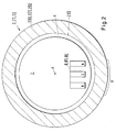
- Fig. 2 shows in more detail a first embodiment of an evaporation cathode 2, 21, 22 with permanent magnetic field source 8, 81, 82.
- the evaporation cathode 2, 21, 22 of the Fig. 2 which may be, for example, a sputtering cathode 21 or an arc cathode 22, carries on an outer cylindrical surface 210 the target material 200, 201, 202 with which a substrate S is to be coated.
- the sputtering cathode 21 can be equipped with a different target material 200, 201 than the arc cathode 22, which comprises a different target material 200, 202, so that, in particular, complicated combination layer systems can be produced.
- the sputtering cathode 21 and the arc cathode 22 may also be equipped with the same target material 200, 201, 202.
- a cooling gap K is provided through which a coolant, eg cooling water in the Operating state is circulated, which cools the evaporation cathode 2, 21, 22 in the operating state.
- the target material 200, 201, 202 is evaporated substantially in the region B, since the magnetic field generated by the magnetic field source 8, 81, 82 concentrates the arc or the sputtering ions for evaporation of the target material 200, 201, 202 on the region B.
- the evaporation cathode 2, 21, 22 rotates in the operating state about the longitudinal axis A, while the magnetic field source does not rotate, so that the region B according to this Rotation in the circumferential direction over the surface of the evaporation cathode 2, 21, 22 moves.
- Fig. 3 shows a second embodiment of an evaporation cathode 2, 21, 22 with permanent magnetic field source 8, 81, 82.
- the example of Fig. 3 is different from the one of Fig. 2 in that an additional magnetic field source 8, 81, 82 is provided.
- an additional magnetic field source 8, 81, 82 is provided.
- the magnetic field source 8, 81, 82 can also be realized, for example, advantageously by electromagnets 8, 81, 82.
- Two specific embodiments show the Fig. 4 with a central coil winding 800 and the Fig. 5 with two separate outer coil windings 800. It is understood that depending on the configuration and arrangement of the coil windings 800 depending on the requirements special magnetic field geometries can be generated.
Landscapes
- Chemical & Material Sciences (AREA)
- Engineering & Computer Science (AREA)
- Physics & Mathematics (AREA)
- Plasma & Fusion (AREA)
- Analytical Chemistry (AREA)
- Chemical Kinetics & Catalysis (AREA)
- Materials Engineering (AREA)
- Mechanical Engineering (AREA)
- Metallurgy (AREA)
- Organic Chemistry (AREA)
- Physical Vapour Deposition (AREA)
Priority Applications (1)
| Application Number | Priority Date | Filing Date | Title |
|---|---|---|---|
| EP09161905.6A EP2159821B1 (fr) | 2008-09-02 | 2009-06-04 | Dispositif de revêtement destiné au revêtement d'un substrat et procédé de revêtement d'un substrat |
Applications Claiming Priority (2)
| Application Number | Priority Date | Filing Date | Title |
|---|---|---|---|
| EP08163508 | 2008-09-02 | ||
| EP09161905.6A EP2159821B1 (fr) | 2008-09-02 | 2009-06-04 | Dispositif de revêtement destiné au revêtement d'un substrat et procédé de revêtement d'un substrat |
Publications (3)
| Publication Number | Publication Date |
|---|---|
| EP2159821A2 true EP2159821A2 (fr) | 2010-03-03 |
| EP2159821A3 EP2159821A3 (fr) | 2010-09-22 |
| EP2159821B1 EP2159821B1 (fr) | 2020-01-15 |
Family
ID=40260861
Family Applications (1)
| Application Number | Title | Priority Date | Filing Date |
|---|---|---|---|
| EP09161905.6A Active EP2159821B1 (fr) | 2008-09-02 | 2009-06-04 | Dispositif de revêtement destiné au revêtement d'un substrat et procédé de revêtement d'un substrat |
Country Status (4)
| Country | Link |
|---|---|
| US (2) | US20100051445A1 (fr) |
| EP (1) | EP2159821B1 (fr) |
| JP (2) | JP2010059544A (fr) |
| ES (1) | ES2774167T3 (fr) |
Cited By (4)
| Publication number | Priority date | Publication date | Assignee | Title |
|---|---|---|---|---|
| EP2516693A1 (fr) * | 2009-11-23 | 2012-10-31 | SHM, s.r.o. | Procédé de création de couches de dépôt physique en phase vapeur à l'aide d'une cathode cylindrique tournante, et appareil pour la mise en uvre de ce procédé |
| EP2746424A1 (fr) | 2012-12-21 | 2014-06-25 | Sulzer Metaplas GmbH | Source d'évaporation |
| EP2778253A1 (fr) | 2013-02-26 | 2014-09-17 | Sulzer Metaplas GmbH | Source d'évaporation cylindrique |
| CN110892502A (zh) * | 2017-06-01 | 2020-03-17 | 欧瑞康表面处理解决方案股份公司普费菲孔 | 用于脆性材料的安全经济蒸发的靶组件 |
Families Citing this family (10)
| Publication number | Priority date | Publication date | Assignee | Title |
|---|---|---|---|---|
| US8374633B2 (en) | 2009-10-05 | 2013-02-12 | Motorola Mobility Llc | Muting indication to enable improved time difference of arrival measurements |
| CA2791288A1 (fr) * | 2010-03-31 | 2011-10-06 | Mustang Vacuum Systems, Llc | Dispositif a cathode de pulverisation par magnetron tournant cylindrique et procede de depot d'un materiau utilisant des emissions radiofrequences |
| EP2521159A1 (fr) * | 2011-05-06 | 2012-11-07 | Pivot a.s. | Appareil décharge luminescente et procédé de cathodes à arc à rotation latérale |
| PL2540858T3 (pl) * | 2011-06-30 | 2015-06-30 | Lamina Tech Sa | Osadzania za pomocą łuku katodowego |
| EP2602354A1 (fr) * | 2011-12-05 | 2013-06-12 | Pivot a.s. | Appareil et procédé de dépôt sous vide par arc cathodique filtré et procédé |
| WO2016005476A1 (fr) * | 2014-07-09 | 2016-01-14 | Soleras Advanced Coatings Bvba | Dispositif de pulvérisation à cible mobile |
| EP2966192A1 (fr) * | 2014-07-09 | 2016-01-13 | Soleras Advanced Coatings bvba | Dispositif de pulvérisation avec cibles mobiles |
| CN105018883A (zh) * | 2015-07-17 | 2015-11-04 | 益固(上海)真空设备科技有限公司 | 一种真空镀膜设备 |
| KR101924143B1 (ko) * | 2017-03-31 | 2018-11-30 | 한국알박(주) | 자석 구조체, 자석 유닛 및 이를 포함하는 마그네트론 스퍼터링 장치 |
| JP2023024280A (ja) * | 2021-08-04 | 2023-02-16 | エフ・ハー・エル・アンラーゲンバウ・ゲゼルシャフト・ミト・ベシュレンクテル・ハフツング | 多連スパッタリングターゲット |
Citations (1)
| Publication number | Priority date | Publication date | Assignee | Title |
|---|---|---|---|---|
| WO1990002216A1 (fr) | 1988-08-25 | 1990-03-08 | Vac-Tec Systems, Inc. | Appareil et procede de revetement double par deposition en phase gazeuse par procede physique |
Family Cites Families (21)
| Publication number | Priority date | Publication date | Assignee | Title |
|---|---|---|---|---|
| DE4017111C2 (de) * | 1990-05-28 | 1998-01-29 | Hauzer Holding | Lichtbogen-Magnetron-Vorrichtung |
| US5306407A (en) * | 1989-06-27 | 1994-04-26 | Hauzer Holding Bv | Method and apparatus for coating substrates |
| JPH1129866A (ja) * | 1997-07-11 | 1999-02-02 | Fujitsu Ltd | スパッタ装置 |
| WO1999054911A1 (fr) * | 1998-04-16 | 1999-10-28 | Sinvaco N.V. | Dispositif de commande d'erosion et de pulverisation de cible dans un magnetron |
| CZ296094B6 (cs) * | 2000-12-18 | 2006-01-11 | Shm, S. R. O. | Zarízení pro odparování materiálu k povlakování predmetu |
| AUPR353601A0 (en) * | 2001-03-05 | 2001-03-29 | Commonwealth Scientific And Industrial Research Organisation | Deposition process |
| ATE277204T1 (de) * | 2001-03-27 | 2004-10-15 | Fundacion Tekniker | Lichtbogenverdampfer mit kraftvoller magnetführung für targets mit grosser oberfläche |
| DE10155120A1 (de) * | 2001-11-09 | 2003-05-28 | Ernst Klinkenberg | Verfahren und Vorrichtung zur Beschichtung eines Substrats durch eine verteilt initiierte gepulste kathodische Bogenerosion einer Opferelektrode |
| JP4034563B2 (ja) * | 2001-12-27 | 2008-01-16 | 株式会社神戸製鋼所 | 真空アーク蒸発源 |
| DK1357577T3 (da) * | 2002-04-22 | 2008-06-02 | Pivot A S | Buecoatingfremgangsmåde med roterende katoder |
| SG118232A1 (en) * | 2004-02-27 | 2006-06-27 | Superiorcoat Private Ltd | Cathodic arc coating apparatus |
| CN100577874C (zh) * | 2004-04-19 | 2010-01-06 | 皮沃特公司 | 硬质耐磨的氮化铝基涂层 |
| EP1609882A1 (fr) * | 2004-06-24 | 2005-12-28 | METAPLAS IONON Oberflächenveredelungstechnik GmbH | Système et methode de dépot par pulverisation cathodique |
| EP1774563A1 (fr) * | 2004-07-01 | 2007-04-18 | Cardinal CG Company | Cible cylindrique a aimant oscillant pour pulverisation cathodique magnetron |
| DE102006004394B4 (de) * | 2005-02-16 | 2011-01-13 | Kabushiki Kaisha Kobe Seiko Sho (Kobe Steel, Ltd.), Kobe-shi | Hartfilm, Mehrschichthartfilm und Herstellungsverfahren dafür |
| US20060207871A1 (en) * | 2005-03-16 | 2006-09-21 | Gennady Yumshtyk | Sputtering devices and methods |
| DE502005005634D1 (de) * | 2005-09-15 | 2008-11-20 | Applied Materials Gmbh & Co Kg | Beschichtungsanlage und Verfahren zum Betrieb einer Beschichtungsanlage |
| ATE425548T1 (de) * | 2005-12-22 | 2009-03-15 | Applied Materials Gmbh & Co Kg | Zerstäubungsvorrichtung mit einer rohrkathode und verfahren zum betreiben dieser zerstäubungsvorrichtung |
| US7879203B2 (en) * | 2006-12-11 | 2011-02-01 | General Electric Company | Method and apparatus for cathodic arc ion plasma deposition |
| CN101368260A (zh) * | 2007-09-14 | 2009-02-18 | 山特维克知识产权股份有限公司 | 用于在基底上沉积涂层的方法和设备 |
| US9175383B2 (en) * | 2008-01-16 | 2015-11-03 | Applied Materials, Inc. | Double-coating device with one process chamber |
-
2009
- 2009-06-04 EP EP09161905.6A patent/EP2159821B1/fr active Active
- 2009-06-04 ES ES09161905T patent/ES2774167T3/es active Active
- 2009-08-10 JP JP2009185373A patent/JP2010059544A/ja active Pending
- 2009-08-31 US US12/550,600 patent/US20100051445A1/en not_active Abandoned
-
2014
- 2014-09-16 JP JP2014187763A patent/JP6101238B2/ja active Active
- 2014-09-26 US US14/497,665 patent/US20150008118A1/en not_active Abandoned
Patent Citations (1)
| Publication number | Priority date | Publication date | Assignee | Title |
|---|---|---|---|---|
| WO1990002216A1 (fr) | 1988-08-25 | 1990-03-08 | Vac-Tec Systems, Inc. | Appareil et procede de revetement double par deposition en phase gazeuse par procede physique |
Cited By (6)
| Publication number | Priority date | Publication date | Assignee | Title |
|---|---|---|---|---|
| EP2516693A1 (fr) * | 2009-11-23 | 2012-10-31 | SHM, s.r.o. | Procédé de création de couches de dépôt physique en phase vapeur à l'aide d'une cathode cylindrique tournante, et appareil pour la mise en uvre de ce procédé |
| EP2746424A1 (fr) | 2012-12-21 | 2014-06-25 | Sulzer Metaplas GmbH | Source d'évaporation |
| US9728382B2 (en) | 2012-12-21 | 2017-08-08 | Oerlikon Surface Solutions Ag, Pfaeffikon | Evaporation source |
| EP2778253A1 (fr) | 2013-02-26 | 2014-09-17 | Sulzer Metaplas GmbH | Source d'évaporation cylindrique |
| US10811239B2 (en) | 2013-02-26 | 2020-10-20 | Oerlikon Surface Solutions Ag, Pfäffikon | Cylindrical evaporation source |
| CN110892502A (zh) * | 2017-06-01 | 2020-03-17 | 欧瑞康表面处理解决方案股份公司普费菲孔 | 用于脆性材料的安全经济蒸发的靶组件 |
Also Published As
| Publication number | Publication date |
|---|---|
| JP2014231644A (ja) | 2014-12-11 |
| JP2010059544A (ja) | 2010-03-18 |
| US20100051445A1 (en) | 2010-03-04 |
| US20150008118A1 (en) | 2015-01-08 |
| ES2774167T3 (es) | 2020-07-17 |
| EP2159821A3 (fr) | 2010-09-22 |
| EP2159821B1 (fr) | 2020-01-15 |
| JP6101238B2 (ja) | 2017-03-22 |
Similar Documents
| Publication | Publication Date | Title |
|---|---|---|
| EP2159821B1 (fr) | Dispositif de revêtement destiné au revêtement d'un substrat et procédé de revêtement d'un substrat | |
| DE3700633C2 (de) | Verfahren und Vorrichtung zum schonenden Beschichten elektrisch leitender Gegenstände mittels Plasma | |
| EP0306612B1 (fr) | Procédé de déposition de couches sur des substrats | |
| EP2720248B1 (fr) | Source de vaporisation d'arcs électriques à vide ainsi que chambre de vaporisation d'arcs électriques dotée d'une source de vaporisation d'arcs électriques à vide | |
| EP2778253B1 (fr) | Source d'évaporation cylindrique | |
| EP2041331B1 (fr) | Procédé pour le dépôt de couches électriquement isolantes | |
| DE69329161T2 (de) | Verbesserungen von Verfahren der physikalischen Dampfphasen-Abscheidung | |
| DE69009078T2 (de) | System und Methode zur Ablagerung von dünnen Filmen im Vakuum. | |
| DE3206882A1 (de) | Verfahren und vorrichtung zum verdampfen von material unter vakuum | |
| WO2007131944A2 (fr) | Source d'arc et ensemble aimants | |
| DE4042337C1 (en) | Controlling degree of ionisation of vapour for surface coating - by preventing straight line current flow between hot anode target surface and cold cathode by using movable wall between them | |
| EP1576641B1 (fr) | Source d'arc sous vide comprenant un dispositif de production de champ magnetique | |
| EP0438627B1 (fr) | Dispositif d'évaporation par décharge d'arc ayant plusieurs creusets d'évaporation | |
| EP2030490B1 (fr) | Procédé et dispositif de génération de plasma et leur utilisation | |
| DE3901401A1 (de) | Verfahren zur steuerung einer vakuum-lichtbogenentladung | |
| EP2789006A1 (fr) | Procédé de pulvérisation cathodique réactive | |
| EP0666335A1 (fr) | Méthode de conduite d'opération d'un évaporateur à arc sous vide et sa source de courant | |
| DE4203371C1 (fr) | ||
| DE102008032256B4 (de) | Vorrichtung und Verfahren zum Abscheiden aus der Dampfphase mit Sputterverstärkung | |
| EP2746424B1 (fr) | Source d'évaporation | |
| DE10155120A1 (de) | Verfahren und Vorrichtung zur Beschichtung eines Substrats durch eine verteilt initiierte gepulste kathodische Bogenerosion einer Opferelektrode | |
| EP1473382A1 (fr) | Procédé et dispositif de déposition d'une couche activée par plasma par pulvérisation magnétron | |
| DE102007041327B4 (de) | Verfahren und Vorrichtung zur Herstellung von Nanopulver | |
| DE102010061487A1 (de) | Verfahren zum Behandeln und/oder Beschichten von Oberflächen | |
| EP3583619B1 (fr) | Évaporation par arc cathodique avec enlèvement de matière à la cathode prédéfini |
Legal Events
| Date | Code | Title | Description |
|---|---|---|---|
| PUAI | Public reference made under article 153(3) epc to a published international application that has entered the european phase |
Free format text: ORIGINAL CODE: 0009012 |
|
| AK | Designated contracting states |
Kind code of ref document: A2 Designated state(s): AT BE BG CH CY CZ DE DK EE ES FI FR GB GR HR HU IE IS IT LI LT LU LV MC MK MT NL NO PL PT RO SE SI SK TR |
|
| PUAL | Search report despatched |
Free format text: ORIGINAL CODE: 0009013 |
|
| AK | Designated contracting states |
Kind code of ref document: A3 Designated state(s): AT BE BG CH CY CZ DE DK EE ES FI FR GB GR HR HU IE IS IT LI LT LU LV MC MK MT NL NO PL PT RO SE SI SK TR |
|
| 17P | Request for examination filed |
Effective date: 20110322 |
|
| 17Q | First examination report despatched |
Effective date: 20160518 |
|
| STAA | Information on the status of an ep patent application or granted ep patent |
Free format text: STATUS: EXAMINATION IS IN PROGRESS |
|
| GRAP | Despatch of communication of intention to grant a patent |
Free format text: ORIGINAL CODE: EPIDOSNIGR1 |
|
| STAA | Information on the status of an ep patent application or granted ep patent |
Free format text: STATUS: GRANT OF PATENT IS INTENDED |
|
| INTG | Intention to grant announced |
Effective date: 20190917 |
|
| RAP1 | Party data changed (applicant data changed or rights of an application transferred) |
Owner name: OERLIKON SURFACE SOLUTIONS AG, PFAEFFIKON |
|
| GRAS | Grant fee paid |
Free format text: ORIGINAL CODE: EPIDOSNIGR3 |
|
| GRAA | (expected) grant |
Free format text: ORIGINAL CODE: 0009210 |
|
| STAA | Information on the status of an ep patent application or granted ep patent |
Free format text: STATUS: THE PATENT HAS BEEN GRANTED |
|
| AK | Designated contracting states |
Kind code of ref document: B1 Designated state(s): AT BE BG CH CY CZ DE DK EE ES FI FR GB GR HR HU IE IS IT LI LT LU LV MC MK MT NL NO PL PT RO SE SI SK TR |
|
| REG | Reference to a national code |
Ref country code: CH Ref legal event code: EP Ref country code: GB Ref legal event code: FG4D Free format text: NOT ENGLISH |
|
| REG | Reference to a national code |
Ref country code: IE Ref legal event code: FG4D Free format text: LANGUAGE OF EP DOCUMENT: GERMAN |
|
| REG | Reference to a national code |
Ref country code: DE Ref legal event code: R096 Ref document number: 502009016094 Country of ref document: DE |
|
| REG | Reference to a national code |
Ref country code: AT Ref legal event code: REF Ref document number: 1225888 Country of ref document: AT Kind code of ref document: T Effective date: 20200215 |
|
| REG | Reference to a national code |
Ref country code: FI Ref legal event code: FGE |
|
| REG | Reference to a national code |
Ref country code: SE Ref legal event code: TRGR |
|
| REG | Reference to a national code |
Ref country code: NL Ref legal event code: FP |
|
| REG | Reference to a national code |
Ref country code: SK Ref legal event code: T3 Ref document number: E 33438 Country of ref document: SK |
|
| REG | Reference to a national code |
Ref country code: ES Ref legal event code: FG2A Ref document number: 2774167 Country of ref document: ES Kind code of ref document: T3 Effective date: 20200717 |
|
| REG | Reference to a national code |
Ref country code: LT Ref legal event code: MG4D |
|
| PG25 | Lapsed in a contracting state [announced via postgrant information from national office to epo] |
Ref country code: PT Free format text: LAPSE BECAUSE OF FAILURE TO SUBMIT A TRANSLATION OF THE DESCRIPTION OR TO PAY THE FEE WITHIN THE PRESCRIBED TIME-LIMIT Effective date: 20200607 Ref country code: NO Free format text: LAPSE BECAUSE OF FAILURE TO SUBMIT A TRANSLATION OF THE DESCRIPTION OR TO PAY THE FEE WITHIN THE PRESCRIBED TIME-LIMIT Effective date: 20200415 |
|
| PG25 | Lapsed in a contracting state [announced via postgrant information from national office to epo] |
Ref country code: HR Free format text: LAPSE BECAUSE OF FAILURE TO SUBMIT A TRANSLATION OF THE DESCRIPTION OR TO PAY THE FEE WITHIN THE PRESCRIBED TIME-LIMIT Effective date: 20200115 Ref country code: GR Free format text: LAPSE BECAUSE OF FAILURE TO SUBMIT A TRANSLATION OF THE DESCRIPTION OR TO PAY THE FEE WITHIN THE PRESCRIBED TIME-LIMIT Effective date: 20200416 Ref country code: LV Free format text: LAPSE BECAUSE OF FAILURE TO SUBMIT A TRANSLATION OF THE DESCRIPTION OR TO PAY THE FEE WITHIN THE PRESCRIBED TIME-LIMIT Effective date: 20200115 Ref country code: BG Free format text: LAPSE BECAUSE OF FAILURE TO SUBMIT A TRANSLATION OF THE DESCRIPTION OR TO PAY THE FEE WITHIN THE PRESCRIBED TIME-LIMIT Effective date: 20200415 Ref country code: IS Free format text: LAPSE BECAUSE OF FAILURE TO SUBMIT A TRANSLATION OF THE DESCRIPTION OR TO PAY THE FEE WITHIN THE PRESCRIBED TIME-LIMIT Effective date: 20200515 |
|
| REG | Reference to a national code |
Ref country code: DE Ref legal event code: R097 Ref document number: 502009016094 Country of ref document: DE |
|
| PG25 | Lapsed in a contracting state [announced via postgrant information from national office to epo] |
Ref country code: LT Free format text: LAPSE BECAUSE OF FAILURE TO SUBMIT A TRANSLATION OF THE DESCRIPTION OR TO PAY THE FEE WITHIN THE PRESCRIBED TIME-LIMIT Effective date: 20200115 Ref country code: EE Free format text: LAPSE BECAUSE OF FAILURE TO SUBMIT A TRANSLATION OF THE DESCRIPTION OR TO PAY THE FEE WITHIN THE PRESCRIBED TIME-LIMIT Effective date: 20200115 Ref country code: DK Free format text: LAPSE BECAUSE OF FAILURE TO SUBMIT A TRANSLATION OF THE DESCRIPTION OR TO PAY THE FEE WITHIN THE PRESCRIBED TIME-LIMIT Effective date: 20200115 Ref country code: RO Free format text: LAPSE BECAUSE OF FAILURE TO SUBMIT A TRANSLATION OF THE DESCRIPTION OR TO PAY THE FEE WITHIN THE PRESCRIBED TIME-LIMIT Effective date: 20200115 |
|
| PLBE | No opposition filed within time limit |
Free format text: ORIGINAL CODE: 0009261 |
|
| STAA | Information on the status of an ep patent application or granted ep patent |
Free format text: STATUS: NO OPPOSITION FILED WITHIN TIME LIMIT |
|
| 26N | No opposition filed |
Effective date: 20201016 |
|
| PG25 | Lapsed in a contracting state [announced via postgrant information from national office to epo] |
Ref country code: MC Free format text: LAPSE BECAUSE OF FAILURE TO SUBMIT A TRANSLATION OF THE DESCRIPTION OR TO PAY THE FEE WITHIN THE PRESCRIBED TIME-LIMIT Effective date: 20200115 |
|
| PG25 | Lapsed in a contracting state [announced via postgrant information from national office to epo] |
Ref country code: PL Free format text: LAPSE BECAUSE OF FAILURE TO SUBMIT A TRANSLATION OF THE DESCRIPTION OR TO PAY THE FEE WITHIN THE PRESCRIBED TIME-LIMIT Effective date: 20200115 Ref country code: SI Free format text: LAPSE BECAUSE OF FAILURE TO SUBMIT A TRANSLATION OF THE DESCRIPTION OR TO PAY THE FEE WITHIN THE PRESCRIBED TIME-LIMIT Effective date: 20200115 |
|
| PG25 | Lapsed in a contracting state [announced via postgrant information from national office to epo] |
Ref country code: LU Free format text: LAPSE BECAUSE OF NON-PAYMENT OF DUE FEES Effective date: 20200604 |
|
| REG | Reference to a national code |
Ref country code: BE Ref legal event code: MM Effective date: 20200630 |
|
| PG25 | Lapsed in a contracting state [announced via postgrant information from national office to epo] |
Ref country code: IE Free format text: LAPSE BECAUSE OF NON-PAYMENT OF DUE FEES Effective date: 20200604 |
|
| PG25 | Lapsed in a contracting state [announced via postgrant information from national office to epo] |
Ref country code: BE Free format text: LAPSE BECAUSE OF NON-PAYMENT OF DUE FEES Effective date: 20200630 |
|
| PG25 | Lapsed in a contracting state [announced via postgrant information from national office to epo] |
Ref country code: TR Free format text: LAPSE BECAUSE OF FAILURE TO SUBMIT A TRANSLATION OF THE DESCRIPTION OR TO PAY THE FEE WITHIN THE PRESCRIBED TIME-LIMIT Effective date: 20200115 Ref country code: MT Free format text: LAPSE BECAUSE OF FAILURE TO SUBMIT A TRANSLATION OF THE DESCRIPTION OR TO PAY THE FEE WITHIN THE PRESCRIBED TIME-LIMIT Effective date: 20200115 Ref country code: CY Free format text: LAPSE BECAUSE OF FAILURE TO SUBMIT A TRANSLATION OF THE DESCRIPTION OR TO PAY THE FEE WITHIN THE PRESCRIBED TIME-LIMIT Effective date: 20200115 |
|
| PG25 | Lapsed in a contracting state [announced via postgrant information from national office to epo] |
Ref country code: MK Free format text: LAPSE BECAUSE OF FAILURE TO SUBMIT A TRANSLATION OF THE DESCRIPTION OR TO PAY THE FEE WITHIN THE PRESCRIBED TIME-LIMIT Effective date: 20200115 |
|
| PGFP | Annual fee paid to national office [announced via postgrant information from national office to epo] |
Ref country code: FI Payment date: 20250624 Year of fee payment: 17 |
|
| PGFP | Annual fee paid to national office [announced via postgrant information from national office to epo] |
Ref country code: DE Payment date: 20250626 Year of fee payment: 17 |
|
| PGFP | Annual fee paid to national office [announced via postgrant information from national office to epo] |
Ref country code: GB Payment date: 20250617 Year of fee payment: 17 |
|
| PGFP | Annual fee paid to national office [announced via postgrant information from national office to epo] |
Ref country code: NL Payment date: 20250624 Year of fee payment: 17 |
|
| PGFP | Annual fee paid to national office [announced via postgrant information from national office to epo] |
Ref country code: FR Payment date: 20250624 Year of fee payment: 17 |
|
| PGFP | Annual fee paid to national office [announced via postgrant information from national office to epo] |
Ref country code: AT Payment date: 20250617 Year of fee payment: 17 |
|
| PGFP | Annual fee paid to national office [announced via postgrant information from national office to epo] |
Ref country code: SK Payment date: 20250519 Year of fee payment: 17 |
|
| PGFP | Annual fee paid to national office [announced via postgrant information from national office to epo] |
Ref country code: CZ Payment date: 20250520 Year of fee payment: 17 |
|
| PGFP | Annual fee paid to national office [announced via postgrant information from national office to epo] |
Ref country code: SE Payment date: 20250619 Year of fee payment: 17 |
|
| PGFP | Annual fee paid to national office [announced via postgrant information from national office to epo] |
Ref country code: ES Payment date: 20250710 Year of fee payment: 17 |
|
| PGFP | Annual fee paid to national office [announced via postgrant information from national office to epo] |
Ref country code: IT Payment date: 20250623 Year of fee payment: 17 |
|
| PGFP | Annual fee paid to national office [announced via postgrant information from national office to epo] |
Ref country code: CH Payment date: 20250701 Year of fee payment: 17 |