EP2160992B1 - Appareil électrochirurgical avec récupération d'énergie à haute vitesse - Google Patents
Appareil électrochirurgical avec récupération d'énergie à haute vitesse Download PDFInfo
- Publication number
- EP2160992B1 EP2160992B1 EP09169588.2A EP09169588A EP2160992B1 EP 2160992 B1 EP2160992 B1 EP 2160992B1 EP 09169588 A EP09169588 A EP 09169588A EP 2160992 B1 EP2160992 B1 EP 2160992B1
- Authority
- EP
- European Patent Office
- Prior art keywords
- circuit
- output
- switching component
- discharging
- controlling
- Prior art date
- Legal status (The legal status is an assumption and is not a legal conclusion. Google has not performed a legal analysis and makes no representation as to the accuracy of the status listed.)
- Not-in-force
Links
Images


Classifications
-
- A—HUMAN NECESSITIES
- A61—MEDICAL OR VETERINARY SCIENCE; HYGIENE
- A61B—DIAGNOSIS; SURGERY; IDENTIFICATION
- A61B18/00—Surgical instruments, devices or methods for transferring non-mechanical forms of energy to or from the body
- A61B18/04—Surgical instruments, devices or methods for transferring non-mechanical forms of energy to or from the body by heating
- A61B18/12—Surgical instruments, devices or methods for transferring non-mechanical forms of energy to or from the body by heating by passing a current through the tissue to be heated, e.g. high-frequency current
- A61B18/1206—Generators therefor
-
- A—HUMAN NECESSITIES
- A61—MEDICAL OR VETERINARY SCIENCE; HYGIENE
- A61B—DIAGNOSIS; SURGERY; IDENTIFICATION
- A61B18/00—Surgical instruments, devices or methods for transferring non-mechanical forms of energy to or from the body
- A61B18/04—Surgical instruments, devices or methods for transferring non-mechanical forms of energy to or from the body by heating
- A61B18/12—Surgical instruments, devices or methods for transferring non-mechanical forms of energy to or from the body by heating by passing a current through the tissue to be heated, e.g. high-frequency current
- A61B18/1206—Generators therefor
- A61B18/1233—Generators therefor with circuits for assuring patient safety
-
- A—HUMAN NECESSITIES
- A61—MEDICAL OR VETERINARY SCIENCE; HYGIENE
- A61B—DIAGNOSIS; SURGERY; IDENTIFICATION
- A61B18/00—Surgical instruments, devices or methods for transferring non-mechanical forms of energy to or from the body
- A61B18/04—Surgical instruments, devices or methods for transferring non-mechanical forms of energy to or from the body by heating
- A61B18/12—Surgical instruments, devices or methods for transferring non-mechanical forms of energy to or from the body by heating by passing a current through the tissue to be heated, e.g. high-frequency current
- A61B18/14—Probes or electrodes therefor
- A61B18/1442—Probes having pivoting end effectors, e.g. forceps
- A61B18/1445—Probes having pivoting end effectors, e.g. forceps at the distal end of a shaft, e.g. forceps or scissors at the end of a rigid rod
-
- A—HUMAN NECESSITIES
- A61—MEDICAL OR VETERINARY SCIENCE; HYGIENE
- A61B—DIAGNOSIS; SURGERY; IDENTIFICATION
- A61B18/00—Surgical instruments, devices or methods for transferring non-mechanical forms of energy to or from the body
- A61B2018/00315—Surgical instruments, devices or methods for transferring non-mechanical forms of energy to or from the body for treatment of particular body parts
- A61B2018/00345—Vascular system
-
- A—HUMAN NECESSITIES
- A61—MEDICAL OR VETERINARY SCIENCE; HYGIENE
- A61B—DIAGNOSIS; SURGERY; IDENTIFICATION
- A61B18/00—Surgical instruments, devices or methods for transferring non-mechanical forms of energy to or from the body
- A61B2018/00315—Surgical instruments, devices or methods for transferring non-mechanical forms of energy to or from the body for treatment of particular body parts
- A61B2018/00345—Vascular system
- A61B2018/00404—Blood vessels other than those in or around the heart
-
- A—HUMAN NECESSITIES
- A61—MEDICAL OR VETERINARY SCIENCE; HYGIENE
- A61B—DIAGNOSIS; SURGERY; IDENTIFICATION
- A61B18/00—Surgical instruments, devices or methods for transferring non-mechanical forms of energy to or from the body
- A61B2018/00571—Surgical instruments, devices or methods for transferring non-mechanical forms of energy to or from the body for achieving a particular surgical effect
- A61B2018/00619—Welding
-
- A—HUMAN NECESSITIES
- A61—MEDICAL OR VETERINARY SCIENCE; HYGIENE
- A61B—DIAGNOSIS; SURGERY; IDENTIFICATION
- A61B18/00—Surgical instruments, devices or methods for transferring non-mechanical forms of energy to or from the body
- A61B2018/00571—Surgical instruments, devices or methods for transferring non-mechanical forms of energy to or from the body for achieving a particular surgical effect
- A61B2018/0063—Sealing
-
- A—HUMAN NECESSITIES
- A61—MEDICAL OR VETERINARY SCIENCE; HYGIENE
- A61B—DIAGNOSIS; SURGERY; IDENTIFICATION
- A61B18/00—Surgical instruments, devices or methods for transferring non-mechanical forms of energy to or from the body
- A61B2018/00636—Sensing and controlling the application of energy
- A61B2018/00696—Controlled or regulated parameters
- A61B2018/00702—Power or energy
-
- A—HUMAN NECESSITIES
- A61—MEDICAL OR VETERINARY SCIENCE; HYGIENE
- A61B—DIAGNOSIS; SURGERY; IDENTIFICATION
- A61B18/00—Surgical instruments, devices or methods for transferring non-mechanical forms of energy to or from the body
- A61B2018/00636—Sensing and controlling the application of energy
- A61B2018/00773—Sensed parameters
- A61B2018/00875—Resistance or impedance
-
- A—HUMAN NECESSITIES
- A61—MEDICAL OR VETERINARY SCIENCE; HYGIENE
- A61B—DIAGNOSIS; SURGERY; IDENTIFICATION
- A61B18/00—Surgical instruments, devices or methods for transferring non-mechanical forms of energy to or from the body
- A61B2018/00636—Sensing and controlling the application of energy
- A61B2018/00773—Sensed parameters
- A61B2018/00892—Voltage
Definitions
- the present disclosure relates to an electrosurgical system and method and, more particularly, to an electrosurgical generator configured to dynamically control energy output.
- Electrosurgery involves application of high radio frequency electrical current to a surgical site to cut, seal, ablate, or coagulate tissue.
- a source or active electrode delivers radio frequency energy from the electrosurgical generator to the tissue and a return electrode carries the current back to the generator.
- the source electrode is typically part of a surgical instrument held by the surgeon and applied to the tissue to be treated.
- a patient return electrode is placed remotely from the active electrode to carry the current back to the generator.
- a hand-held instrument typically carries two electrodes, e.g., electrosurgical forceps.
- One of the electrodes of the hand-held instrument functions as the active electrode and the other as the return electrode.
- the return electrode is placed in close proximity to the active (i.e., current supplying) electrode such that an electrical circuit is formed between the two electrodes. In this manner, the applied electrical current is limited to the body tissue positioned between the two electrodes.
- Conventional electrosurgical generators include a high voltage direct current power supply connected to a radio frequency (RF) output stage that converts DC energy generated by the power supply into RF energy.
- the power supply includes an output filter which substantially eliminates undesirable frequencies (e.g., noise) from the DC energy and stores large amounts of energy. Rapid tissue desiccation during the application of RF energy creates a potential for patient burn hazards due to excess energy dosage at the tissue site when the power source fails to rapidly alter the supplied energy dosage in response with dynamic changes in tissue impedance. Rising tissue impedance levels caused by desiccation unload the energy source and sustain the energy delivered to the tissue due to the large amount of stored energy in the output filter.
- EP 1 776 929 A1 is concerned with a circuit for reducing stored energy in an electrosurgical generator.
- a circuit for controlling the discharging of stored energy in an electrosurgical generator is provided according to claim 1.
- a circuit for controlling the discharging of stored energy in an electrosurgical generator is provided according to claim 10.
- the present disclosure also provides a method for controlling the discharging of stored energy in an electrosurgical generator.
- the method includes applying energy stored in an output of a power supply to tissue.
- the method also includes generating at least one control signal based on at least one of a sensed tissue property and a sensed energy delivery property, (i.e. power, voltage, current, time etc.).
- the method also includes generating an error signal based on a comparison between the at least one control signal and the energy stored in the output.
- the method also includes discharging the stored energy to an inductive load in parallel with the output of the power supply based upon the comparison between the energy stored in the output and the control signal.
- an electrosurgical generator including a power supply configured to rapidly re-direct stored output energy through inductive energy transfer utilizing a controlled switching circuit to regulate, in real-time, the level of power sourced to the RF energy delivered to tissue during treatment.
- the generator of the present disclosure can control, in real time, the amount of treatment energy applied to tissue through use of a so-called "discharge" circuit.
- the discharge circuit provides a rapid response and time rate control of the electrosurgical energy delivered to tissue by discharging energy stored in an output filter of the power supply into an inductive load based on a feedback signal generated by the controller.
- the feedback signal may be based on a sensed tissue property (e.g., impedance) and/or an energy property (e.g., voltage, output energy level, etc.). This control provides for more accurate application of target treatment energy levels to treat tissue.
- the generator according to the present disclosure can perform monopolar and bipolar electrosurgical procedures, including vessel sealing procedures.
- the generator may include a plurality of outputs for interfacing with various electrosurgical instruments (e.g., a monopolar active electrode, return electrode, bipolar electrosurgical forceps, footswitch, etc.).
- various electrosurgical instruments e.g., a monopolar active electrode, return electrode, bipolar electrosurgical forceps, footswitch, etc.
- the generator includes electronic circuitry configured for generating radio frequency power specifically suited for various electrosurgical modes (e.g., cutting, blending, division, etc.) and procedures (e.g., monopolar, bipolar, vessel sealing, ablation).
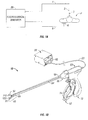
- Fig. 1A is a schematic illustration of a monopolar electrosurgical system according to one embodiment of the present disclosure.
- the system includes a monopolar electrosurgical instrument 2 including one or more active electrodes 3, which can be electrosurgical cutting probes, ablation electrode(s), etc.
- Electrosurgical RF energy is supplied to the instrument 2 by a generator 20 via a supply line 4, which is connected to an active terminal 30 ( Fig. 2 ) of the generator 20, allowing the instrument 2 to coagulate, ablate and/or otherwise treat tissue.
- the energy is returned to the generator 20 through a return electrode 6 via a return line 8 at a return terminal 32 ( Fig. 2 ) of the generator 20.
- the active terminal 30 and the return terminal 32 are connectors configured to interface with plugs (not explicitly shown) of the instrument 2 and the return electrode 6, which are disposed at the ends of the supply line 4 and the return line 8, respectively.
- Fig. 1B shows a bipolar electrosurgical system according to the present disclosure that includes an electrosurgical forceps 10 having opposing jaw members 50 and 55.
- the forceps 10 includes a shaft member 64 having an end effector assembly 40 disposed at the distal end thereof.
- the end effector assembly 40 includes two jaw members 50 and 55 movable from a first position wherein the jaw members 50 and 55 are spaced relative to another to a closed position wherein the jaw members 50 and 55 cooperate to grasp tissue therebetween.
- Each of the jaw members 50 and 55 includes an electrically conductive sealing plate 112 and 122, respectively, connected to the generator 20 that communicates electrosurgical energy through the tissue held therebetween.
- Electrosurgical RF energy is supplied to the forceps 10 by generator 20 via a supply line connected to the active electrode and returned through a return line connected to the return electrode.
- Forceps 10 generally includes a housing 60 and a handle assembly 74 that includes moveable handle 62 and handle 72 which is integral with the housing 60. Handle 62 is moveable relative to handle 72 to actuate the end effector assembly 40 to grasp and treat tissue.
- the forceps 10 also includes shaft 64 that has a distal end 68 that mechanically engages the end effector assembly 40 and a proximal end 69 that mechanically engages the housing 60 proximate a rotating assembly 80 disposed at a distal end of the housing 60.
- the generator 20 includes suitable input controls (e.g., buttons, activators, switches, touch screen, etc.) for controlling the generator 20.
- the generator 20 includes one or more display screens for providing the surgeon with variety of output information (e.g., intensity settings, treatment complete indicators, etc.).
- the controls allow the surgeon to adjust power of the RF energy, waveform, and other parameters to achieve the desired waveform suitable for a particular task (e.g., coagulating, tissue sealing, division with hemostasis, etc.).
- the forceps 10 may include a plurality of input controls which may be redundant with certain input controls of the generator 20. Placing the input controls at the forceps 10 allows for easier and faster modification of RF energy parameters during the surgical procedure without requiring interaction with the generator 20.
- Fig. 2 shows a schematic block diagram of the generator 20 having a controller 24, a power supply 27, an RF output stage 28, and a sensor module 22.
- the power supply 27 may provide DC power to the RF output stage 28 which then converts the DC power into RF energy and delivers the RF energy to the forceps 10.
- the controller 24 includes a microprocessor 25 having a memory 26 which may be volatile type memory (e.g., RAM) and/or non-volitile type memory (e.g., flash media, disk media, etc.).
- the microprocessor 25 includes an output port connected to the power supply 27 and/or RF output stage 28 which allows the microprocessor 25 to control the output of the generator 20 according to either open and/or closed control loop schemes.
- a closed loop control scheme generally includes a feedback control loop wherein the sensor module 22 provides feedback to the controller 24 (i.e., information obtained from one or more sensing mechanisms that sense various tissue parameters such as tissue impedance, tissue temperature, output current and/or voltage, etc.).
- the controller 24 then signals the power supply 27, which then adjusts the DC power supplied to the RF output stage, accordingly.
- the controller 24 also receives input signals from the input controls of the generator 20 and/or forceps 10.
- the controller 24 utilizes the input signals to adjust the power output of the generator 20 and/or instructs the generator 20 to perform other control functions.
- the microprocessor 25 is capable of executing software instructions for processing data received by the sensor module 22, and for outputting control signals to the generator 20, accordingly.
- the software instructions, which are executable by the controller 24, are stored in the memory 26 of the controller 24.
- the controller 24 may include analog and/or logic circuitry for processing the sensed values and determining the control signals that are sent to the generator 20, rather than, or in combination with, the microprocessor 25.
- the sensor module 22 may include a plurality of sensors (not explicitly shown) strategically located for sensing various properties or conditions, e.g., tissue impedance, voltage at the tissue site, current at the tissue site, etc.
- the sensors are provided with leads (or wireless) for transmitting information to the controller 24.
- the sensor module 22 may include control circuitry which receives information from multiple sensors, and provides the information and the source of the information (e.g., the particular sensor providing the information) to the controller 24.
- the sensor module 22 may include a real-time voltage sensing system (not explicitly shown) and a real-time current sensing system (not explicitly shown) for sensing real-time values related to applied voltage and current at the surgical site. Additionally, an RMS voltage sensing system (not explicitly shown) and an RMS current sensing system (not explicitly shown) may be included for sensing and deriving RMS values for applied voltage and current at the surgical site.
- the measured or sensed values are further processed, either by circuitry and/or a processor (not explicitly shown) in the sensor module 22 and/or by the controller 24, to determine changes in sensed values and tissue impedance.
- Tissue impedance and changes thereto may be determined by measuring the voltage and/or current across the tissue and then calculating changes thereof over time. The measured and calculated values may be then compared with known or desired voltage and current values associated with various tissue types, procedures, instruments, etc. This may be used to drive electrosurgical output to achieve desired impedance and/or change in impedance values.
- tissue impedance fluctuates in response to adjustments in generator output as well as removal and restoration of liquids (e.g., steam bubbles) from the tissue at the surgical site.
- the controller 24 monitors the tissue impedance and changes in tissue impedance and regulates the output of the generator 20 in response thereto to achieve the desired and optimal electrosurgical effect.
- the control circuit 100 includes a first comparator 110 (e.g., an operational amplifier) having positive and negative input pins +A1 and -A1, respectively.
- Positive input pin +A1 is configured to receive an applied control signal (e.g., a variable DC voltage) from the controller 24 based on any one or more tissue parameters provided by the sensor module 22.
- Negative input pin -A1 is configured to receive a proportionally scaled feedback voltage of the power source output (e.g., connected to the RF output stage 28) to match the applied control signal on input pin +A1, as will be discussed in further detail below.
- the resulting voltage difference at positive and negative input pins +A1 and -A1 causes the first comparator 110 to output an analog error signal (e.g., analog voltage) to drive a pulse modulator ("PM") 115.
- PM may be, for example, a pulse width modulator, a phase shift modulator or any such device known in the art for converting the analog error signal to a digital pulse control signal.
- the PM 115 converts the analog error signal to a digital pulse control signal (e.g., digital voltage) to implement control of a full-bridge power stage 120 by phase shifting the switching of one half-bridge with respect to the other.
- an AC/DC converter 125 converts an available ac signal (e.g., from an ac line voltage) to a dc signal to drive the full-bridge power stage 120, the output of which is, in turn, controlled by the digital pulse control signal to reflect the applied control signal from the controller 24.
- the resulting controlled output of the full-bridge power stage 120 drives an output filter 130 (e.g., a low-pass filter), having an inductor 132 and an output capacitor 134, to generate a DC output voltage V c across the output capacitor 134.
- the resulting output voltage V c is converted to RF energy by the RF output stage 28 and output to the electrosurgical instrument.
- a feedback compensator 140 continuously monitors the output voltage V c (e.g., input to the RF output stage 28) and, in turn, provides a proportionally scaled feedback of the power source output to input pin -A1 of the first comparator 110 to match the applied control signal from the controller 24.
- the ADC 145 includes a second comparator 180 (e.g., an operational amplifier) having negative and positive input pins -A2 and +A2 operably coupled to the positive and negative input pins +A1 and -A2 of the first comparator 110, respectively.
- the input pins -A2 and +A2 of the second comparator 180 continuously monitor the difference between the applied control signal from the controller 24 on positive input pin +A1 and the proportionally scaled feedback of the power source output on negative input pin -A1.
- An inductive load 150 (e.g., an inductor) is connected in parallel with the output filter 130 and in series with the first switching component 160.
- the first switching component 160 is normally off and may be a transistor, such as a field-effect transistor (FET), metal-oxide semiconductor field-effect transistor (MOSFET), insulated gate bipolar transistor (IGBT), relay, or the like.
- FET field-effect transistor
- MOSFET metal-oxide semiconductor field-effect transistor
- IGBT insulated gate bipolar transistor
- a first resistive element 162 is in series with the first switching component 160 and with ground 168, which is known as a source follower circuit. The source follower limits the amount of current that flows through the first resistive element 162, the switching component 160, and the inductor 150.
- the second comparator 180 no longer provides the sufficient drive voltage, resulting in the first switching component 160 to return to the normally off position to interrupt the flow of the conduction current I Q1 through the inductive load 150.
- the interruption of current flow through the inductive load 150 causes the magnetic flux field on the inductive load 150 to collapse due to a back electromagnetic force of voltage thereacross (e.g., a so-called "back EMF effect").
- the back EMF voltage turns on diode 155, connected in shunt with the inductive load 150, to become forward-biased, providing a path for the inductor 150 magnetic flux and conductive current to be reset to zero. In addition this process prevents the back EMF voltage from increasing to a level sufficient to cause damage and/or stress to other components of the ADC 145 (e.g., the first switching component 160, the first resistive element 162, etc.).
- the ADC 145 includes a second normally off switching component 170 that provides so-called "turn-on limiting" of the first switching component 160 to control the flow of the conduction current I Q1 through the inductive load 150. More specifically, the second switching component 170 operates to monitor the voltage drop V R1 across the first resistive element 162 caused by the conduction current I Q1 . Resistors 164 and 166 establish the threshold for component 170 turn on limiting. As the conduction current I Q1 through the first switching component 160 increases, the voltage drop V R1 across the first resistive element 162 increases to drive the second switching component 170 on, when the threshold for turn on limiting of component 170 is reached.
- the turn on of the second switching component 170 effectively reduces the drive voltage applied to the first switching component 160 to a steady state value from the second comparator 180, thereby regulating the current flow through the first switching component 160.
- the resulting reduced drive voltage of the first switching component 160 stabilizes the flow of conduction current I Q1 through the first switching component 160 and, thus, through the first resistive element 162 thereby regulating the voltage drop V R1 thereacross.
- one or more resistive elements 164 and 166 are utilized to set the desired proportion of the voltage drop V R1 across the first resistive element 162 sufficient to turn on the second switching element 170. That is, each of resistive elements 164 and 166 may be interchanged with resistive elements of various resistance values to vary the proportion of the voltage drop V R1 across the first resistive element 162 at which the second switching component 170 turns on. For example, the resistance ratio provided by the combination of the resistive elements 164 and 166, adjusts the proportion of the voltage drop V R1 necessary to turn on the second switching component 170.
- resistive elements 164 and 166 are illustrative only in that a single resistive element (not explicitly shown) or, alternatively, a plurality of resistive elements (not explicitly shown) in parallel and/or in series may replace the resistive elements 164 and 166 between the first switching component 160 and the second switching component 170 to achieve substantially the same purpose.
- a buffer 172 (e.g., one or more resistors) between the first switching component 160 and the output of the second comparator 180 provides an isolation buffer therebetween when the second switching component 170 is turned on. As seen in Fig. 3 , absent the buffer 172, the output of the second comparator 180 is shorted to ground 168 due to the closure of the second switching component 170. In this way, the buffer 172 operates to prevent a so called "over current" condition on the second comparator 180 during the closure of the second switching component 170.
- Fig 4 illustrates a method 200 for controlling the discharge of energy stored in an output of an electrosurgical generator.
- energy is supplied to tissue. More specifically, the power supply 27 provides DC power to the RF output stage 28. The RF output stage 28 converts the DC power into RF energy and delivers the RF energy to tissue (e.g., via forceps 10).
- the sensor module 22 generates a feedback signal to the controller 24 based on any one or more sensed tissue and/or energy properties.
- a comparison is made between a control voltage generated by the controller 24 in response to the sensor feedback signal and the output voltage V c sampled by feedback compensator 140.
- step 240 based on the comparison of step 230, an error signal is generated by the first comparator 110 and provided to the PM 115.
- PM 115 drives the full bridge power stage 120 to develop the output voltage Vc on capacitor 134, based on any one or more sensed tissue and/or energy properties.
- the switching circuit 145 controls the discharging of the output capacitor 134 by redirecting the power supply 27 stored energy using the inductive load 150 in response to a reduction of required RF energy delivered to the tissue, based on any one or more sensed tissue and/or energy properties.
- Sensor module 22 provides feedback to controller 24 regarding the reduced RF energy need, whereby controller 24 then communicates a reduced control voltage to the power supply 27.
- Comparator 180 automatically monitors the reduced control voltage, where -A2 is now less than +A2, to drive switch 160 on.
- the turn on of switch 160 redirects the stored energy of output capacitor 134.
- the redirected stored energy in the power supply 27 lowers the output voltage Vc and rapidly reduces the delivered RF energy of the RF output stage 28.
Landscapes
- Health & Medical Sciences (AREA)
- Surgery (AREA)
- Engineering & Computer Science (AREA)
- Life Sciences & Earth Sciences (AREA)
- Biomedical Technology (AREA)
- Otolaryngology (AREA)
- Nuclear Medicine, Radiotherapy & Molecular Imaging (AREA)
- Plasma & Fusion (AREA)
- Physics & Mathematics (AREA)
- Heart & Thoracic Surgery (AREA)
- Medical Informatics (AREA)
- Molecular Biology (AREA)
- Animal Behavior & Ethology (AREA)
- General Health & Medical Sciences (AREA)
- Public Health (AREA)
- Veterinary Medicine (AREA)
- Surgical Instruments (AREA)
Claims (12)
- Circuit de commande de la décharge d'énergie stockée dans un générateur électrochirurgical, comprenant un modulateur d'impulsions (115) qui commande une sortie d'une alimentation électrique (27) ;
un premier comparateur (110) configuré pour fournir un signal d'erreur au modulateur d'impulsions (115) sur la base d'une comparaison entre une sortie générée par l'alimentation électrique (27) et un signal de rétroaction généré en réponse à l'application d'énergie sur un tissu ; et
un circuit de décharge (145) configuré pour commander la décharge de la sortie de l'alimentation électrique (27) sur une charge (150) disposée en parallèle avec celle-ci sur la base de la comparaison entre la sortie générée par l'alimentation électrique (27) et le signal de rétroaction, dans lequel le circuit de décharge (145) comprend un second comparateur (180) configuré pour fournir une tension de commande à un premier composant de commutation (160), caractérisé en ce que la charge est une charge inductrice et en ce que le circuit de décharge (145) comprend en outre un second composant de commutation (170) du circuit de décharge (145),
un premier élément résistif (162) connecté en série entre le premier composant de commutation (160) et la terre (168) et un ou plusieurs éléments résistifs (164, 166) connectés entre le premier composant de commutation (160) et le second composant de commutation (170), dans lequel les un ou plusieurs éléments résistifs (164, 166) sont utilisés pour régler une proportion souhaitée d'une chute de tension aux bornes du premier élément résistif (162) suffisante pour mettre en circuit le second élément de commutation (170) afin de réduire la tension de commande appliquée au premier composant de commutation (160) à une valeur d'état permanente de sorte que l'écoulement de courant à travers le premier composant de commutation (160) soit régulé. - Circuit de commande de la décharge d'énergie stockée dans un générateur électrochirurgical selon la revendication 1, dans lequel le signal d'erreur est généré sur la base du signal de rétroaction qui est inférieur à la sortie générée par l'alimentation électrique (27).
- Circuit de commande de la décharge d'énergie stockée dans un générateur électrochirurgical selon la revendication 1 ou 2, dans lequel au moins l'un des premier et second composants de commutation (160, 170) est un transistor.
- Circuit de commande de la décharge d'énergie stockée dans un générateur électrochirurgical selon la revendication 3, dans lequel le transistor est choisi dans le groupe constitué d'un transistor à effet de champ (FET), d'un transistor à effet de champ à semi-conducteur d'oxyde métallique (MOSFET) et d'un transistor bipolaire à grille isolée (IGBT).
- Circuit de commande de la décharge d'énergie stockée dans un générateur électrochirurgical selon l'une quelconque des revendications précédentes, dans lequel le circuit de décharge (145) comprend en outre au moins une diode (155) configurée pour diriger du courant depuis la charge inductrice (150) de sorte qu'une interruption de l'écoulement de courant à travers la charge inductrice polarise en sens direct la diode (155) en fournissant un trajet pour une tension de flux magnétique d'inductance afin d'empêcher la tension de flux magnétique antagoniste d'augmenter à un niveau suffisant pour provoquer un dommage à l'un ou l'autre du premier composant de commutation (160) ou du premier élément résistif (162).
- Circuit de commande de la décharge d'énergie stockée dans un générateur électrochirurgical selon l'une quelconque des revendications précédentes, comprenant en outre un filtre de sortie d'alimentation électrique (130) comprenant un inducteur (132) et un condensateur (134).
- Circuit de commande de la décharge d'énergie stockée dans un générateur électrochirurgical selon l'une quelconque des revendications précédentes, dans lequel au moins l'un des premier et second comparateurs (110, 180) est un amplificateur opérationnel.
- Circuit de commande de la décharge d'énergie stockée dans un générateur électrochirurgical selon l'une quelconque des revendications précédentes, dans lequel le modulateur d'impulsions (115) est un modulateur de largeur d'impulsion.
- Circuit de commande de la décharge d'énergie stockée dans un générateur électrochirurgical selon l'une quelconque des revendications précédentes, dans lequel le modulateur d'impulsions est un modulateur de décalage de phase.
- Circuit de commande de la décharge d'énergie stockée dans un générateur électrochirurgical selon l'une quelconque des revendications précédentes, dans lequel le circuit de décharge (145) décharge la sortie de l'alimentation électrique si le signal de rétroaction est inférieur au signal de sortie,
le composant (160) et la terre (168), et un ou plusieurs éléments résistifs (164, 166) connectés entre le premier composant de commutation (160) et le second composant de commutation (170), dans lequel les un ou plusieurs éléments résistifs (164, 166) sont utilisés pour régler une proportion souhaitée d'une chute de tension aux bornes du premier élément résistif (162) suffisante pour mettre en circuit le second élément de commutation (170) afin de réduire la tension de commande appliquée au premier composant de commutation (160) à une valeur d'état permanente de sorte que l'écoulement de courant à travers le premier composant de commutation (160) soit réglé. - Circuit de commande de la décharge d'énergie stockée dans un générateur électrochirurgical selon la revendication 10, comprenant en outre un étage de puissance de pont intégral (120) commandé par le modulateur d'impulsions (115), l'étage de puissance de pont intégral (120) étant configuré pour fournir un courant continu à la sortie de l'alimentation électrique (27).
- Circuit de commande de la décharge d'énergie stockée dans un générateur électrochirurgical selon la revendication 11, comprenant en outre un filtre de sortie d'alimentation électrique comprenant un inducteur et un condensateur.
Applications Claiming Priority (1)
| Application Number | Priority Date | Filing Date | Title |
|---|---|---|---|
| US12/205,525 US8377053B2 (en) | 2008-09-05 | 2008-09-05 | Electrosurgical apparatus with high speed energy recovery |
Publications (3)
| Publication Number | Publication Date |
|---|---|
| EP2160992A2 EP2160992A2 (fr) | 2010-03-10 |
| EP2160992A3 EP2160992A3 (fr) | 2010-03-31 |
| EP2160992B1 true EP2160992B1 (fr) | 2016-11-02 |
Family
ID=41651118
Family Applications (1)
| Application Number | Title | Priority Date | Filing Date |
|---|---|---|---|
| EP09169588.2A Not-in-force EP2160992B1 (fr) | 2008-09-05 | 2009-09-07 | Appareil électrochirurgical avec récupération d'énergie à haute vitesse |
Country Status (5)
| Country | Link |
|---|---|
| US (2) | US8377053B2 (fr) |
| EP (1) | EP2160992B1 (fr) |
| JP (1) | JP5684979B2 (fr) |
| AU (1) | AU2009213017B2 (fr) |
| CA (1) | CA2677612C (fr) |
Families Citing this family (59)
| Publication number | Priority date | Publication date | Assignee | Title |
|---|---|---|---|---|
| US7137980B2 (en) | 1998-10-23 | 2006-11-21 | Sherwood Services Ag | Method and system for controlling output of RF medical generator |
| US7044948B2 (en) | 2002-12-10 | 2006-05-16 | Sherwood Services Ag | Circuit for controlling arc energy from an electrosurgical generator |
| US8624678B2 (en) | 2010-12-05 | 2014-01-07 | Rf Micro Devices (Cayman Islands), Ltd. | Output stage of a power amplifier having a switched-bulk biasing and adaptive biasing |
| WO2004098385A2 (fr) | 2003-05-01 | 2004-11-18 | Sherwood Services Ag | Procede et systeme de programmation et de commande d'un generateur electrochirurgical |
| AU2003286644B2 (en) | 2003-10-23 | 2009-09-10 | Covidien Ag | Thermocouple measurement circuit |
| US7396336B2 (en) | 2003-10-30 | 2008-07-08 | Sherwood Services Ag | Switched resonant ultrasonic power amplifier system |
| US7947039B2 (en) | 2005-12-12 | 2011-05-24 | Covidien Ag | Laparoscopic apparatus for performing electrosurgical procedures |
| CA2574934C (fr) | 2006-01-24 | 2015-12-29 | Sherwood Services Ag | Systeme et methode de monitorage en boucle fermee d'un appareil d'electrochirurgie monopolaire |
| US7651492B2 (en) | 2006-04-24 | 2010-01-26 | Covidien Ag | Arc based adaptive control system for an electrosurgical unit |
| US7794457B2 (en) | 2006-09-28 | 2010-09-14 | Covidien Ag | Transformer for RF voltage sensing |
| US8409186B2 (en) | 2008-03-13 | 2013-04-02 | Covidien Lp | Crest factor enhancement in electrosurgical generators |
| US8403924B2 (en) | 2008-09-03 | 2013-03-26 | Vivant Medical, Inc. | Shielding for an isolation apparatus used in a microwave generator |
| US8377053B2 (en) | 2008-09-05 | 2013-02-19 | Covidien Lp | Electrosurgical apparatus with high speed energy recovery |
| US8287529B2 (en) | 2008-09-05 | 2012-10-16 | Tyco Healthcare Group Lp | Electrosurgical apparatus with high speed energy recovery |
| US8262652B2 (en) | 2009-01-12 | 2012-09-11 | Tyco Healthcare Group Lp | Imaginary impedance process monitoring and intelligent shut-off |
| US9522039B2 (en) | 2009-03-11 | 2016-12-20 | Covidien Lp | Crest factor enhancement in electrosurgical generators |
| US8932282B2 (en) * | 2009-08-03 | 2015-01-13 | Covidien Lp | Power level transitioning in a surgical instrument |
| US8377054B2 (en) * | 2009-09-24 | 2013-02-19 | Covidien Lp | Automatic control circuit for use in an electrosurgical generator |
| US8685015B2 (en) * | 2009-09-24 | 2014-04-01 | Covidien Lp | System and method for multi-pole phase-shifted radio frequency application |
| US10172669B2 (en) | 2009-10-09 | 2019-01-08 | Ethicon Llc | Surgical instrument comprising an energy trigger lockout |
| US8610501B2 (en) | 2009-11-16 | 2013-12-17 | Covidien Lp | Class resonant-H electrosurgical generators |
| US10039588B2 (en) | 2009-12-16 | 2018-08-07 | Covidien Lp | System and method for tissue sealing |
| GB2480498A (en) | 2010-05-21 | 2011-11-23 | Ethicon Endo Surgery Inc | Medical device comprising RF circuitry |
| US8604873B2 (en) | 2010-12-05 | 2013-12-10 | Rf Micro Devices (Cayman Islands), Ltd. | Ground partitioned power amplifier for stable operation |
| US8766724B2 (en) | 2010-12-05 | 2014-07-01 | Rf Micro Devices (Cayman Islands), Ltd. | Apparatus and method for sensing and converting radio frequency to direct current |
| US8629725B2 (en) | 2010-12-05 | 2014-01-14 | Rf Micro Devices (Cayman Islands), Ltd. | Power amplifier having a nonlinear output capacitance equalization |
| US9028481B2 (en) | 2011-01-05 | 2015-05-12 | Covidien Lp | System and method for measuring current of an electrosurgical generator |
| US9099863B2 (en) | 2011-09-09 | 2015-08-04 | Covidien Lp | Surgical generator and related method for mitigating overcurrent conditions |
| US9421060B2 (en) * | 2011-10-24 | 2016-08-23 | Ethicon Endo-Surgery, Llc | Litz wire battery powered device |
| US8653994B2 (en) | 2012-03-21 | 2014-02-18 | Covidien Lp | System and method for detection of ADC errors |
| US9375249B2 (en) | 2012-05-11 | 2016-06-28 | Covidien Lp | System and method for directing energy to tissue |
| US8843083B2 (en) | 2012-07-09 | 2014-09-23 | Rf Micro Devices (Cayman Islands), Ltd. | CMOS switching circuitry of a transmitter module |
| US8731490B2 (en) | 2012-07-27 | 2014-05-20 | Rf Micro Devices (Cayman Islands), Ltd. | Methods and circuits for detuning a filter and matching network at the output of a power amplifier |
| US9504516B2 (en) | 2013-05-31 | 2016-11-29 | Covidien LLP | Gain compensation for a full bridge inverter |
| US9872719B2 (en) | 2013-07-24 | 2018-01-23 | Covidien Lp | Systems and methods for generating electrosurgical energy using a multistage power converter |
| US20150032094A1 (en) * | 2013-07-25 | 2015-01-29 | Aesculap Ag | Tri-mode electrodes with integral temperature sensing |
| US9636165B2 (en) | 2013-07-29 | 2017-05-02 | Covidien Lp | Systems and methods for measuring tissue impedance through an electrosurgical cable |
| US10159524B2 (en) | 2014-12-22 | 2018-12-25 | Ethicon Llc | High power battery powered RF amplifier topology |
| US10314638B2 (en) | 2015-04-07 | 2019-06-11 | Ethicon Llc | Articulating radio frequency (RF) tissue seal with articulating state sensing |
| US10959771B2 (en) | 2015-10-16 | 2021-03-30 | Ethicon Llc | Suction and irrigation sealing grasper |
| US10959806B2 (en) | 2015-12-30 | 2021-03-30 | Ethicon Llc | Energized medical device with reusable handle |
| US10874451B2 (en) | 2016-02-29 | 2020-12-29 | Pulse Biosciences, Inc. | High-voltage analog circuit pulser and pulse generator discharge circuit |
| US10548665B2 (en) | 2016-02-29 | 2020-02-04 | Pulse Biosciences, Inc. | High-voltage analog circuit pulser with feedback control |
| US10987156B2 (en) | 2016-04-29 | 2021-04-27 | Ethicon Llc | Electrosurgical instrument with electrically conductive gap setting member and electrically insulative tissue engaging members |
| US10856934B2 (en) | 2016-04-29 | 2020-12-08 | Ethicon Llc | Electrosurgical instrument with electrically conductive gap setting and tissue engaging members |
| US10751117B2 (en) | 2016-09-23 | 2020-08-25 | Ethicon Llc | Electrosurgical instrument with fluid diverter |
| US11033325B2 (en) | 2017-02-16 | 2021-06-15 | Cilag Gmbh International | Electrosurgical instrument with telescoping suction port and debris cleaner |
| US10799284B2 (en) | 2017-03-15 | 2020-10-13 | Ethicon Llc | Electrosurgical instrument with textured jaws |
| US11497546B2 (en) | 2017-03-31 | 2022-11-15 | Cilag Gmbh International | Area ratios of patterned coatings on RF electrodes to reduce sticking |
| US10603117B2 (en) | 2017-06-28 | 2020-03-31 | Ethicon Llc | Articulation state detection mechanisms |
| US11033323B2 (en) | 2017-09-29 | 2021-06-15 | Cilag Gmbh International | Systems and methods for managing fluid and suction in electrosurgical systems |
| US11490951B2 (en) | 2017-09-29 | 2022-11-08 | Cilag Gmbh International | Saline contact with electrodes |
| US11484358B2 (en) | 2017-09-29 | 2022-11-01 | Cilag Gmbh International | Flexible electrosurgical instrument |
| DE102018105824B3 (de) * | 2018-03-13 | 2019-07-11 | Olympus Winter & Ibe Gmbh | Prüfgerät für einen elektrochirurgischen Generator |
| US12226143B2 (en) | 2020-06-22 | 2025-02-18 | Covidien Lp | Universal surgical footswitch toggling |
| US12471982B2 (en) | 2020-12-02 | 2025-11-18 | Cilag Gmbh International | Method for tissue treatment by surgical instrument |
| US11957342B2 (en) | 2021-11-01 | 2024-04-16 | Cilag Gmbh International | Devices, systems, and methods for detecting tissue and foreign objects during a surgical operation |
| US12508021B2 (en) | 2021-11-01 | 2025-12-30 | Cilag Gmbh International | Devices, systems, and methods for detecting tissue and foreign objects during a surgical operation |
| KR102852840B1 (ko) * | 2023-03-13 | 2025-08-29 | 송종호 | 전력 자동 차단 기능을 가지는 고주파 전기 수술기 |
Family Cites Families (112)
| Publication number | Priority date | Publication date | Assignee | Title |
|---|---|---|---|---|
| DE179607C (fr) | 1906-11-12 | |||
| DE390937C (de) | 1922-10-13 | 1924-03-03 | Adolf Erb | Vorrichtung zur Innenbeheizung von Wannenoefen zum Haerten, Anlassen, Gluehen, Vergueten und Schmelzen |
| GB607850A (en) | 1946-04-01 | 1948-09-06 | William George Curwain | Electric connectors |
| GB702510A (en) | 1951-03-24 | 1954-01-20 | Foxboro Co | Improvements in temperature responsive instruments |
| GB855459A (en) | 1958-04-11 | 1960-11-30 | Keeler Optical Products Ltd | Improvements in or relating to electro-surgical apparatus |
| DE1099658B (de) | 1959-04-29 | 1961-02-16 | Siemens Reiniger Werke Ag | Selbsttaetige Einschaltvorrichtung fuer Hochfrequenzchirurgiegeraete |
| GB902775A (en) | 1959-05-16 | 1962-08-09 | Kathleen Zilla Rumble | Improvements in or relating to electrical plugs |
| FR1275415A (fr) | 1960-09-26 | 1961-11-10 | Dispositif détecteur de perturbations pour installations électriques, notamment d'électrochirurgie | |
| DE1139927B (de) | 1961-01-03 | 1962-11-22 | Friedrich Laber | Hochfrequenz-Chirurgiegeraet |
| DE1149832C2 (de) | 1961-02-25 | 1977-10-13 | Siemens AG, 1000 Berlin und 8000 München | Hochfrequenz-chirurgieapparat |
| FR1347865A (fr) | 1962-11-22 | 1964-01-04 | Perfectionnements aux appareils de diathermo-coagulation | |
| DE1439302B2 (de) | 1963-10-26 | 1971-05-19 | Siemens AG, 1000 Berlin u 8000 München | Hochfrequenz Chirurgiegerat |
| US3641422A (en) | 1970-10-01 | 1972-02-08 | Robert P Farnsworth | Wide band boost regulator power supply |
| GB1480736A (en) | 1973-08-23 | 1977-07-20 | Matburn Ltd | Electrodiathermy apparatus |
| DE2455174A1 (de) | 1973-11-21 | 1975-05-22 | Termiflex Corp | Ein/ausgabegeraet zum datenaustausch mit datenverarbeitungseinrichtungen |
| DE2407559C3 (de) | 1974-02-16 | 1982-01-21 | Dornier System Gmbh, 7990 Friedrichshafen | Wärmesonde |
| US4237887A (en) | 1975-01-23 | 1980-12-09 | Valleylab, Inc. | Electrosurgical device |
| DE2504280C3 (de) | 1975-02-01 | 1980-08-28 | Hans Heinrich Prof. Dr. 8035 Gauting Meinke | Vorrichtung zum Schneiden und/oder Koagulieren menschlichen Gewebes mit Hochfrequenzstrom |
| US3978393A (en) | 1975-04-21 | 1976-08-31 | Burroughs Corporation | High efficiency switching regulator |
| CA1064581A (fr) | 1975-06-02 | 1979-10-16 | Stephen W. Andrews | Circuit de controle de pulsations et methode pour appareil d'electrochirurgie |
| DE2540968C2 (de) | 1975-09-13 | 1982-12-30 | Erbe Elektromedizin GmbH, 7400 Tübingen | Einrichtung zum Einschalten des Koagulationsstroms einer bipolaren Koagulationspinzette |
| US4094320A (en) | 1976-09-09 | 1978-06-13 | Valleylab, Inc. | Electrosurgical safety circuit and method of using same |
| FR2390968A1 (fr) | 1977-05-16 | 1978-12-15 | Skovajsa Joseph | Dispositif de traitement local d'un patient, notamment pour acupuncture ou auriculotherapie |
| SU727201A2 (ru) | 1977-11-02 | 1980-04-15 | Киевский Научно-Исследовательский Институт Нейрохирургии | Электрохирургический аппарат |
| DE2803275C3 (de) | 1978-01-26 | 1980-09-25 | Aesculap-Werke Ag Vormals Jetter & Scheerer, 7200 Tuttlingen | Fernschalteinrichtung zum Schalten eines monopolaren HF-Chirurgiegerätes |
| DE2823291A1 (de) | 1978-05-27 | 1979-11-29 | Rainer Ing Grad Koch | Schaltung zur automatischen einschaltung des hochfrequenzstromes von hochfrequenz-koagulationsgeraeten |
| DE2946728A1 (de) | 1979-11-20 | 1981-05-27 | Erbe Elektromedizin GmbH & Co KG, 7400 Tübingen | Hochfrequenz-chirurgiegeraet |
| JPS5778844A (en) | 1980-11-04 | 1982-05-17 | Kogyo Gijutsuin | Lasre knife |
| DE3045996A1 (de) | 1980-12-05 | 1982-07-08 | Medic Eschmann Handelsgesellschaft für medizinische Instrumente mbH, 2000 Hamburg | Elektro-chirurgiegeraet |
| FR2502935B1 (fr) | 1981-03-31 | 1985-10-04 | Dolley Roger | Procede et dispositif de controle de la coagulation de tissus a l'aide d'un courant a haute frequence |
| DE3120102A1 (de) | 1981-05-20 | 1982-12-09 | F.L. Fischer GmbH & Co, 7800 Freiburg | Anordnung zur hochfrequenzkoagulation von eiweiss fuer chirurgische zwecke |
| FR2517953A1 (fr) | 1981-12-10 | 1983-06-17 | Alvar Electronic | Appareil diaphanometre et son procede d'utilisation |
| JPS60117137U (ja) | 1984-01-18 | 1985-08-08 | 東レ株式会社 | 断熱保温性複合構造体 |
| US4727874A (en) | 1984-09-10 | 1988-03-01 | C. R. Bard, Inc. | Electrosurgical generator with high-frequency pulse width modulated feedback power control |
| GB8423000D0 (en) | 1984-09-12 | 1984-10-17 | Chappell J J | Ingot mould bottom plate protection |
| FR2573301B3 (fr) | 1984-11-16 | 1987-04-30 | Lamidey Gilles | Pince chirurgicale et son appareillage de commande et de controle |
| DE3510586A1 (de) | 1985-03-23 | 1986-10-02 | Erbe Elektromedizin GmbH, 7400 Tübingen | Kontrolleinrichtung fuer ein hochfrequenz-chirurgiegeraet |
| DE3604823C2 (de) | 1986-02-15 | 1995-06-01 | Lindenmeier Heinz | Hochfrequenzgenerator mit automatischer Leistungsregelung für die Hochfrequenzchirurgie |
| EP0246350A1 (fr) | 1986-05-23 | 1987-11-25 | Erbe Elektromedizin GmbH. | Electrode pour coaguler |
| US4767999A (en) | 1986-11-12 | 1988-08-30 | Megapulse, Inc. | Method of and apparatus for radio-frequency generation in resonator tank circuits excited by sequential pulses of alternately opposite polarity |
| DE3638748A1 (de) | 1986-11-13 | 1988-06-01 | Hirschmann Radiotechnik | Kapazitives trennglied |
| US5073167A (en) | 1987-06-26 | 1991-12-17 | M/A-Com, Inc. | In-line microwave warming apparatus |
| US4931047A (en) | 1987-09-30 | 1990-06-05 | Cavitron, Inc. | Method and apparatus for providing enhanced tissue fragmentation and/or hemostasis |
| GB8801177D0 (en) | 1988-01-20 | 1988-02-17 | Goble N M | Diathermy unit |
| EP0325456B1 (fr) | 1988-01-20 | 1995-12-27 | G2 Design Limited | Appareil de diathermie |
| EP0336742A3 (fr) | 1988-04-08 | 1990-05-16 | Bristol-Myers Company | Méthode et appareillage pour la calibration d'appareils électro-chirurgicaux |
| DE3904558C2 (de) | 1989-02-15 | 1997-09-18 | Lindenmeier Heinz | Automatisch leistungsgeregelter Hochfrequenzgenerator für die Hochfrequenz-Chirurgie |
| DE58908600D1 (de) | 1989-04-01 | 1994-12-08 | Erbe Elektromedizin | Einrichtung zur Überwachung der Applikation von Neutralelektroden bei der Hochfrequenzchirurgie. |
| DE3942998C2 (de) | 1989-12-27 | 1998-11-26 | Delma Elektro Med App | Elektrochirurgisches Hochfrequenzgerät |
| DE4205213A1 (de) | 1992-02-20 | 1993-08-26 | Delma Elektro Med App | Hochfrequenzchirurgiegeraet |
| DE4206433A1 (de) | 1992-02-29 | 1993-09-02 | Bosch Gmbh Robert | Kapazitives trennstueck |
| US5348554A (en) | 1992-12-01 | 1994-09-20 | Cardiac Pathways Corporation | Catheter for RF ablation with cooled electrode |
| JP3325098B2 (ja) * | 1993-11-08 | 2002-09-17 | オリンパス光学工業株式会社 | 高周波焼灼装置 |
| DE4339049C2 (de) | 1993-11-16 | 2001-06-28 | Erbe Elektromedizin | Einrichtung zur Konfiguration chirurgischer Systeme |
| US5694304A (en) | 1995-02-03 | 1997-12-02 | Ericsson Raynet Corporation | High efficiency resonant switching converters |
| US5712772A (en) | 1995-02-03 | 1998-01-27 | Ericsson Raynet | Controller for high efficiency resonant switching converters |
| DE19506363A1 (de) | 1995-02-24 | 1996-08-29 | Frost Lore Geb Haupt | Verfahren zur nicht-invasiven Thermometrie in Organen unter medizinischen Hyperthermie- und Koagulationsbedingungen |
| US6293942B1 (en) | 1995-06-23 | 2001-09-25 | Gyrus Medical Limited | Electrosurgical generator method |
| US5837001A (en) | 1995-12-08 | 1998-11-17 | C. R. Bard | Radio frequency energy delivery system for multipolar electrode catheters |
| US5836943A (en) | 1996-08-23 | 1998-11-17 | Team Medical, L.L.C. | Electrosurgical generator |
| DE19643127A1 (de) | 1996-10-18 | 1998-04-23 | Berchtold Gmbh & Co Geb | Hochfrequenzchirurgiegerät und Verfahren zu dessen Betrieb |
| US5936446A (en) * | 1996-10-30 | 1999-08-10 | Philips Electronics North America Corporation | PWM variable voltage load driver with peak voltage limitation |
| GB9626512D0 (en) | 1996-12-20 | 1997-02-05 | Gyrus Medical Ltd | An improved electrosurgical generator and system |
| DE19717411A1 (de) | 1997-04-25 | 1998-11-05 | Aesculap Ag & Co Kg | Verfahren und Vorrichtung zur Überwachung der thermischen Belastung des Gewebes eines Patienten |
| US5838558A (en) | 1997-05-19 | 1998-11-17 | Trw Inc. | Phase staggered full-bridge converter with soft-PWM switching |
| EP0882955B1 (fr) | 1997-06-06 | 2005-04-06 | Endress + Hauser GmbH + Co. KG | Dispositif de mesure de niveau utilisant des micro-ondes |
| DE19848540A1 (de) | 1998-10-21 | 2000-05-25 | Reinhard Kalfhaus | Schaltungsanordnung und Verfahren zum Betreiben eines Wechselrichters |
| US6135998A (en) | 1999-03-16 | 2000-10-24 | Board Of Trustees Of The Leland Stanford Junior University | Method and apparatus for pulsed plasma-mediated electrosurgery in liquid media |
| US6203541B1 (en) | 1999-04-23 | 2001-03-20 | Sherwood Services Ag | Automatic activation of electrosurgical generator bipolar output |
| GB0002607D0 (en) | 2000-02-05 | 2000-03-29 | Smiths Industries Plc | Cable testing |
| JP4667709B2 (ja) | 2000-08-08 | 2011-04-13 | エルベ エレクトロメディツィン ゲーエムベーハー | 許容電力量を調整できる高周波外科手術用高周波発生器および許容電力の制御方法 |
| JP4499893B2 (ja) | 2000-08-23 | 2010-07-07 | オリンパス株式会社 | 電気手術装置 |
| DE10061278B4 (de) | 2000-12-08 | 2004-09-16 | GFD-Gesellschaft für Diamantprodukte mbH | Instrument für chirurgische Zwecke |
| US6923804B2 (en) | 2001-07-12 | 2005-08-02 | Neothermia Corporation | Electrosurgical generator |
| US6740079B1 (en) | 2001-07-12 | 2004-05-25 | Neothermia Corporation | Electrosurgical generator |
| DE10218895B4 (de) * | 2002-04-26 | 2006-12-21 | Storz Endoskop Produktions Gmbh | Hochfrequenz-Chirurgiegenerator |
| JP3988589B2 (ja) * | 2002-08-30 | 2007-10-10 | 株式会社明電舎 | コンデンサの放電装置 |
| DE10325363A1 (de) * | 2003-05-23 | 2005-01-13 | Pilz Gmbh & Co. | Sicherheitsschaltgerät zum fehlersicheren Abschalten eines elektrischen Verbrauchers sowie entsprechendes Verfahren |
| US7282049B2 (en) | 2004-10-08 | 2007-10-16 | Sherwood Services Ag | Electrosurgical system employing multiple electrodes and method thereof |
| DE102004054575A1 (de) | 2004-11-11 | 2006-05-24 | Erbe Elektromedizin Gmbh | Regelung für ein HF-Chirurgiegerät |
| JP2006261050A (ja) * | 2005-03-18 | 2006-09-28 | Nec Lighting Ltd | 冷陰極放電管用インバータ回路 |
| US8734438B2 (en) | 2005-10-21 | 2014-05-27 | Covidien Ag | Circuit and method for reducing stored energy in an electrosurgical generator |
| JP4697057B2 (ja) * | 2006-06-07 | 2011-06-08 | 株式会社デンソー | 燃料噴射制御装置 |
| WO2008053532A1 (fr) | 2006-10-31 | 2008-05-08 | Olympus Medical Systems Corp. | Dispositif source d'alimentation électrique haute fréquence pour cautère |
| USD574323S1 (en) | 2007-02-12 | 2008-08-05 | Tyco Healthcare Group Lp | Generator |
| US8409186B2 (en) | 2008-03-13 | 2013-04-02 | Covidien Lp | Crest factor enhancement in electrosurgical generators |
| US8257349B2 (en) | 2008-03-28 | 2012-09-04 | Tyco Healthcare Group Lp | Electrosurgical apparatus with predictive RF source control |
| US8226639B2 (en) | 2008-06-10 | 2012-07-24 | Tyco Healthcare Group Lp | System and method for output control of electrosurgical generator |
| US8403924B2 (en) | 2008-09-03 | 2013-03-26 | Vivant Medical, Inc. | Shielding for an isolation apparatus used in a microwave generator |
| US8377053B2 (en) | 2008-09-05 | 2013-02-19 | Covidien Lp | Electrosurgical apparatus with high speed energy recovery |
| US8287529B2 (en) | 2008-09-05 | 2012-10-16 | Tyco Healthcare Group Lp | Electrosurgical apparatus with high speed energy recovery |
| DE102008058737B4 (de) | 2008-09-08 | 2019-12-12 | Erbe Elektromedizin Gmbh | HF-Chirurgiegenerator |
| US8248075B2 (en) | 2008-09-30 | 2012-08-21 | Vivant Medical, Inc. | System, apparatus and method for dissipating standing wave in a microwave delivery system |
| US8180433B2 (en) | 2008-09-30 | 2012-05-15 | Vivant Medical, Inc. | Microwave system calibration apparatus, system and method of use |
| US8174267B2 (en) | 2008-09-30 | 2012-05-08 | Vivant Medical, Inc. | Intermittent microwave energy delivery system |
| US8346370B2 (en) | 2008-09-30 | 2013-01-01 | Vivant Medical, Inc. | Delivered energy generator for microwave ablation |
| US8287527B2 (en) | 2008-09-30 | 2012-10-16 | Vivant Medical, Inc. | Microwave system calibration apparatus and method of use |
| US8242782B2 (en) | 2008-09-30 | 2012-08-14 | Vivant Medical, Inc. | Microwave ablation generator control system |
| US8167875B2 (en) | 2009-01-12 | 2012-05-01 | Tyco Healthcare Group Lp | Energy delivery algorithm for medical devices |
| US8211100B2 (en) | 2009-01-12 | 2012-07-03 | Tyco Healthcare Group Lp | Energy delivery algorithm for medical devices based on maintaining a fixed position on a tissue electrical conductivity v. temperature curve |
| US8152802B2 (en) | 2009-01-12 | 2012-04-10 | Tyco Healthcare Group Lp | Energy delivery algorithm filter pre-loading |
| US8333759B2 (en) | 2009-01-12 | 2012-12-18 | Covidien Lp | Energy delivery algorithm for medical devices |
| US8162932B2 (en) | 2009-01-12 | 2012-04-24 | Tyco Healthcare Group Lp | Energy delivery algorithm impedance trend adaptation |
| US9028479B2 (en) | 2011-08-01 | 2015-05-12 | Covidien Lp | Electrosurgical apparatus with real-time RF tissue energy control |
| US9033973B2 (en) | 2011-08-30 | 2015-05-19 | Covidien Lp | System and method for DC tissue impedance sensing |
| US9099863B2 (en) | 2011-09-09 | 2015-08-04 | Covidien Lp | Surgical generator and related method for mitigating overcurrent conditions |
| US8745846B2 (en) | 2011-09-20 | 2014-06-10 | Covidien Lp | Method of manufacturing handheld medical devices including microwave amplifier unit |
| US9039693B2 (en) | 2011-09-20 | 2015-05-26 | Covidien Lp | Handheld medical devices including microwave amplifier unit at device handle |
| US9023025B2 (en) | 2011-09-20 | 2015-05-05 | Covidien Lp | Handheld medical devices including microwave amplifier unit at device handle |
| US9033970B2 (en) | 2011-09-20 | 2015-05-19 | Covidien Lp | Handheld medical devices including microwave amplifier unit at device handle |
| US9039692B2 (en) | 2011-09-20 | 2015-05-26 | Covidien Lp | Handheld medical devices including microwave amplifier unit at device handle |
| US10376301B2 (en) | 2011-09-28 | 2019-08-13 | Covidien Lp | Logarithmic amplifier, electrosurgical generator including same, and method of controlling electrosurgical generator using same |
-
2008
- 2008-09-05 US US12/205,525 patent/US8377053B2/en not_active Expired - Fee Related
-
2009
- 2009-09-04 JP JP2009205351A patent/JP5684979B2/ja not_active Expired - Fee Related
- 2009-09-04 CA CA2677612A patent/CA2677612C/fr not_active Expired - Fee Related
- 2009-09-07 AU AU2009213017A patent/AU2009213017B2/en not_active Ceased
- 2009-09-07 EP EP09169588.2A patent/EP2160992B1/fr not_active Not-in-force
-
2013
- 2013-02-14 US US13/767,717 patent/US9186201B2/en not_active Expired - Fee Related
Also Published As
| Publication number | Publication date |
|---|---|
| US9186201B2 (en) | 2015-11-17 |
| EP2160992A3 (fr) | 2010-03-31 |
| JP5684979B2 (ja) | 2015-03-18 |
| AU2009213017A1 (en) | 2010-03-25 |
| EP2160992A2 (fr) | 2010-03-10 |
| US20130158541A1 (en) | 2013-06-20 |
| CA2677612C (fr) | 2018-01-02 |
| US20100063497A1 (en) | 2010-03-11 |
| AU2009213017B2 (en) | 2013-10-03 |
| JP2010057926A (ja) | 2010-03-18 |
| US8377053B2 (en) | 2013-02-19 |
| CA2677612A1 (fr) | 2010-03-05 |
Similar Documents
| Publication | Publication Date | Title |
|---|---|---|
| EP2160992B1 (fr) | Appareil électrochirurgical avec récupération d'énergie à haute vitesse | |
| EP2160993B1 (fr) | Appareil électrochirurgical avec récupération d'énergie à haute vitesse | |
| EP2777577B1 (fr) | Contrôle de facteur de crête d'un inverseur en phase décalée | |
| EP2682065B1 (fr) | Amélioration de facteur de crête dans des générateurs électro-chirurgicaux | |
| EP2739225B1 (fr) | Appareil électrochirurgical doté d'un dispositif de commande en temps réel de l'énergie rf délivrée aux tissus | |
| EP2826434B1 (fr) | Générateurs électrochirurgicaux | |
| EP2777578B1 (fr) | Onduleur de puissance constante avec commande de facteur de crête | |
| EP3075338A1 (fr) | Entrecroisement de formes d'onde pour générateurs électrochirurgicaux à double sortie | |
| EP2491881A1 (fr) | Système et procédé pour détecter et supprimer la formation d'arc durant une procédure électrochirurgicale | |
| CA2721024A1 (fr) | Generateurs electrochirurgicaux a classe de resonance h | |
| US20200100831A1 (en) | Ancillary circuit to induce zero voltage switching in a power converter |
Legal Events
| Date | Code | Title | Description |
|---|---|---|---|
| PUAI | Public reference made under article 153(3) epc to a published international application that has entered the european phase |
Free format text: ORIGINAL CODE: 0009012 |
|
| PUAL | Search report despatched |
Free format text: ORIGINAL CODE: 0009013 |
|
| AK | Designated contracting states |
Kind code of ref document: A2 Designated state(s): AT BE BG CH CY CZ DE DK EE ES FI FR GB GR HR HU IE IS IT LI LT LU LV MC MK MT NL NO PL PT RO SE SI SK SM TR |
|
| AX | Request for extension of the european patent |
Extension state: AL BA RS |
|
| AK | Designated contracting states |
Kind code of ref document: A3 Designated state(s): AT BE BG CH CY CZ DE DK EE ES FI FR GB GR HR HU IE IS IT LI LT LU LV MC MK MT NL NO PL PT RO SE SI SK SM TR |
|
| AX | Request for extension of the european patent |
Extension state: AL BA RS |
|
| 17P | Request for examination filed |
Effective date: 20100726 |
|
| 17Q | First examination report despatched |
Effective date: 20100901 |
|
| RAP1 | Party data changed (applicant data changed or rights of an application transferred) |
Owner name: COVIDIEN LP |
|
| GRAP | Despatch of communication of intention to grant a patent |
Free format text: ORIGINAL CODE: EPIDOSNIGR1 |
|
| RIC1 | Information provided on ipc code assigned before grant |
Ipc: A61B 18/14 20060101ALN20160229BHEP Ipc: A61B 18/12 20060101AFI20160229BHEP |
|
| RIC1 | Information provided on ipc code assigned before grant |
Ipc: A61B 18/14 20060101ALN20160304BHEP Ipc: A61B 18/12 20060101AFI20160304BHEP |
|
| INTG | Intention to grant announced |
Effective date: 20160330 |
|
| GRAS | Grant fee paid |
Free format text: ORIGINAL CODE: EPIDOSNIGR3 |
|
| GRAA | (expected) grant |
Free format text: ORIGINAL CODE: 0009210 |
|
| AK | Designated contracting states |
Kind code of ref document: B1 Designated state(s): AT BE BG CH CY CZ DE DK EE ES FI FR GB GR HR HU IE IS IT LI LT LU LV MC MK MT NL NO PL PT RO SE SI SK SM TR |
|
| REG | Reference to a national code |
Ref country code: GB Ref legal event code: FG4D |
|
| REG | Reference to a national code |
Ref country code: AT Ref legal event code: REF Ref document number: 841008 Country of ref document: AT Kind code of ref document: T Effective date: 20161115 Ref country code: CH Ref legal event code: EP |
|
| REG | Reference to a national code |
Ref country code: IE Ref legal event code: FG4D |
|
| REG | Reference to a national code |
Ref country code: DE Ref legal event code: R096 Ref document number: 602009042049 Country of ref document: DE |
|
| PG25 | Lapsed in a contracting state [announced via postgrant information from national office to epo] |
Ref country code: LV Free format text: LAPSE BECAUSE OF FAILURE TO SUBMIT A TRANSLATION OF THE DESCRIPTION OR TO PAY THE FEE WITHIN THE PRESCRIBED TIME-LIMIT Effective date: 20161102 |
|
| REG | Reference to a national code |
Ref country code: NL Ref legal event code: MP Effective date: 20161102 |
|
| REG | Reference to a national code |
Ref country code: LT Ref legal event code: MG4D |
|
| REG | Reference to a national code |
Ref country code: AT Ref legal event code: MK05 Ref document number: 841008 Country of ref document: AT Kind code of ref document: T Effective date: 20161102 |
|
| PG25 | Lapsed in a contracting state [announced via postgrant information from national office to epo] |
Ref country code: NL Free format text: LAPSE BECAUSE OF FAILURE TO SUBMIT A TRANSLATION OF THE DESCRIPTION OR TO PAY THE FEE WITHIN THE PRESCRIBED TIME-LIMIT Effective date: 20161102 Ref country code: GR Free format text: LAPSE BECAUSE OF FAILURE TO SUBMIT A TRANSLATION OF THE DESCRIPTION OR TO PAY THE FEE WITHIN THE PRESCRIBED TIME-LIMIT Effective date: 20170203 Ref country code: LT Free format text: LAPSE BECAUSE OF FAILURE TO SUBMIT A TRANSLATION OF THE DESCRIPTION OR TO PAY THE FEE WITHIN THE PRESCRIBED TIME-LIMIT Effective date: 20161102 Ref country code: SE Free format text: LAPSE BECAUSE OF FAILURE TO SUBMIT A TRANSLATION OF THE DESCRIPTION OR TO PAY THE FEE WITHIN THE PRESCRIBED TIME-LIMIT Effective date: 20161102 Ref country code: NO Free format text: LAPSE BECAUSE OF FAILURE TO SUBMIT A TRANSLATION OF THE DESCRIPTION OR TO PAY THE FEE WITHIN THE PRESCRIBED TIME-LIMIT Effective date: 20170202 |
|
| PG25 | Lapsed in a contracting state [announced via postgrant information from national office to epo] |
Ref country code: FI Free format text: LAPSE BECAUSE OF FAILURE TO SUBMIT A TRANSLATION OF THE DESCRIPTION OR TO PAY THE FEE WITHIN THE PRESCRIBED TIME-LIMIT Effective date: 20161102 Ref country code: AT Free format text: LAPSE BECAUSE OF FAILURE TO SUBMIT A TRANSLATION OF THE DESCRIPTION OR TO PAY THE FEE WITHIN THE PRESCRIBED TIME-LIMIT Effective date: 20161102 Ref country code: IS Free format text: LAPSE BECAUSE OF FAILURE TO SUBMIT A TRANSLATION OF THE DESCRIPTION OR TO PAY THE FEE WITHIN THE PRESCRIBED TIME-LIMIT Effective date: 20170302 Ref country code: PL Free format text: LAPSE BECAUSE OF FAILURE TO SUBMIT A TRANSLATION OF THE DESCRIPTION OR TO PAY THE FEE WITHIN THE PRESCRIBED TIME-LIMIT Effective date: 20161102 Ref country code: PT Free format text: LAPSE BECAUSE OF FAILURE TO SUBMIT A TRANSLATION OF THE DESCRIPTION OR TO PAY THE FEE WITHIN THE PRESCRIBED TIME-LIMIT Effective date: 20170302 Ref country code: HR Free format text: LAPSE BECAUSE OF FAILURE TO SUBMIT A TRANSLATION OF THE DESCRIPTION OR TO PAY THE FEE WITHIN THE PRESCRIBED TIME-LIMIT Effective date: 20161102 Ref country code: ES Free format text: LAPSE BECAUSE OF FAILURE TO SUBMIT A TRANSLATION OF THE DESCRIPTION OR TO PAY THE FEE WITHIN THE PRESCRIBED TIME-LIMIT Effective date: 20161102 |
|
| PG25 | Lapsed in a contracting state [announced via postgrant information from national office to epo] |
Ref country code: RO Free format text: LAPSE BECAUSE OF FAILURE TO SUBMIT A TRANSLATION OF THE DESCRIPTION OR TO PAY THE FEE WITHIN THE PRESCRIBED TIME-LIMIT Effective date: 20161102 Ref country code: DK Free format text: LAPSE BECAUSE OF FAILURE TO SUBMIT A TRANSLATION OF THE DESCRIPTION OR TO PAY THE FEE WITHIN THE PRESCRIBED TIME-LIMIT Effective date: 20161102 Ref country code: SK Free format text: LAPSE BECAUSE OF FAILURE TO SUBMIT A TRANSLATION OF THE DESCRIPTION OR TO PAY THE FEE WITHIN THE PRESCRIBED TIME-LIMIT Effective date: 20161102 Ref country code: CZ Free format text: LAPSE BECAUSE OF FAILURE TO SUBMIT A TRANSLATION OF THE DESCRIPTION OR TO PAY THE FEE WITHIN THE PRESCRIBED TIME-LIMIT Effective date: 20161102 Ref country code: EE Free format text: LAPSE BECAUSE OF FAILURE TO SUBMIT A TRANSLATION OF THE DESCRIPTION OR TO PAY THE FEE WITHIN THE PRESCRIBED TIME-LIMIT Effective date: 20161102 |
|
| REG | Reference to a national code |
Ref country code: DE Ref legal event code: R097 Ref document number: 602009042049 Country of ref document: DE |
|
| REG | Reference to a national code |
Ref country code: FR Ref legal event code: PLFP Year of fee payment: 9 |
|
| PG25 | Lapsed in a contracting state [announced via postgrant information from national office to epo] |
Ref country code: SM Free format text: LAPSE BECAUSE OF FAILURE TO SUBMIT A TRANSLATION OF THE DESCRIPTION OR TO PAY THE FEE WITHIN THE PRESCRIBED TIME-LIMIT Effective date: 20161102 Ref country code: IT Free format text: LAPSE BECAUSE OF FAILURE TO SUBMIT A TRANSLATION OF THE DESCRIPTION OR TO PAY THE FEE WITHIN THE PRESCRIBED TIME-LIMIT Effective date: 20161102 Ref country code: BE Free format text: LAPSE BECAUSE OF FAILURE TO SUBMIT A TRANSLATION OF THE DESCRIPTION OR TO PAY THE FEE WITHIN THE PRESCRIBED TIME-LIMIT Effective date: 20161102 Ref country code: BG Free format text: LAPSE BECAUSE OF FAILURE TO SUBMIT A TRANSLATION OF THE DESCRIPTION OR TO PAY THE FEE WITHIN THE PRESCRIBED TIME-LIMIT Effective date: 20170202 |
|
| PLBE | No opposition filed within time limit |
Free format text: ORIGINAL CODE: 0009261 |
|
| STAA | Information on the status of an ep patent application or granted ep patent |
Free format text: STATUS: NO OPPOSITION FILED WITHIN TIME LIMIT |
|
| 26N | No opposition filed |
Effective date: 20170803 |
|
| PG25 | Lapsed in a contracting state [announced via postgrant information from national office to epo] |
Ref country code: SI Free format text: LAPSE BECAUSE OF FAILURE TO SUBMIT A TRANSLATION OF THE DESCRIPTION OR TO PAY THE FEE WITHIN THE PRESCRIBED TIME-LIMIT Effective date: 20161102 |
|
| REG | Reference to a national code |
Ref country code: CH Ref legal event code: PL |
|
| PG25 | Lapsed in a contracting state [announced via postgrant information from national office to epo] |
Ref country code: MC Free format text: LAPSE BECAUSE OF FAILURE TO SUBMIT A TRANSLATION OF THE DESCRIPTION OR TO PAY THE FEE WITHIN THE PRESCRIBED TIME-LIMIT Effective date: 20161102 |
|
| PG25 | Lapsed in a contracting state [announced via postgrant information from national office to epo] |
Ref country code: LU Free format text: LAPSE BECAUSE OF NON-PAYMENT OF DUE FEES Effective date: 20170907 |
|
| PG25 | Lapsed in a contracting state [announced via postgrant information from national office to epo] |
Ref country code: CH Free format text: LAPSE BECAUSE OF NON-PAYMENT OF DUE FEES Effective date: 20170930 Ref country code: LI Free format text: LAPSE BECAUSE OF NON-PAYMENT OF DUE FEES Effective date: 20170930 |
|
| REG | Reference to a national code |
Ref country code: FR Ref legal event code: PLFP Year of fee payment: 10 |
|
| PG25 | Lapsed in a contracting state [announced via postgrant information from national office to epo] |
Ref country code: MT Free format text: LAPSE BECAUSE OF NON-PAYMENT OF DUE FEES Effective date: 20170907 |
|
| PGFP | Annual fee paid to national office [announced via postgrant information from national office to epo] |
Ref country code: IT Payment date: 20180919 Year of fee payment: 7 |
|
| PGFP | Annual fee paid to national office [announced via postgrant information from national office to epo] |
Ref country code: GB Payment date: 20180823 Year of fee payment: 10 |
|
| PG25 | Lapsed in a contracting state [announced via postgrant information from national office to epo] |
Ref country code: HU Free format text: LAPSE BECAUSE OF FAILURE TO SUBMIT A TRANSLATION OF THE DESCRIPTION OR TO PAY THE FEE WITHIN THE PRESCRIBED TIME-LIMIT; INVALID AB INITIO Effective date: 20090907 |
|
| PG25 | Lapsed in a contracting state [announced via postgrant information from national office to epo] |
Ref country code: CY Free format text: LAPSE BECAUSE OF NON-PAYMENT OF DUE FEES Effective date: 20161102 |
|
| PG25 | Lapsed in a contracting state [announced via postgrant information from national office to epo] |
Ref country code: MK Free format text: LAPSE BECAUSE OF FAILURE TO SUBMIT A TRANSLATION OF THE DESCRIPTION OR TO PAY THE FEE WITHIN THE PRESCRIBED TIME-LIMIT Effective date: 20161102 |
|
| PG25 | Lapsed in a contracting state [announced via postgrant information from national office to epo] |
Ref country code: TR Free format text: LAPSE BECAUSE OF FAILURE TO SUBMIT A TRANSLATION OF THE DESCRIPTION OR TO PAY THE FEE WITHIN THE PRESCRIBED TIME-LIMIT Effective date: 20161102 |
|
| PG25 | Lapsed in a contracting state [announced via postgrant information from national office to epo] |
Ref country code: IE Free format text: LAPSE BECAUSE OF NON-PAYMENT OF DUE FEES Effective date: 20190907 |
|
| GBPC | Gb: european patent ceased through non-payment of renewal fee |
Effective date: 20190907 |
|
| PG25 | Lapsed in a contracting state [announced via postgrant information from national office to epo] |
Ref country code: GB Free format text: LAPSE BECAUSE OF NON-PAYMENT OF DUE FEES Effective date: 20190907 |
|
| PGFP | Annual fee paid to national office [announced via postgrant information from national office to epo] |
Ref country code: FR Payment date: 20230822 Year of fee payment: 15 Ref country code: DE Payment date: 20230822 Year of fee payment: 15 |
|
| REG | Reference to a national code |
Ref country code: DE Ref legal event code: R119 Ref document number: 602009042049 Country of ref document: DE |
|
| PG25 | Lapsed in a contracting state [announced via postgrant information from national office to epo] |
Ref country code: DE Free format text: LAPSE BECAUSE OF NON-PAYMENT OF DUE FEES Effective date: 20250401 |
|
| PG25 | Lapsed in a contracting state [announced via postgrant information from national office to epo] |
Ref country code: FR Free format text: LAPSE BECAUSE OF NON-PAYMENT OF DUE FEES Effective date: 20240930 |