EP2161121A2 - Couvercle de protection destiné au positionnement sur une ouverture de sortie d'un dispositif de préparation de matériaux d'emballage - Google Patents
Couvercle de protection destiné au positionnement sur une ouverture de sortie d'un dispositif de préparation de matériaux d'emballage Download PDFInfo
- Publication number
- EP2161121A2 EP2161121A2 EP09007214A EP09007214A EP2161121A2 EP 2161121 A2 EP2161121 A2 EP 2161121A2 EP 09007214 A EP09007214 A EP 09007214A EP 09007214 A EP09007214 A EP 09007214A EP 2161121 A2 EP2161121 A2 EP 2161121A2
- Authority
- EP
- European Patent Office
- Prior art keywords
- protective cover
- base
- arms
- hinge
- packaging material
- Prior art date
- Legal status (The legal status is an assumption and is not a legal conclusion. Google has not performed a legal analysis and makes no representation as to the accuracy of the status listed.)
- Withdrawn
Links
Images


Classifications
-
- B—PERFORMING OPERATIONS; TRANSPORTING
- B31—MAKING ARTICLES OF PAPER, CARDBOARD OR MATERIAL WORKED IN A MANNER ANALOGOUS TO PAPER; WORKING PAPER, CARDBOARD OR MATERIAL WORKED IN A MANNER ANALOGOUS TO PAPER
- B31D—MAKING ARTICLES OF PAPER, CARDBOARD OR MATERIAL WORKED IN A MANNER ANALOGOUS TO PAPER, NOT PROVIDED FOR IN SUBCLASSES B31B OR B31C
- B31D5/00—Multiple-step processes for making three-dimensional [3D] articles
- B31D5/0039—Multiple-step processes for making three-dimensional [3D] articles for making dunnage or cushion pads
- B31D5/0043—Multiple-step processes for making three-dimensional [3D] articles for making dunnage or cushion pads including crumpling flat material
- B31D5/0047—Multiple-step processes for making three-dimensional [3D] articles for making dunnage or cushion pads including crumpling flat material involving toothed wheels
-
- B—PERFORMING OPERATIONS; TRANSPORTING
- B31—MAKING ARTICLES OF PAPER, CARDBOARD OR MATERIAL WORKED IN A MANNER ANALOGOUS TO PAPER; WORKING PAPER, CARDBOARD OR MATERIAL WORKED IN A MANNER ANALOGOUS TO PAPER
- B31D—MAKING ARTICLES OF PAPER, CARDBOARD OR MATERIAL WORKED IN A MANNER ANALOGOUS TO PAPER, NOT PROVIDED FOR IN SUBCLASSES B31B OR B31C
- B31D2205/00—Multiple-step processes for making three-dimensional articles
- B31D2205/0005—Multiple-step processes for making three-dimensional articles for making dunnage or cushion pads
- B31D2205/0011—Multiple-step processes for making three-dimensional articles for making dunnage or cushion pads including particular additional operations
- B31D2205/0047—Feeding, guiding or shaping the material
-
- B—PERFORMING OPERATIONS; TRANSPORTING
- B31—MAKING ARTICLES OF PAPER, CARDBOARD OR MATERIAL WORKED IN A MANNER ANALOGOUS TO PAPER; WORKING PAPER, CARDBOARD OR MATERIAL WORKED IN A MANNER ANALOGOUS TO PAPER
- B31D—MAKING ARTICLES OF PAPER, CARDBOARD OR MATERIAL WORKED IN A MANNER ANALOGOUS TO PAPER, NOT PROVIDED FOR IN SUBCLASSES B31B OR B31C
- B31D2205/00—Multiple-step processes for making three-dimensional articles
- B31D2205/0005—Multiple-step processes for making three-dimensional articles for making dunnage or cushion pads
- B31D2205/0076—Multiple-step processes for making three-dimensional articles for making dunnage or cushion pads involving particular machinery details
- B31D2205/0082—General layout of the machinery or relative arrangement of its subunits
-
- B—PERFORMING OPERATIONS; TRANSPORTING
- B31—MAKING ARTICLES OF PAPER, CARDBOARD OR MATERIAL WORKED IN A MANNER ANALOGOUS TO PAPER; WORKING PAPER, CARDBOARD OR MATERIAL WORKED IN A MANNER ANALOGOUS TO PAPER
- B31D—MAKING ARTICLES OF PAPER, CARDBOARD OR MATERIAL WORKED IN A MANNER ANALOGOUS TO PAPER, NOT PROVIDED FOR IN SUBCLASSES B31B OR B31C
- B31D2205/00—Multiple-step processes for making three-dimensional articles
- B31D2205/0005—Multiple-step processes for making three-dimensional articles for making dunnage or cushion pads
- B31D2205/0076—Multiple-step processes for making three-dimensional articles for making dunnage or cushion pads involving particular machinery details
- B31D2205/0094—Safety devices
Definitions
- the invention relates to a protective cover for an outlet opening of a device for providing packaging material.
- a proven packaging device is for example off DE 10 2005 053 319 A1 known comprising a receptacle for holding a wound into a roll of paper web.
- the packaging material is unwound from the inside of the roll at a high speed of about 60 to 80 m / min and fed to a forming device that transforms the paper web to produce a filling material that is between a product to be packaged and a transport box should be introduced.
- the packaging material receiving holds the paper web roll such that its roller longitudinal axis is directed substantially parallel to the feed and transport direction towards the forming device.
- the known device for providing packaging material has a housing carrier, which has an outlet opening facing away from the receptacle for dispensing the packaging material converted into a filling material. With respect to the packaging material conveying direction, the former is positioned upstream of the exit port.
- the forming device is formed by two parallel, intermeshing gears.
- the protective cover comprises an annular base, which is fastened or fixed in the outlet opening.
- a quick release mechanism such as a bayonet lock
- a one-piece design of the base of the protective cover with the output opening limiting inner wall of the housing support may be provided.
- the protective cover according to the invention is provided with a blocking or yielding structure which can extend at least partially radially away from the base.
- the blocking or Nachgebe réelle can be formed for example in the form of a fan or bellows or by a telescopic structure.
- the locking or yielding structure is connected to the base by means of a hinge arrangement, the hinge arrangement allowing a pivoting movement of the locking structure around the base in a preferential pivoting direction to allow unimpeded conveyance of the packaging material through the exit opening and in one of Preventive pivoting opposite locking direction obstructed, so that, for example, a manual penetration of the protective cover is severely hampered in the interior of the packaging device.
- the packaging device according to the invention it is even possible, despite the arrangement of the protective cover, to realize speeds of up to 100 m / min of the packaging material web through the packaging device.
- the blocking or Nachgebepatented bounded radially inside a free circular particular passage, which is small in a blocking state of the blocking or Nachgebe MUST because of the obstruction of the pivotal movement in the reverse direction, in particular substantially minimal, and in a Nachgebeschreib the locking or Nachgebemila is wide because of their authorized pivoting movement is large.
- the free passage widens continuously during the pivoting movement of the locking or Nachgebefigured between the locking and NachgebeSh, in particular concentric with a circular central axis of the circular exit opening.
- the free passage can always have a concentric circumference both in the blocking state and in the Nachgebeschreib and during the width.
- the pivotal movement of the blocking or Nachgebe Vietnamese is blocked to the device, in particular towards a motorized forming device for deforming the packaging material, wherein a pivoting movement away from the device, in particular away from the forming, is allowed.
- pivotal axes of the hinge assembly are arranged to geometrically form a uniform polygon relative to one another substantially following the circumference of the annular base, particularly radially inwardly of the circumference.
- the blocking state of the locking or yielding structure is taken when it is applied with forces in the axial direction, which are directed into the interior of the packaging device.
- the blocking or yielding structure is in the yielding state and is swung open to widen the free passage.
- the protective cover has a plurality of rigid arms extending away from the base, substantially radially inwardly, and each having a hinge for coupling an arm to the base.
- at least two or three such arms are provided extending radially inwardly from the ring base to the center of the ring base.
- four, five, six, seven, eight or more such arms are provided, all of which should have substantially the same external dimensions.
- the structure of the joint does not have to fully extend at the transition between the arm and the ring base. Rather, the joint may be formed by two or more spaced hinge points to minimize the resistance of pivotal movement about the hinge axis.
- Each joint according to the invention is designed such that a pivoting movement of the respective arm is allowed to a adjacent thereto stationary portion of the annular base in a preferred pivoting direction, while it is obstructed in a direction opposite to the preferred pivoting direction.
- the protective cover according to the invention With the help of the protective cover according to the invention, a passage through the outlet opening is excluded on the injury-forming forming device, because the joints according to the invention prevent the pivoting movement of the arms in the packaging device.
- the conveyance of the packaging material deformed as filler remains unhindered away from the device.
- each joint is designed as a hinge joint. All hinge joints with their pivot axes can lie in the radial plane of the ring base.
- the hinge is free of components to be mounted separately, such as pivot axis shaft, formed by a material taper and / or as a film hinge at the coupling transition between the respective arm and the base.
- all the components of the protective cover can be formed from one and the same plastic material in one piece.
- a rigid material should be chosen for the ring base and the arms, while a softer, more flexible material should be used for the joints.
- a pair of stop pins may be integrally formed on the joint, which come in force application of the arms in the reverse direction in abutment such that a pivotal movement of the arms obstructed in the reverse direction, in particular blocked is.
- the stopper pin adjacent to the Be positioned pivot axis of the joint.
- one stop pin is arranged in the radial direction on this side and the other stop pin on the other side of the pivot axis of the respective joint.
- one of the stop pins lies radially inwardly with respect to the material taper, while the other stop pin is arranged radially outward with respect to the material taper.
- the one stop pin of a base-side hinge part and the other stop pin of an arm-side separated by a pivot axis of the joint of the base-side hinge part joint part, in particular in the unactuated state of the arms axially towards the interior of the packaging device.
- each arm can be provided with an axial nose for a movement stop of the arm in the reverse direction.
- the Axialnase can stop cooperating with the movement stop with a housing part of the packaging device.
- the axial nose is formed with a significantly larger axial extent than the stop pins.
- the arms are arranged at equal circumferential distances from one another.
- the arms may have a wing shape.
- each arm tapers toward a free end.
- the arms have a substantially triangular plate shape.
- the shape of an isosceles triangle may be preferred.
- the base side of the triangular plate-shaped arm is coupled to the ring base, while the isosceles sides of the arms, preferably in the center of the ring base, extend radially inwardly.
- the tip of the arm is rounded.
- the arms each have one of the packaging devices, in particular the motorized forming device, facing, convexly curved surface.
- the arms can each also have a concave curved surface facing away from the packaging device, in particular the motorized forming device.
- the arms extend toward a common point of intersection, in particular without reaching it.
- the common intersection coincides with a center of the circular base.
- the arms extend radially inward from the base such that a substantially circular imaginary perimeter circumference of the free passageway uncovered by the protective cover is not crossed.
- the free end of each arm lies in particular on the boundary circumference line.
- the imaginary perimeter circumference line expands due to the pivotability of the arms for facilitating the flow of packaging material through the exit opening.
- the ideal circular shape of the passage in width can be repealed.
- the imaginary, circular boundary circumference line can be provided with such a large diameter that a manual penetration through the opening is excluded.
- a penetration test blocks the blockage of the joint pivotal movement in the reverse direction, so that the free opening can not be expanded when loaded in this direction.
- the arms are formed at least on one of the packaging device, in particular the motorized forming device, facing side, friction for paper-like packaging material, in particular provided with a low-friction outer coating.
- a radial center distance of the free circular passage or the imaginary boundary circumference line in the unactuated blocking state of the protective cover, so that there is no flow of packaging material through the device at least one sixth, preferably a quarter or one third of a center distance of the annular Base.
- the protective cover according to the invention is made of a plastic part.
- the base and the plurality of arms can be made of a rigid plastic, wherein the joint of an elastic, soft material, in particular rubber, is.
- the protective cover is made by a two-component injection molding process.
- the invention relates to a device for providing packaging material which is dispensed at an exit opening of the device.
- the device according to the invention for providing packaging material comprises a protective cover according to the invention, which is fastened to the outlet opening.
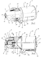
- the device according to the invention for providing packaging material is generally provided with the reference number 1.
- the device is referred to as packaging device 1.
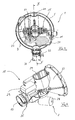
- the packaging apparatus 1 comprises as main components a packaging material receptacle 3 and a motor-driven forming section 5 fastened thereto, which is covered by two housing outer shells 7, 9.
- a control and / or control panel 11 with corresponding control actuators and buttons is provided in the region of the outside of the forming section 5.
- An exit opening 13 is limited inter alia by recesses on the front side of the housing outer shells 7, 9.
- the packaging material receptacle 3 consists of a metal cylinder 14 which is positively connected to a housing support 15 of the forming section 5 arranged inside the housing outer shells 7, 9 and which is closed on its side facing away from the exit opening 13 by a closing cover 17.
- a metal cylinder 14 extends in the axial direction A, which essentially corresponds to the conveying direction F of the packaging material, at least one viewing slot 19, by which an operator is to be displayed, by how much the packaging material lying within the packaging material receptacle 3, such as a paper web unwound from the inside of a paper roll, has already been used up.
- a mechanism 37 for opening the closure lid 17 is accommodated in a compartment 39 separate from the metal cylinder 14.
- the opening mechanism 37 allows pivoting of the end cover 17, wherein the pivot axis is parallel to the axial direction A of the packaging device 1 and the conveying direction F.
- the mechanism 37 has a fuse, which prevents operation of the motorized forming device 25 when the end cap 17 is not in the in the Figures 1 and 2 shown closure position on the metal cylinder 14 is located.
- a closure plug 21 can be actuated externally for removal on the forming section 5, which is inserted in a through-slot 23 formed on the housing carrier 15, by means of which manual access to a motor-driven forming device 25 is easily possible, comprising the packaging material for forming a specific filling material should deform and has a form gear pair for it.
- the form gear pair is operated by an electric motor 27 of the forming device 25, which is held on a passage shaft 23 opposite side of the housing support 15.
- a control electronics 29 is attached to the housing support 25.
- the packaging device 1 comprises at its underside a support flange 31, which is fastened to the packaging material receptacle 3 and over which the packaging device 1 can be attached to a vertical support column, not shown.
- an adjustment mechanism 32 which may be formed as a bolt-hole group arrangement, the packaging device 1 can be brought into various pivotal positions relative to the stationary vertical support column and horizontal direction, to facilitate the operator to direct the packaging material to a desired location ,
- the packaging material receptacle 3 is first equipped with a material web wound up into a roll (not shown).
- the roll of web material is unwound or withdrawn from the inside, as already described in the above-cited, generic packaging device according to DE 10 2005 053 319 A1 is specified.
- the inner end of the web roll is brought over the packaging material receptacle 3 to a feed hopper 33 of the housing support 25.
- a conveying of the packaging material towards the forming device is defined by the conical inner wall of the feed hopper 33 and fed to the form gear pair of the forming device 25.
- the motor-driven molding gears grasp the packaging material and deform it such that the desired filling material is formed.
- the filling material reaches a dispensing nozzle 35 of the housing support 15, which defines the outlet opening 13 of the housing support 25.
- the speed at which the shaped filling material leaves the exit opening can be adjusted by the operator via the control panel 11 connected to the control electronics 29.
- the protective cover 51 is frictionally inserted via a bayonet lock or inserted in a groove of the inner wall of the outlet opening 13 snapping or bolted to the inner wall.
- a tooth group 53 is provided in the outlet opening 13 in a circumferential ring portion so as to facilitate the tearing off of the deformed packaging material.
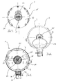
- the protective cover 51 has as a main component a circular, closed annular base 55, from the inner circumference of which a blocking or yielding structure 58 extends radially inwards.
- the base has a T-shape in cross-section, with the stem of the T-shape extending toward the inner wall of the housing support 15 to securely insert the base 55 in a complementary shape annular groove (not shown) in the exit port 13.
- a bayonet closure may be provided for a secure fit of the protective cover 51 in the outlet opening.
- the locking or yielding structure 58 is formed by eight arms 59 extending radially to the center M.
- the arms 59 always have a same outer shape, are formed wing or plate-like and have according to plan view Fig. 8 the shape of an isosceles triangle.
- the base side of the arms 59 is disposed on the inner periphery 57 of the ring base 55.
- the isosceles sides of the arms 59 extend toward the center M.
- the arms do not reach the center M, but form a free rounded end 63.
- the free ends 63 of the arms 59 are as shown in FIG Fig. 8 is shown on a (imaginary) circular boundary line B, which defines the circumference of the circular free passage 65. At least in the blocking state of the blocking or yielding structure 58, the boundary line is circular.
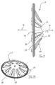
- the base side of the arms 59 lies in the same radial plane as the ring base 55, as in FIG. 9 is apparent.
- Each arm 59 is curved on both sides and leaves the radial plane of the ring base 55, away from the forming device 25, as in FIG. 2 is apparent.
- the forming device 25 facing side 71 of the arm 59 forms a convex curved surface, while the side facing away from the forming device 25 side forms a concave, flat surface 73.
- a radially extending stiffening rib 75 is provided on the concavely curved surface 73 of each arm 59.
- the arms 59 in their locked state extend from the ring base 55 over approximately two thirds of the radial center distance of the ring base 55 to the center M.
- the protective cover 51 has a hinge arrangement 71, which in the preferred embodiment according to the figures is formed by a joint 81 assigned to each arm, which consists of a single elastic material without rigid movable pivot axis.
- the hinge pivotally connects the arm 59 to the ring base 55.
- the joint 81 is so stiffened that a pivoting movement of the respective arm 59 about the ring base 55 toward the device 1, in particular the forming device 25 is blocked (in a locking direction P), while a pivoting movement away from the packaging device 1, in particular of the Forming device 25 away (in the conveying direction F) is allowed.
- the joints 81 each define a rectilinear or slightly curved pivot axis S which lie radially inwardly to the inner periphery 57 of the annular base 55.
- the joint 81 is designed as a hinge joint, which is realized by a material tapering 83 of the joint-forming elastomer body. Along the material taper 83, the pivot axis S.
- substantially axially projecting stop pins 85, 87 are provided which form a V-shaped clearance 89 between them when there is no force load on the arms 59.
- the stop pins 85, 87 serve to pivot the arms 59 in the reverse direction P (FIG. FIG. 9 ) to prevent. If the respective arm 59 is moved in the reverse direction P, the V-shaped free space 89 shrinks a little until the opposite abutment surfaces of the stop pins 85, 87 abut each other, whereby a further pivotal movement in the reverse direction P is blocked. The clearance 89 still allows a slight pivoting movement in the reverse direction P, in which the passage 65 is even reduced a little. Due to this slight reduction of the passage cross section, the operator is additionally informed that such a load in the interior of the packaging device 1 is an impermissible operation.
- each arm 59 may be provided with an axial nose 91 which extends substantially in the axial direction A towards the device 1 and may additionally cooperate with a housing part of the packaging device 1 for a movement stop in the reverse direction P.
- the housing part may be formed as a round flange, which extends radially inwardly and is positioned upstream of the protective cover.
- each arm 59 in cross-section has the greatest thickness approximately at the radial center.
- a special rigid arm structure is provided, which is to prevent elastic deformation of the arm 59 per se, so that access to the interior of the packaging device 1 is prevented as much as possible.
- the protective cover 51 can be made by a two-component injection molding process by making the rigid components such as the ring base 55 and the arm 59 from a rigid plastic, while the hinge assembly 71 is formed of a softer elastomeric material such as rubber ,
Landscapes
- Buffer Packaging (AREA)
- Closures For Containers (AREA)
Applications Claiming Priority (1)
| Application Number | Priority Date | Filing Date | Title |
|---|---|---|---|
| DE200810039616 DE102008039616A1 (de) | 2008-08-25 | 2008-08-25 | Schutzdeckel zum Positionieren an einer Ausgangsöffnung einer Vorrichtung zum Bereitstellen von Verpackungsmaterial |
Publications (2)
| Publication Number | Publication Date |
|---|---|
| EP2161121A2 true EP2161121A2 (fr) | 2010-03-10 |
| EP2161121A3 EP2161121A3 (fr) | 2011-02-02 |
Family
ID=41228337
Family Applications (1)
| Application Number | Title | Priority Date | Filing Date |
|---|---|---|---|
| EP09007214A Withdrawn EP2161121A3 (fr) | 2008-08-25 | 2009-05-29 | Couvercle de protection destiné au positionnement sur une ouverture de sortie d'un dispositif de préparation de matériaux d'emballage |
Country Status (2)
| Country | Link |
|---|---|
| EP (1) | EP2161121A3 (fr) |
| DE (1) | DE102008039616A1 (fr) |
Citations (1)
| Publication number | Priority date | Publication date | Assignee | Title |
|---|---|---|---|---|
| DE102005053319A1 (de) | 2005-11-07 | 2007-05-10 | Sprick Gmbh Bielefelder Papier- Und Wellpappenwerke & Co. | Vorrichtung und Verfahren zur Herstellung von Füllmaterial |
Family Cites Families (3)
| Publication number | Priority date | Publication date | Assignee | Title |
|---|---|---|---|---|
| DE4440877A1 (de) * | 1994-01-20 | 1995-07-27 | Thomas Quensel | Zustellbehälter für Kleingutsendungen |
| EP1827810B1 (fr) * | 2004-10-25 | 2009-09-30 | Ranpak Corp. | Systeme de production de matiere de rembourrage sans moteur |
| WO2006091789A2 (fr) * | 2005-02-22 | 2006-08-31 | Ranpak Corp. | Machine de conversion de fardage et protecteur de couloir d'ejection de sortie |
-
2008
- 2008-08-25 DE DE200810039616 patent/DE102008039616A1/de not_active Withdrawn
-
2009
- 2009-05-29 EP EP09007214A patent/EP2161121A3/fr not_active Withdrawn
Patent Citations (1)
| Publication number | Priority date | Publication date | Assignee | Title |
|---|---|---|---|---|
| DE102005053319A1 (de) | 2005-11-07 | 2007-05-10 | Sprick Gmbh Bielefelder Papier- Und Wellpappenwerke & Co. | Vorrichtung und Verfahren zur Herstellung von Füllmaterial |
Also Published As
| Publication number | Publication date |
|---|---|
| EP2161121A3 (fr) | 2011-02-02 |
| DE102008039616A1 (de) | 2010-03-04 |
Similar Documents
| Publication | Publication Date | Title |
|---|---|---|
| DE2638856C3 (de) | Zerbrechliche Strömungsmittelkupplung | |
| DE69508462T2 (de) | Originalitätsverschluss | |
| EP1492967B1 (fr) | Robot comprenant un dispositif de guidage de lignes | |
| EP3812329B1 (fr) | Unité de tambour à tuyau flexible et dispositif de tambour à tuyau flexible comprenant une unité de tambour à tuyau flexible | |
| EP2964860B1 (fr) | Mécanisme de commande pour une porte de meuble | |
| EP0786417B1 (fr) | Tube en plastique présentant un corps de tube et procédé pour sa fabrication | |
| EP3027443B1 (fr) | Élément de guidage d'air | |
| EP2913162B1 (fr) | Système de retour de conduite | |
| DE69803525T2 (de) | Verfahren und Vorrichtung zum Formen eines Schlauches und Vorrichtung zur Herstellung von Verpackungsbehältern | |
| WO2009010075A1 (fr) | Système de fermeture à rebond amovible pour un récipient | |
| EP2005042B1 (fr) | Dispositif d'étanchéité gonflable pour outil de formage | |
| EP0855223A2 (fr) | Tête de buse rotative | |
| EP2414155B1 (fr) | Couvercle de protection destiné à être placé sur une ouverture de sortie d'un dispositif de préparation de matériau d'emballage et dispositif doté d'un tel couvercle de protection | |
| EP4353447A1 (fr) | Appareil et procédé de production d'objets tridimensionnels | |
| EP3408547B1 (fr) | Élément d'alignement pour positionner une pièce de montage | |
| EP4021646A1 (fr) | Applicateur pour appliquer un composé d'étanchéité sur un pli de bordure | |
| DE602006000591T2 (de) | Gasfederstütze | |
| EP2251091B1 (fr) | Buse de rotor | |
| DE102010039036A1 (de) | Schraubverschluss mit Flexband | |
| WO2019238711A1 (fr) | Centrifugeuse | |
| DE102008039612A1 (de) | Vorrichtung zum Bereitstellen von Verpackungsmaterial | |
| DE202008018288U1 (de) | Schutzdeckel zum Positionieren an einer Ausgangsöffnung einer Vorrichtung zum Bereitstellen von Verpackungsmaterial | |
| EP2161121A2 (fr) | Couvercle de protection destiné au positionnement sur une ouverture de sortie d'un dispositif de préparation de matériaux d'emballage | |
| DE102007032372B4 (de) | Steigrohr für eine Austragvorrichtung für Medien | |
| EP3053493B1 (fr) | Dispositif de préparation de boissons |
Legal Events
| Date | Code | Title | Description |
|---|---|---|---|
| PUAI | Public reference made under article 153(3) epc to a published international application that has entered the european phase |
Free format text: ORIGINAL CODE: 0009012 |
|
| AK | Designated contracting states |
Kind code of ref document: A2 Designated state(s): AT BE BG CH CY CZ DE DK EE ES FI FR GB GR HR HU IE IS IT LI LT LU LV MC MK MT NL NO PL PT RO SE SI SK TR |
|
| AX | Request for extension of the european patent |
Extension state: AL BA RS |
|
| PUAL | Search report despatched |
Free format text: ORIGINAL CODE: 0009013 |
|
| AK | Designated contracting states |
Kind code of ref document: A3 Designated state(s): AT BE BG CH CY CZ DE DK EE ES FI FR GB GR HR HU IE IS IT LI LT LU LV MC MK MT NL NO PL PT RO SE SI SK TR |
|
| AX | Request for extension of the european patent |
Extension state: AL BA RS |
|
| STAA | Information on the status of an ep patent application or granted ep patent |
Free format text: STATUS: THE APPLICATION IS DEEMED TO BE WITHDRAWN |
|
| 18D | Application deemed to be withdrawn |
Effective date: 20110803 |