EP2161402B2 - Vorgefertigte Tür- oder Fensterrahmen-Einheit mit isolierender Randeinfassung - Google Patents
Vorgefertigte Tür- oder Fensterrahmen-Einheit mit isolierender Randeinfassung Download PDFInfo
- Publication number
- EP2161402B2 EP2161402B2 EP08425591.8A EP08425591A EP2161402B2 EP 2161402 B2 EP2161402 B2 EP 2161402B2 EP 08425591 A EP08425591 A EP 08425591A EP 2161402 B2 EP2161402 B2 EP 2161402B2
- Authority
- EP
- European Patent Office
- Prior art keywords
- frame
- counter
- surround
- wall
- insulating
- Prior art date
- Legal status (The legal status is an assumption and is not a legal conclusion. Google has not performed a legal analysis and makes no representation as to the accuracy of the status listed.)
- Active
Links
Images





Classifications
-
- E—FIXED CONSTRUCTIONS
- E06—DOORS, WINDOWS, SHUTTERS, OR ROLLER BLINDS IN GENERAL; LADDERS
- E06B—FIXED OR MOVABLE CLOSURES FOR OPENINGS IN BUILDINGS, VEHICLES, FENCES OR LIKE ENCLOSURES IN GENERAL, e.g. DOORS, WINDOWS, BLINDS, GATES
- E06B1/00—Border constructions of openings in walls, floors, or ceilings; Frames to be rigidly mounted in such openings
- E06B1/02—Base frames, i.e. template frames for openings in walls or the like, provided with means for securing a further rigidly-mounted frame; Special adaptations of frames to be fixed therein
Definitions
- This invention regards a counter-frame structure for a window, a French window or a skylight to be inserted in an opening in a wall or roof, separating the interior and exterior of a building.
- the frames are made with special attention to the selection of materials, inserting suitable insulation materials into the sections comprising the frames, for example a polystyrene or a polyurethane foam, and/or envisaging appropriate gaskets between the mobile and fixed parts of the frames. In this way it is sought to increase the frame's thermal cut-off and thus increase its insulation coefficient.
- suitable insulation materials for example a polystyrene or a polyurethane foam
- FR-A-2 539 801 discloses a prefabricated element suitable to be fitted into an opening of a wall for forming a decorative covering for the opening and making it possible to receive the framework of the corresponding doors or windows.
- the prefabricated element may be filled with a thermal insulating material.
- EP-A-1 455 027 discloses a heat insulation kit applied externally to a cellar ventilation window to prevent the formation of a heat bridge between the cellar well and the light shaft.
- U1 discloses a framework assembly including a door frame, window sash and a damming system, resting against the frame work assembly, formed according to building material class A1 or A2.
- EP-A-1 172 495 discloses a thermal insulation of the surround frame of a building opening, comprising at least two first heat insulating elements for arranging above and below the building opening, and at least two second heat insulating elements for arranging next to the first elements and lateral to the building opening.
- the purpose of this invention is to propose a counter-frame structure that gives the entire frame system greater thermal efficiency while at the same time obviating the installation drawbacks mentioned above.
- the other functional elements of the frame structure can be assembled at the time of installation since the structure is adaptable to any type of frame and blind or - most favourably - can be supplied to the building contractor already mounted on the structure.
- the structure is conceived for mounting prior to application of the insulating skin, taking into account the thickness thereof in such a way that subsequently any discontinuity between frame and wall can be eliminated. Insulation of inclined external surfaces or reveals can be carried out at various angulations.
- the structure in accordance with the invention reduces, if it does not eliminate, the thermal bridges still found in state of the art frames, in particular between wall and counter-frame, between wall and reveals insulation and between wall and skin, all of this without burdensome building work. In other words, once installed the frame is already completely insulated.
- the structure is conceived in such a way that various types and sizes of insulation may be used, e.g. up to 400 mm thickness.
- a further advantage is that the customer can deal with one single supplier for counter-frame, frame insulation, blinds and internal/external sills.
- the counter-frame structure is applicable to frames in any material whatsoever, e.g. wood, aluminium, PVC or combinations thereof, and can be used in various types of buildings such as prefabs, traditional buildings in masonry and concrete and also in renovations.
- the counter-frame structure of the present invention comprises a counter-frame 10 for door and window frames and an insulating surround 12, in heat insulation material, which surrounds counter-frame 10 at least on the sides facing wall 5 in which it is to be placed and facing the exterior of the said wall.
- Counter-frame 10 and insulating surround 12 are connected in such a way as to form a single block 1; 2 to be inserted in an opening in wall 5.
- thermoplastic polymeric material in particular a polystyrene.
- the insulating surround 12 is of such thickness as to extend between internal side 5' and external side 5" of wall 5 in which the structure is inserted.
- a thickness of insulating surround 12 permits, in the upper part, incorporation of a recess or other containing and guiding devices for the blind elements 42,48 of the frame and, in the lower part, the creation of a support base for the internal 22 and external window sills 23.
- the counter-frame structure is suitable for insertion in a wall 5 consisting of a part in masonry 6 and an external protective facing known as "skin" 7.
- the insulating surround 12 extends frontally to the level of skin 7 in such a way as to create a continuous insulation between the heat insulation material of the surround 12 and that of skin 7.
- surround 12 comprises a frontal portion 7a with the same thickness and in the same material as skin 7, and a rear portion 6a, also in insulating material, corresponding to the thickness of the masonry part 6.
- the counter-frame structure can be adapted to the size of the space and therefore inserted in the wall 5 with extreme precision, connecting it up with insulating materials to the elements comprising the wall itself.
- the internal and external surfaces of insulating surround 12, meaning those facing the interior 5' and exterior 5" of the building, are covered with a layer of rendering 14 which extends to conceal counter-frame 10.
- the rendering operation usually carried out with the counter-frame 10 installed, takes place at building phase, thus avoiding soiling or damaging the counter-frame 10 at the door/window installation phase.
- a pre-rendering operation is carried out in such a way that, having mounted the counter-frame 10, the builders then carry out a final rendering that connects the external surface of the counter-frame structure with the wall 5 of the building.
- the coat of rendering 14 or pre-rendering is laid on scrim or template 16 which covers the internal and external surfaces of insulating surround 12.
- insulating surround 12 is profiled in such a way as to define at least one housing 18 for a blind element 42,48 (as will be better specified below in the description of examples of implementation).
- the insulating surround 12 integrates, or is equipped to integrate, at least certain functional elements of the door/window-frame 32 such as guides for sliding parts 44,49 and sealing elements against water or dust.
- the guides 44,49 for rolling or sliding elements are created in insulating surround 12 at a distance from the elements of counter-frame-10 in such a way as to interpose layer 12" of heat insulation material. This results in avoiding or reducing the effect of any thermal bridge that would be created by contact between the said guides and counter-frame 10.
- the insulating surround 12 includes a base element 20 which can be covered by at least one plate in such a way as to create internal sill 22 and/or external sill 23 of the window-frame 32.
- the insulating surround 12 extends in such a way as to at least partially overlap frame 30 which is fixed, or will be fixed upon installation, to counter-frame 10. At least partial overlapping is understood as being at least from the part facing the exterior 5". In fact in this way the external side of frame 30 is covered by insulating surround 12 and therefore benefits from greater thermal protection. Having thus limited cooling of the exposed surface of frame 30, heat dispersion from interior 5' to exterior 5" by way of the frame 30 is therefore avoided right from the start.
- the insulating surround 12 actually extends also to overlap the opening window-frame 32 in such a way that only the glazed part is visible from outside. In this case, over and above the aesthetic result, external surface cooling of both frame 30 and opening window-frame 32 is avoided, thus reducing overall heat dispersion.
- the use of a surround 12 in heat-insulation material that extends to the external surface 5" of the wall 5, with the possibility of easily forming the surround elements according to taste means that the frame structure can be connected to the said external surface 5' with special lines, for example with inclined surfaces 36 that open towards the exterior. This among other things means maximising the entry of light through the door/window frame, especially when the surround 12 overlaps the frame. It should be noted that to date the same result has been sought by breaking the wall 5 or the external protective skin 7, with considerable negative consequences in terms of time and costs.
- insulating surround 12 is formed by a plurality of elements 12', for example in the form of square bars or blocks, closely coupled in such a way as to leave no interstices through which heat could be propagated.
- These elements 12' of surround 12 are coupled by means of flat and extended contact surfaces or, even more favourably, are linked with a geometrical or jointed coupling.
- the elements 12' of surround 12 are fixed to counter-frame 10 of the door/ window-frame.
- said elements 12' of surround 12 are fixed to the counter-frame 10 by gluing and/or by screwing and/or by means of clamps or profiled sheet metal.
- the upper and lower horizontal sides 10' and vertical sides or uprights 10" that define the sides of counter-frame 10, and the adjacent elements of surround 12, are profiled to be coupled geometrically or by a joint.
- the said sides 10', 10" of counter-frame 10 have a longitudinal channel 11 in which a corresponding longitudinal projection 13 of the surround elements is inserted.
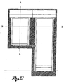
- Figures 1 and 2 illustrate two counter-frame structures of a window and a French window respectively, in accordance with the invention, seen from the interior.
- the said figures show the counter-frame 10 (including upper and lower horizontal sides 10' and vertical sides or uprights 10") with the insulating surround 12, formed by elements 12', 20.
- a box 40 for a roller blind 42 ( figures 3 and 4 ), also inserted in surround 12 and, in figure 1 , an internal sill 22.
- no base element 20 is provided as support for sills 22, 23, but the surround 12 terminates in any case with a lower horizontal bar 20' suitable for setting into the floor to prevent the passage of heat from the lower part of the frame.
- lateral elements 12' of insulating surround 12 extend in the lower part to the level of the lower extremity of bar 20'.
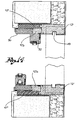
- Figures 3 and 4 illustrate a vertical section of counter-frame structure 1 for a window, before and after fixing of the actual door/window-frame 30, 32 to counter-frame 10.
- the internal and external sills 22 and 23 can be seen resting on base element 20.
- the upper horizontal element 12' of surround 12 has, frontally, towards the exterior of the door/window-frame, a box structure suitable for delimiting housing 18 for a box 40 containing a roller blind element 42.
- insulating surround 12 comprises, as well as the upper element mentioned above that rests on the jamb of the counter-frame 10, a further profiled section indicated as 12a which covers the frontal side of counter-frame 10 and also extends to overlap frame 30.
- profile 12a of surround 12 and the upper horizontal side 10' of the counter-frame 10 are coupled geometrically with a male (longitudinal projection 13)-female (longitudinal channel 11) type joint.
- An analogous arrangement of the elements of the counter-frame 10 and the insulating surround 12 are found in the lower part of the counter-frame structure.
- Figures 3 and 4 moreover show guide 44 for movement of roller blind element 42.
- Figure 5 moreover shows a horizontal element 10a for fixing surround 12 to counter-frame 10.
- This horizontal element 10a for example a wooden bar, is sunk into upper transversal element 12' of surround 12 to connect the latter, e.g. by means of screws, to the lower horizontal side 10' of counter-frame 10.
- Figures 8 and 9 illustrate a simpler counter-frame structure for a window, e.g. for a window with shutters, therefore without an integrated blind element.
- the upper part of surround 12 is limited to profile 12a which is joint-coupled frontally with upper horizontal side 10' of counter-frame 10.
- Note in figure 9 the presence of a pair of vertical bars 46 set in insulating profiles 12', e.g. in the same material as counter-frame 10, which serve as supports for the shutter hinges.
- horizontal element 12a of surround 12 partially covers window frame 30 while vertical elements 12' of surround 12, which are joint-coupled with uprights 10" of the counter-frame 10, completely cover frame 30.
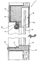
- Figure 10 is a vertical section view of a counter-frame structure for a window with an adjustable slats blind device 48. Apart from the different blind element the structure of the counter-frame block-insulating surround is substantially the same as that of figures 3 and 4 .
- Figure 11 illustrates a counter-frame structure analogous to the previous one but for a French window.
- the lower part of the structure features a lower bar 20' of the surround 12, set in the floor and in any case fixed to counter-frame 10.
- guide 49 for the adjustable slats is obtained in the centre of side profiles 12' of surround 12, well spaced from counter-frame 10. Also note in this case the presence of insulating perimeter elements 6a and 7a of the wall connection which is fixed, e.g. by gluing, to counter-frame 10 and vertical uprights 12' of surround 12. Said vertical uprights 12' of surround 12 completely cover window frame 30 and are joint-coupled to vertical uprights 10" of counter-frame 10.
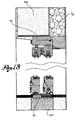
- Figure 13 is a vertical section view of counter-frame structure for a sliding French window without blind.
- insulating surround 12 includes the wall connection elements and a frontal crosspiece that partially covers the sliding frame, joint-coupled to upper horizontal slide 10' of counter-frame 10.
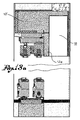
- Figure 13a again referring to a counter-frame structure for sliding doors, differs from the previous one inasmuch as we have housing 18 for a blind element. Note how housing 18 is obtained from the bringing together of frontal profile 12a, which in this case extends below to a greater extent, completely protecting the window frame, with an upper horizontal profile 12' and thus creating the necessary thickness to obtain housing 18.
- the horizontal section of figure 14 shows two side insulation profiles 12' which also integrate guide 49 for the blind element and further vertical insulation profiles 12b that fill the empty space between frame and sliding door.
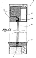
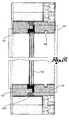
- FIGS 15 and 16 concern a further example of application of the invention. More precisely a counter-frame structure for a window with fixed glazing 50, which can be shaded with adjustable slats element 48, of which it can be noted the housing 18, provided in the upper part of insulating surround 12, and sliding guides 49 integrated in vertical insulation profiles. Most favourably, the glazing 50 is directly fixed to counter-frame 10, completely enclosed by insulating surround 12. Also at the level of the vertical uprights of the structure, surround 12 extends both forward and rearward with regard to counter-frame 10.
Landscapes
- Engineering & Computer Science (AREA)
- Civil Engineering (AREA)
- Structural Engineering (AREA)
- Wing Frames And Configurations (AREA)
- Door And Window Frames Mounted To Openings (AREA)
- Residential Or Office Buildings (AREA)
- Securing Of Glass Panes Or The Like (AREA)
Claims (22)
- Verwendung einer Rahmen-Gegenstruktur für Tür-/Fensterrahmen zum Einsetzen in eine Öffnung in einer Außenwand (5) eines Gebäudes, wobei die Rahmen-Gegenstruktur Folgendes aufweist:- einen Gegenrahmen (10) für einen Tür-/Fensterrahmen;- eine isolierende Randeinfassung (12) in einem Wärmeisolationsmaterial, welches den Gegenrahmen (10) mindestens auf den der Wand (5) und dem Gebäude-Äußeren zugewandten Seiten umschließt,
dadurch gekennzeichnet, dass der Gegenrahmen (10) und die isolierende Randeinfassung (12) so miteinander verbunden sind, dass sie einen einzigen in die Öffnung in der Wand (5) einzusetzenden Block (1; 2) bilden, mindestens ein Gehäuse (18) für einen Kasten (40) einer Jalousie (42, 48), das frontal in Richtung des Gebäude-Äußeren in einem oberen Teil (12') der isolierenden Randeinfassung (12) ausgearbeitet ist,
wobei die Wand (5) zum Teil aus Mauerwerk (6) und einer äußeren Schutzhaut (7) besteht, und in der die isolierende Randeinfassung (12) eine solche Dicke aufweist, so dass sie sich zwischen der inneren Seite (5') und der äußeren Seite (5") der Wand (5) erstreckt, in die die Struktur eingesetzt ist, derart, dass sich die isolierende Randeinfassung (12) frontal bis hin zur Haut (7) so erstreckt, dass eine kontinuierliche Isolierung zwischen dem Wärmeisolationsmaterial und der isolierenden Randeinfassung (12) und derjenigen der Haut (7) erzeugt wird. - Verwendung nach Anspruch 1, wobei die innere und die äußere Oberfläche der isolierenden Randeinfassung mit einer Schicht von Putz (14) oder Vorputz bedeckt sind, der sich zum Verkleiden des Gegenrahmens erstreckt.
- Verwendung nach Anspruch 2, wobei die innere (5') und die äußere (5") Oberfläche der isolierenden Randeinfassung (12) durch einen Gitterstoff oder ein Templat (16) bedeckt sind, auf das die Putzschicht (14) oder der Vorputz aufgebracht ist oder aufgebracht werden kann.
- Verwendung nach einem der vorangehenden Ansprüche, wobei die isolierende Randeinfassung (12) ein Gehäuse (18) für einen Rolladen (42) oder verstellbare Lamellenjalousien (48) umfasst.
- Verwendung nach einem der vorangehenden Ansprüche, wobei die isolierende Randeinfassung (12) aufnimmt oder geeignet ist zum Aufnehmen von mindestens einigen Funktionselementen des Rahmens, wie Führungen (44; 49) für gleitende Teile und für wasserdichte/staubdichte Dichtteile.
- Verwendung nach Anspruch 5, wobei die Führungen für die Gleitelemente in der isolierenden Randeinfassung (12) in einem Abstand von den Elementen (10', 10") des Gegenrahmens (10) so eingearbeitet sind, dass ein Zwischenraum für eine Schicht (12') von wärmeisolierendem Material gelassen wird.
- Verwendung nach einem der vorangehenden Ansprüche, wobei die isolierende Randeinfassung (12) ein Basiselement (20) aufweist, auf das mindestens eine Platte so aufgesetzt ist, dass sie die innere Fensterbank (23) und/oder die äußere Fensterbank (42) des Rahmens erzeugt.
- Verwendung nach einem der vorangehenden Ansprüche, wobei die isolierende Randeinfassung (12) Teile von aufrechten (10") und Teile von oberen/unteren horizontalen Seiten (10') aufweist, die jeweils von einem Profil (34) aus Metall oder Kunststoffmaterial bedeckt sind, das dazu ausgelegt ist, sichtbar zu bleiben.
- Verwendung nach einem der vorangehenden Ansprüche, wobei die isolierende Randeinfassung (12) zum mindestens teilweisen Überlappen des nach außen weisenden Rahmen (30)-Teils ausgelegt ist.
- Verwendung nach Anspruch 9, wobei die isolierende Randeinfassung (12) auch zum Überlappen des Türrahmens (32) auf eine solche Weise geeignet ist, dass von außen nur die Verglasung (50) des Rahmens sichtbar ist.
- Verwendung nach einem der vorangehenden Ansprüche, wobei die isolierende Randeinfassung (12) mit der äußeren Seite (5 ") der Wand (5) über schräge Flächen (36) so verbunden ist, dass der Eintritt von Licht durch den Rahmen maximiert wird.
- Verwendung nach einem der vorangehenden Ansprüche, wobei die isolierende Randeinfassung (12) eine Vielzahl von eng gekoppelten Elementen (12', 12a, 12b) umfasst, wovon mindestens einige der Elemente an dem Gegenrahmen (10) befestigt sind.
- Verwendung nach Anspruch 12, wobei die Elemente (12', 12a, 12b) der isolierenden Randeinfassung miteinander mit einer geometrischen oder Gelenkkopplung verbunden sind.
- Verwendung nach Anspruch 13, wobei die Elemente (12', 12a, 12b) der isolierenden Randeinfassung (12) an dem Gegenrahmen (10) mit einer Gelenkkopplung und/oder durch Kleben und/oder durch Schrauben und/oder durch Klemmen oder profiliertes Metallblech befestigt sind.
- Verwendung nach einem der vorangehenden Ansprüche, wobei der Rahmen ein Bodenfenster ist, und wobei die isolierende Randeinfassung (12) eine untere Schiene (20') aufweist, die zum Einsetzen in ein Gehäuse im Boden geeignet ist.
- Verwendung nach einem der vorangehenden Ansprüche, wobei die isolierende Randeinfassung (12) einen vorderen Teil (7a) der gleichen Dicke und aus dem gleichen Material wie die Schutzhaut (7) der Wand (5) und einen hinteren Teil (6a) entsprechend der Dicke des Teils der Wand (5) im Mauerwerk aufweist.
- Verwendung nach einem der vorangehenden Ansprüche, aufweisend einen Tür-/Fensterrahmen (30), der an dem Gegenrahmen (10) befestigt ist.
- Verwendung nach Anspruch 17, aufweisend einen kompletten Rahmen (30, 32), der an dem Gegenrahmen (10) befestigt ist.
- Verfahren zur Herstellung und zum Einsetzen eines Tür-/Fensterrahmens (30) in eine Öffnung einer Außenwand (5) eines Gebäudes, wobei die Wand (5) zum Teil aus Mauerwerk (6) und einer äußeren Schutzhaut (7) besteht, umfassend die folgenden Schritte:- Ausbilden eines Gegenrahmens (10)L- Ausbilden einer isolierenden Randeinfassung (12) in einem Wärmeisolationsmaterial;- Ausbilden mindestens eines Gehäuses (18) für einen Kasten (40) einer Jalousie (42, 48) frontal, in Richtung des Äußeren des Gebäudes in einem oberen Teil (12') der isolierenden Randeinfassung (12);- Einfassen des Gegenrahmens (10) mit der Randeinfassung (12) so, dass sie mindestens die Seiten des Gegenrahmens (12), die der Wand zugewandt sind, in die er einzusetzen ist, und dem Äußeren (5') des Gebäudes zugewandt, bedeckt;- Befestigen der Randeinfassung (12) an dem Gegenrahmen (10) so, dass ein einziger Block (12) gebildet wird,- Einsetzen des Blocks (12) in die Öffnung der Wand (5) oder des Dachs,- wobei die isolierende Randeinfassung von einer solchen Dicke ist, dass sie sich zwischen der inneren Seite (5') und der äußeren Seite (5 ") der Wand (5) erstreckt, in die die Struktur eingebaut wird, derart, dass die isolierende Randeinfassung sich frontal bis zu der Haut (7) so erstreckt, dass eine kontinuierliche Isolierung zwischen dem wärmeisolierenden Material und der isolierenden Randeinfassung (12) und derjenigen der Haut (7) erzeugt wird.
- Verfahren nach Anspruch 19, wobei vor dem Einbau in die Öffnung der Block (1, 2) mit Zement verputzt oder vorverputzt wird.
- Verfahren nach Anspruch 20, wobei, nachdem der Block (12) verputzt ist, und bevor vor dem Einsetzen in die Wand (5) oder das Dach, der Rahmen (10) an dem Block (12) befestigt wird.
- Verfahren nach einem der Ansprüche 19 bis 21, wobei vor dem Einbau in die Öffnung ein Jalousienelement (42, 48) und sein Zubehör montiert werden.
Priority Applications (9)
| Application Number | Priority Date | Filing Date | Title |
|---|---|---|---|
| PL08425591T PL2161402T3 (pl) | 2008-09-05 | 2008-09-05 | Prefabrykowana jednostka ramowa drzwi lub okna z obramowaniem izolującym |
| EP10196965.7A EP2333219B2 (de) | 2008-09-05 | 2008-09-05 | Vorgefertigte Tür- oder Fensterrahmen-Einheit mit isolierender Randeinfassung |
| SI200830219T SI2161402T1 (sl) | 2008-09-05 | 2008-09-05 | Predizdelana enota okvirja vrat ali oken z izolirnim okvirjem |
| DE602008004523T DE602008004523D1 (de) | 2008-09-05 | 2008-09-05 | Vorgefertigte Tür- oder Fensterrahmen-Einheit mit isolierender Randeinfassung |
| DK08425591.8T DK2161402T3 (da) | 2008-09-05 | 2008-09-05 | Præfabrikeret dør- eller vinduesrammenhed med en isolerende indfatning |
| AT08425591T ATE495336T2 (de) | 2008-09-05 | 2008-09-05 | Vorgefertigte tür- oder fensterrahmen-einheit mit isolierender randeinfassung |
| EP08425591.8A EP2161402B2 (de) | 2008-09-05 | 2008-09-05 | Vorgefertigte Tür- oder Fensterrahmen-Einheit mit isolierender Randeinfassung |
| ES08425591T ES2359661T3 (es) | 2008-09-05 | 2008-09-05 | Unidad prefabricada de marco de puerta o ventana con una periferia de aislamiento. |
| HR20110118T HRP20110118T1 (hr) | 2008-09-05 | 2011-02-17 | Montažni okvirni element za vrata ili prozor s izolacijskim okruženjem |
Applications Claiming Priority (1)
| Application Number | Priority Date | Filing Date | Title |
|---|---|---|---|
| EP08425591.8A EP2161402B2 (de) | 2008-09-05 | 2008-09-05 | Vorgefertigte Tür- oder Fensterrahmen-Einheit mit isolierender Randeinfassung |
Related Child Applications (2)
| Application Number | Title | Priority Date | Filing Date |
|---|---|---|---|
| EP10196965.7A Division EP2333219B2 (de) | 2008-09-05 | 2008-09-05 | Vorgefertigte Tür- oder Fensterrahmen-Einheit mit isolierender Randeinfassung |
| EP10196965.7A Division-Into EP2333219B2 (de) | 2008-09-05 | 2008-09-05 | Vorgefertigte Tür- oder Fensterrahmen-Einheit mit isolierender Randeinfassung |
Publications (3)
| Publication Number | Publication Date |
|---|---|
| EP2161402A1 EP2161402A1 (de) | 2010-03-10 |
| EP2161402B1 EP2161402B1 (de) | 2011-01-12 |
| EP2161402B2 true EP2161402B2 (de) | 2016-10-26 |
Family
ID=40329428
Family Applications (2)
| Application Number | Title | Priority Date | Filing Date |
|---|---|---|---|
| EP10196965.7A Active EP2333219B2 (de) | 2008-09-05 | 2008-09-05 | Vorgefertigte Tür- oder Fensterrahmen-Einheit mit isolierender Randeinfassung |
| EP08425591.8A Active EP2161402B2 (de) | 2008-09-05 | 2008-09-05 | Vorgefertigte Tür- oder Fensterrahmen-Einheit mit isolierender Randeinfassung |
Family Applications Before (1)
| Application Number | Title | Priority Date | Filing Date |
|---|---|---|---|
| EP10196965.7A Active EP2333219B2 (de) | 2008-09-05 | 2008-09-05 | Vorgefertigte Tür- oder Fensterrahmen-Einheit mit isolierender Randeinfassung |
Country Status (8)
| Country | Link |
|---|---|
| EP (2) | EP2333219B2 (de) |
| AT (1) | ATE495336T2 (de) |
| DE (1) | DE602008004523D1 (de) |
| DK (1) | DK2161402T3 (de) |
| ES (1) | ES2359661T3 (de) |
| HR (1) | HRP20110118T1 (de) |
| PL (1) | PL2161402T3 (de) |
| SI (1) | SI2161402T1 (de) |
Families Citing this family (11)
| Publication number | Priority date | Publication date | Assignee | Title |
|---|---|---|---|---|
| ITRM20100542A1 (it) * | 2010-10-13 | 2012-04-14 | Paolo Gusmeroli | "falso telaio prefabbricato con struttura a sandwich per vani porta e finestra" |
| EP2479369B1 (de) | 2011-01-20 | 2016-07-13 | Südtirol Fenster S.r.l. | Vorgefertigte Fensterrahmeneinheit mit isolierender Randeinfassung und integriertem Sims |
| CN103867072B (zh) * | 2012-12-12 | 2016-07-06 | 贵阳铝镁设计研究院有限公司 | 一种保温节能的外墙窗的制作方法及结构 |
| CN103590735A (zh) * | 2013-12-02 | 2014-02-19 | 哈尔滨森鹰窗业股份有限公司 | 带有电动百叶的四玻铝包木窗 |
| CN104153677B (zh) * | 2014-07-18 | 2016-03-02 | 天津金木共生科技有限公司 | 一种铝木复合门窗 |
| PL414259A1 (pl) * | 2015-10-04 | 2017-04-10 | Marbet Spółka Z Ograniczoną Odpowiedzialnością | Sposób montażu stolarki otworowej i zestaw elementów montażowych stolarki otworowej |
| FR3083258B1 (fr) | 2018-06-29 | 2020-12-25 | Afl Foessel | Ensemble pour l'installation et/ou la renovation d'une fenetre |
| FR3083257B1 (fr) | 2018-06-29 | 2020-12-25 | Afl Foessel | Ensemble comprenant un pre-cadre et un dormant de fenetre monte dans le pre-cadre |
| CN111005646A (zh) * | 2019-12-11 | 2020-04-14 | 华东建筑设计研究院有限公司 | 一种超低能耗建筑外窗结构及其施工方法 |
| EP3854975B1 (de) | 2020-01-23 | 2022-12-21 | Daw Se | Vorgefertigte umfassungszarge für eine gebäudeöffnung, wärmedämmverbundsystem, gebäudefassade und gebäude, enthaltend die umfassungszarge, und verwendung der umfassungszarge |
| WO2024130370A1 (pt) * | 2022-12-21 | 2024-06-27 | Soares Clayvert De Faria | Porta antiesmagamento, borda flexível, componente rígido, folha de porta e sistema de porta antiesmagamento |
Citations (8)
| Publication number | Priority date | Publication date | Assignee | Title |
|---|---|---|---|---|
| DE3119692A1 (de) † | 1981-05-18 | 1982-12-02 | Heinz Ing.(grad.) 8644 Pressig Carl | Vorfertigbares bauelement |
| EP0132779A2 (de) † | 1983-07-23 | 1985-02-13 | Hans Schlitzberger | Fensterzarge |
| DE29519675U1 (de) † | 1995-12-12 | 1996-02-01 | Endter, Walter Josef, 98529 Suhl | Bauelement |
| AT401280B (de) † | 1992-11-12 | 1996-07-25 | Kraler Franz | Verlorene schalung mit einem ersten schalungsabschnitt |
| DE19951901A1 (de) † | 1999-10-28 | 2001-05-03 | Bernd Beck | Bauelement |
| DE10040497C1 (de) † | 2000-08-18 | 2001-10-11 | Gutmann Hermann Werke Gmbh | Zarge für ein Fenster oder eine Tür in wärmegedämmter Ausführung |
| FR2822495A1 (fr) † | 2001-03-21 | 2002-09-27 | Christian Triomphe | Bloc baie integre manuportable conforme a la nouvelle reglementation thermique 2001 pret a la pose dans les elements de gros oeuvre monte a la colle |
| AT412190B (de) † | 2002-10-25 | 2004-11-25 | Fries Planung & Marketing | Stapelbarer geschirrkorb für geschirrspülmaschinen |
Family Cites Families (9)
| Publication number | Priority date | Publication date | Assignee | Title |
|---|---|---|---|---|
| DE2557878C3 (de) * | 1975-12-22 | 1980-02-21 | Heinrich 5400 Koblenz Schultes | Schallschutzfenster |
| FR2539801B1 (fr) | 1983-01-20 | 1985-08-23 | Rogez Patrice | Procede de finition en particulier au niveau des ouvertures formees dans le gros oeuvre de batiments et elements prefabriques pour la mise en oeuvre de ce procede |
| DE29808250U1 (de) * | 1998-05-07 | 1998-08-27 | Koch Marmorit Gmbh, 79283 Bollschweil | Vorgefertigtes Bauelement |
| DE29900597U1 (de) | 1999-01-15 | 2000-06-29 | D & M Rolladentechnik GmbH, 56204 Hillscheid | Rolladenvorrichtung |
| DE19905622A1 (de) | 1999-02-11 | 2000-08-17 | Gerd Heinrichs | Elemente zum Dämmen von Außenöffnungen, wie Fenster und Türen, die gleichzeitig auch rationelle Einbauhilfe für die Einbauteile dieser Öffnungen sind |
| EP1172495B1 (de) * | 2000-07-12 | 2005-09-28 | Knauf Marmorit GmbH | Wärmedämmung für die Leibung einer Gebäudeöffnung |
| AT412109B (de) | 2002-12-27 | 2004-09-27 | Kraler Franz | Verlorene schalung |
| DE20303405U1 (de) * | 2003-03-03 | 2003-07-17 | Josef Hain GmbH & Co. KG, 83561 Ramerberg | Wärmedämmelement |
| DE202006004425U1 (de) | 2006-03-17 | 2006-06-01 | Rehau Ag + Co. | Rahmenbaugruppe |
-
2008
- 2008-09-05 AT AT08425591T patent/ATE495336T2/de active
- 2008-09-05 DK DK08425591.8T patent/DK2161402T3/da active
- 2008-09-05 PL PL08425591T patent/PL2161402T3/pl unknown
- 2008-09-05 ES ES08425591T patent/ES2359661T3/es active Active
- 2008-09-05 EP EP10196965.7A patent/EP2333219B2/de active Active
- 2008-09-05 DE DE602008004523T patent/DE602008004523D1/de active Active
- 2008-09-05 EP EP08425591.8A patent/EP2161402B2/de active Active
- 2008-09-05 SI SI200830219T patent/SI2161402T1/sl unknown
-
2011
- 2011-02-17 HR HR20110118T patent/HRP20110118T1/hr unknown
Patent Citations (8)
| Publication number | Priority date | Publication date | Assignee | Title |
|---|---|---|---|---|
| DE3119692A1 (de) † | 1981-05-18 | 1982-12-02 | Heinz Ing.(grad.) 8644 Pressig Carl | Vorfertigbares bauelement |
| EP0132779A2 (de) † | 1983-07-23 | 1985-02-13 | Hans Schlitzberger | Fensterzarge |
| AT401280B (de) † | 1992-11-12 | 1996-07-25 | Kraler Franz | Verlorene schalung mit einem ersten schalungsabschnitt |
| DE29519675U1 (de) † | 1995-12-12 | 1996-02-01 | Endter, Walter Josef, 98529 Suhl | Bauelement |
| DE19951901A1 (de) † | 1999-10-28 | 2001-05-03 | Bernd Beck | Bauelement |
| DE10040497C1 (de) † | 2000-08-18 | 2001-10-11 | Gutmann Hermann Werke Gmbh | Zarge für ein Fenster oder eine Tür in wärmegedämmter Ausführung |
| FR2822495A1 (fr) † | 2001-03-21 | 2002-09-27 | Christian Triomphe | Bloc baie integre manuportable conforme a la nouvelle reglementation thermique 2001 pret a la pose dans les elements de gros oeuvre monte a la colle |
| AT412190B (de) † | 2002-10-25 | 2004-11-25 | Fries Planung & Marketing | Stapelbarer geschirrkorb für geschirrspülmaschinen |
Also Published As
| Publication number | Publication date |
|---|---|
| DK2161402T3 (da) | 2011-03-14 |
| EP2333219B1 (de) | 2018-12-19 |
| ES2359661T3 (es) | 2011-05-25 |
| EP2333219B2 (de) | 2024-12-11 |
| DE602008004523D1 (de) | 2011-02-24 |
| EP2161402B1 (de) | 2011-01-12 |
| EP2333219A1 (de) | 2011-06-15 |
| PL2161402T3 (pl) | 2011-06-30 |
| EP2161402A1 (de) | 2010-03-10 |
| SI2161402T1 (sl) | 2011-05-31 |
| ATE495336T2 (de) | 2011-01-15 |
| HRP20110118T1 (hr) | 2011-03-31 |
Similar Documents
| Publication | Publication Date | Title |
|---|---|---|
| EP2161402B2 (de) | Vorgefertigte Tür- oder Fensterrahmen-Einheit mit isolierender Randeinfassung | |
| EP2479369A1 (de) | Vorgefertigte Fensterrahmeneinheit mit isolierender Randeinfassung und integriertem Sims | |
| CN101351611A (zh) | 结构元件 | |
| GB2228033A (en) | Method of, and strip means for, installing a window or door frame in a building | |
| JP4928371B2 (ja) | 建具周囲の排水構造 | |
| AU2007302888A1 (en) | Improved sill flashing | |
| WO1989008767A1 (en) | Improvements in the installation of roller shutters | |
| AU686700B2 (en) | Door frame and components therefor | |
| JP2001317271A (ja) | 建物外壁の開口部周辺構造 | |
| GB2363418A (en) | Profile portion including a cavity closer and a cill carrier | |
| US20070245649A1 (en) | Exterior casing trim | |
| AU750987B2 (en) | Adjustable facade shell with a support structure for a building | |
| JP3232267B2 (ja) | 改装サッシ | |
| GB2311127A (en) | Ventilation adjacent to window or door assemblies | |
| CN110621843A (zh) | 用于窗户的遮盖装置 | |
| GB2191529A (en) | Window frame | |
| JP3233577B2 (ja) | サッシ窓 | |
| EP1529917A2 (de) | Fenster oder Türkonstruktion und sein Einbauverfahren in einem Gebäude | |
| NL1018029C2 (nl) | Kozijncombinatie. | |
| GB2351313A (en) | A bay window sub-frame including a cavity closer | |
| CH671995A5 (en) | Prefab. metal frame for window opening - has faces for connection to window frame and shutter guide, and has sloping sill and top member | |
| AU2006100147A4 (en) | Seal for through-wall opening | |
| JP2025159986A (ja) | 建具 | |
| AU2023216872A1 (en) | Closure framing system | |
| EP2048300B1 (de) | Vorgefertigte Wand mit Fenster oder Tür |
Legal Events
| Date | Code | Title | Description |
|---|---|---|---|
| PUAI | Public reference made under article 153(3) epc to a published international application that has entered the european phase |
Free format text: ORIGINAL CODE: 0009012 |
|
| AK | Designated contracting states |
Kind code of ref document: A1 Designated state(s): AT BE BG CH CY CZ DE DK EE ES FI FR GB GR HR HU IE IS IT LI LT LU LV MC MT NL NO PL PT RO SE SI SK TR |
|
| AX | Request for extension of the european patent |
Extension state: AL BA MK RS |
|
| 17P | Request for examination filed |
Effective date: 20100326 |
|
| 17Q | First examination report despatched |
Effective date: 20100416 |
|
| GRAP | Despatch of communication of intention to grant a patent |
Free format text: ORIGINAL CODE: EPIDOSNIGR1 |
|
| GRAS | Grant fee paid |
Free format text: ORIGINAL CODE: EPIDOSNIGR3 |
|
| AKX | Designation fees paid |
Designated state(s): AT BE BG CH CY CZ DE DK EE ES FI FR GB GR HR HU IE IS IT LI LT LU LV MC MT NL NO PL PT RO SE SI SK TR |
|
| AXX | Extension fees paid |
Extension state: MK Payment date: 20100326 Extension state: RS Payment date: 20100326 Extension state: BA Payment date: 20100326 Extension state: AL Payment date: 20100326 |
|
| GRAA | (expected) grant |
Free format text: ORIGINAL CODE: 0009210 |
|
| AK | Designated contracting states |
Kind code of ref document: B1 Designated state(s): AT BE BG CH CY CZ DE DK EE ES FI FR GB GR HR HU IE IS IT LI LT LU LV MC MT NL NO PL PT RO SE SI SK TR |
|
| AX | Request for extension of the european patent |
Extension state: AL BA MK RS |
|
| REG | Reference to a national code |
Ref country code: GB Ref legal event code: FG4D |
|
| REG | Reference to a national code |
Ref country code: CH Ref legal event code: EP |
|
| REG | Reference to a national code |
Ref country code: IE Ref legal event code: FG4D |
|
| REG | Reference to a national code |
Ref country code: HR Ref legal event code: TUEP Ref document number: P20110118 Country of ref document: HR |
|
| REF | Corresponds to: |
Ref document number: 602008004523 Country of ref document: DE Date of ref document: 20110224 Kind code of ref document: P |
|
| REG | Reference to a national code |
Ref country code: DE Ref legal event code: R096 Ref document number: 602008004523 Country of ref document: DE Effective date: 20110224 |
|
| REG | Reference to a national code |
Ref country code: CH Ref legal event code: NV Representative=s name: JACOBACCI & PARTNERS S.P.A. |
|
| REG | Reference to a national code |
Ref country code: SE Ref legal event code: TRGR |
|
| REG | Reference to a national code |
Ref country code: RO Ref legal event code: EPE |
|
| REG | Reference to a national code |
Ref country code: DK Ref legal event code: T3 |
|
| REG | Reference to a national code |
Ref country code: HR Ref legal event code: T1PR Ref document number: P20110118 Country of ref document: HR |
|
| REG | Reference to a national code |
Ref country code: NO Ref legal event code: T2 Effective date: 20110112 |
|
| REG | Reference to a national code |
Ref country code: NL Ref legal event code: T3 |
|
| REG | Reference to a national code |
Ref country code: ES Ref legal event code: FG2A Ref document number: 2359661 Country of ref document: ES Kind code of ref document: T3 Effective date: 20110525 |
|
| REG | Reference to a national code |
Ref country code: SK Ref legal event code: T3 Ref document number: E 9012 Country of ref document: SK |
|
| LTIE | Lt: invalidation of european patent or patent extension |
Effective date: 20110112 |
|
| REG | Reference to a national code |
Ref country code: PL Ref legal event code: T3 |
|
| REG | Reference to a national code |
Ref country code: HR Ref legal event code: ODRP Ref document number: P20110118 Country of ref document: HR Payment date: 20110727 Year of fee payment: 4 |
|
| PG25 | Lapsed in a contracting state [announced via postgrant information from national office to epo] |
Ref country code: IS Free format text: LAPSE BECAUSE OF FAILURE TO SUBMIT A TRANSLATION OF THE DESCRIPTION OR TO PAY THE FEE WITHIN THE PRESCRIBED TIME-LIMIT Effective date: 20110512 Ref country code: LT Free format text: LAPSE BECAUSE OF FAILURE TO SUBMIT A TRANSLATION OF THE DESCRIPTION OR TO PAY THE FEE WITHIN THE PRESCRIBED TIME-LIMIT Effective date: 20110112 Ref country code: LV Free format text: LAPSE BECAUSE OF FAILURE TO SUBMIT A TRANSLATION OF THE DESCRIPTION OR TO PAY THE FEE WITHIN THE PRESCRIBED TIME-LIMIT Effective date: 20110112 Ref country code: GR Free format text: LAPSE BECAUSE OF FAILURE TO SUBMIT A TRANSLATION OF THE DESCRIPTION OR TO PAY THE FEE WITHIN THE PRESCRIBED TIME-LIMIT Effective date: 20110413 Ref country code: PT Free format text: LAPSE BECAUSE OF FAILURE TO SUBMIT A TRANSLATION OF THE DESCRIPTION OR TO PAY THE FEE WITHIN THE PRESCRIBED TIME-LIMIT Effective date: 20110512 |
|
| REG | Reference to a national code |
Ref country code: HU Ref legal event code: AG4A Ref document number: E010817 Country of ref document: HU |
|
| PG25 | Lapsed in a contracting state [announced via postgrant information from national office to epo] |
Ref country code: FI Free format text: LAPSE BECAUSE OF FAILURE TO SUBMIT A TRANSLATION OF THE DESCRIPTION OR TO PAY THE FEE WITHIN THE PRESCRIBED TIME-LIMIT Effective date: 20110112 Ref country code: BG Free format text: LAPSE BECAUSE OF FAILURE TO SUBMIT A TRANSLATION OF THE DESCRIPTION OR TO PAY THE FEE WITHIN THE PRESCRIBED TIME-LIMIT Effective date: 20110412 Ref country code: CY Free format text: LAPSE BECAUSE OF FAILURE TO SUBMIT A TRANSLATION OF THE DESCRIPTION OR TO PAY THE FEE WITHIN THE PRESCRIBED TIME-LIMIT Effective date: 20110112 |
|
| PLBI | Opposition filed |
Free format text: ORIGINAL CODE: 0009260 |
|
| PG25 | Lapsed in a contracting state [announced via postgrant information from national office to epo] |
Ref country code: EE Free format text: LAPSE BECAUSE OF FAILURE TO SUBMIT A TRANSLATION OF THE DESCRIPTION OR TO PAY THE FEE WITHIN THE PRESCRIBED TIME-LIMIT Effective date: 20110112 |
|
| PGFP | Annual fee paid to national office [announced via postgrant information from national office to epo] |
Ref country code: DK Payment date: 20110926 Year of fee payment: 4 Ref country code: IE Payment date: 20110923 Year of fee payment: 4 Ref country code: NO Payment date: 20110914 Year of fee payment: 4 Ref country code: MC Payment date: 20110914 Year of fee payment: 4 |
|
| PLAX | Notice of opposition and request to file observation + time limit sent |
Free format text: ORIGINAL CODE: EPIDOSNOBS2 |
|
| 26 | Opposition filed |
Opponent name: ROVERPLASTIK S.P.A/ALPAC S.R.L. UNIPERSONALE/ WOLF Effective date: 20111012 Opponent name: HELLA SONNEN- UND WETTERSCHUTZTECHNIK GMBH Effective date: 20111012 |
|
| PGFP | Annual fee paid to national office [announced via postgrant information from national office to epo] |
Ref country code: PL Payment date: 20110729 Year of fee payment: 4 Ref country code: SE Payment date: 20110920 Year of fee payment: 4 Ref country code: HR Payment date: 20110727 Year of fee payment: 4 Ref country code: SK Payment date: 20110905 Year of fee payment: 4 Ref country code: SI Payment date: 20110825 Year of fee payment: 4 Ref country code: RO Payment date: 20110905 Year of fee payment: 4 Ref country code: CZ Payment date: 20110727 Year of fee payment: 4 Ref country code: ES Payment date: 20110920 Year of fee payment: 4 |
|
| PGFP | Annual fee paid to national office [announced via postgrant information from national office to epo] |
Ref country code: NL Payment date: 20110929 Year of fee payment: 4 |
|
| REG | Reference to a national code |
Ref country code: DE Ref legal event code: R026 Ref document number: 602008004523 Country of ref document: DE Effective date: 20111012 |
|
| PGFP | Annual fee paid to national office [announced via postgrant information from national office to epo] |
Ref country code: BE Payment date: 20110914 Year of fee payment: 4 Ref country code: FR Payment date: 20111012 Year of fee payment: 4 Ref country code: HU Payment date: 20111005 Year of fee payment: 4 Ref country code: LU Payment date: 20111005 Year of fee payment: 4 |
|
| PLAF | Information modified related to communication of a notice of opposition and request to file observations + time limit |
Free format text: ORIGINAL CODE: EPIDOSCOBS2 |
|
| PLAF | Information modified related to communication of a notice of opposition and request to file observations + time limit |
Free format text: ORIGINAL CODE: EPIDOSCOBS2 |
|
| PLAF | Information modified related to communication of a notice of opposition and request to file observations + time limit |
Free format text: ORIGINAL CODE: EPIDOSCOBS2 |
|
| PLBB | Reply of patent proprietor to notice(s) of opposition received |
Free format text: ORIGINAL CODE: EPIDOSNOBS3 |
|
| PG25 | Lapsed in a contracting state [announced via postgrant information from national office to epo] |
Ref country code: MT Free format text: LAPSE BECAUSE OF FAILURE TO SUBMIT A TRANSLATION OF THE DESCRIPTION OR TO PAY THE FEE WITHIN THE PRESCRIBED TIME-LIMIT Effective date: 20110112 |
|
| REG | Reference to a national code |
Ref country code: HR Ref legal event code: PBON Ref document number: P20110118 Country of ref document: HR Effective date: 20120906 |
|
| BERE | Be: lapsed |
Owner name: SUDTIROL FENSTER S.R.L. Effective date: 20120930 |
|
| REG | Reference to a national code |
Ref country code: NL Ref legal event code: V1 Effective date: 20130401 |
|
| REG | Reference to a national code |
Ref country code: NO Ref legal event code: MMEP |
|
| PG25 | Lapsed in a contracting state [announced via postgrant information from national office to epo] |
Ref country code: CZ Free format text: LAPSE BECAUSE OF NON-PAYMENT OF DUE FEES Effective date: 20120905 Ref country code: SE Free format text: LAPSE BECAUSE OF NON-PAYMENT OF DUE FEES Effective date: 20120906 Ref country code: MC Free format text: LAPSE BECAUSE OF NON-PAYMENT OF DUE FEES Effective date: 20120930 |
|
| REG | Reference to a national code |
Ref country code: SE Ref legal event code: EUG |
|
| GBPC | Gb: european patent ceased through non-payment of renewal fee |
Effective date: 20120905 |
|
| REG | Reference to a national code |
Ref country code: SI Ref legal event code: KO00 Effective date: 20130429 |
|
| REG | Reference to a national code |
Ref country code: DK Ref legal event code: EBP Ref country code: SK Ref legal event code: MM4A Ref document number: E 9012 Country of ref document: SK Effective date: 20120905 |
|
| REG | Reference to a national code |
Ref country code: IE Ref legal event code: MM4A |
|
| REG | Reference to a national code |
Ref country code: FR Ref legal event code: ST Effective date: 20130531 |
|
| PG25 | Lapsed in a contracting state [announced via postgrant information from national office to epo] |
Ref country code: NO Free format text: LAPSE BECAUSE OF NON-PAYMENT OF DUE FEES Effective date: 20120930 Ref country code: IE Free format text: LAPSE BECAUSE OF NON-PAYMENT OF DUE FEES Effective date: 20120905 Ref country code: GB Free format text: LAPSE BECAUSE OF NON-PAYMENT OF DUE FEES Effective date: 20120905 Ref country code: BE Free format text: LAPSE BECAUSE OF NON-PAYMENT OF DUE FEES Effective date: 20120930 Ref country code: SK Free format text: LAPSE BECAUSE OF NON-PAYMENT OF DUE FEES Effective date: 20120905 |
|
| PG25 | Lapsed in a contracting state [announced via postgrant information from national office to epo] |
Ref country code: NL Free format text: LAPSE BECAUSE OF NON-PAYMENT OF DUE FEES Effective date: 20130401 Ref country code: RO Free format text: LAPSE BECAUSE OF NON-PAYMENT OF DUE FEES Effective date: 20120905 Ref country code: SI Free format text: LAPSE BECAUSE OF NON-PAYMENT OF DUE FEES Effective date: 20120906 Ref country code: FR Free format text: LAPSE BECAUSE OF NON-PAYMENT OF DUE FEES Effective date: 20121001 Ref country code: HU Free format text: LAPSE BECAUSE OF NON-PAYMENT OF DUE FEES Effective date: 20120906 |
|
| PG25 | Lapsed in a contracting state [announced via postgrant information from national office to epo] |
Ref country code: HR Free format text: LAPSE BECAUSE OF NON-PAYMENT OF DUE FEES Effective date: 20120906 Ref country code: TR Free format text: LAPSE BECAUSE OF FAILURE TO SUBMIT A TRANSLATION OF THE DESCRIPTION OR TO PAY THE FEE WITHIN THE PRESCRIBED TIME-LIMIT Effective date: 20110112 |
|
| REG | Reference to a national code |
Ref country code: ES Ref legal event code: FD2A Effective date: 20131018 |
|
| PG25 | Lapsed in a contracting state [announced via postgrant information from national office to epo] |
Ref country code: DK Free format text: LAPSE BECAUSE OF NON-PAYMENT OF DUE FEES Effective date: 20121001 Ref country code: ES Free format text: LAPSE BECAUSE OF NON-PAYMENT OF DUE FEES Effective date: 20120906 |
|
| PG25 | Lapsed in a contracting state [announced via postgrant information from national office to epo] |
Ref country code: PL Free format text: LAPSE BECAUSE OF NON-PAYMENT OF DUE FEES Effective date: 20120905 |
|
| REG | Reference to a national code |
Ref country code: PL Ref legal event code: LAPE |
|
| RIC2 | Information provided on ipc code assigned after grant |
Ipc: E06B 1/60 20060101ALI20140411BHEP Ipc: E06B 1/56 20060101ALI20140411BHEP Ipc: E06B 1/32 20060101ALI20140411BHEP Ipc: E06B 1/02 20060101AFI20140411BHEP |
|
| PG25 | Lapsed in a contracting state [announced via postgrant information from national office to epo] |
Ref country code: LU Free format text: LAPSE BECAUSE OF NON-PAYMENT OF DUE FEES Effective date: 20120905 |
|
| APAH | Appeal reference modified |
Free format text: ORIGINAL CODE: EPIDOSCREFNO |
|
| APBM | Appeal reference recorded |
Free format text: ORIGINAL CODE: EPIDOSNREFNO |
|
| APBP | Date of receipt of notice of appeal recorded |
Free format text: ORIGINAL CODE: EPIDOSNNOA2O |
|
| APBM | Appeal reference recorded |
Free format text: ORIGINAL CODE: EPIDOSNREFNO |
|
| APBP | Date of receipt of notice of appeal recorded |
Free format text: ORIGINAL CODE: EPIDOSNNOA2O |
|
| APBQ | Date of receipt of statement of grounds of appeal recorded |
Free format text: ORIGINAL CODE: EPIDOSNNOA3O |
|
| APBQ | Date of receipt of statement of grounds of appeal recorded |
Free format text: ORIGINAL CODE: EPIDOSNNOA3O |
|
| REG | Reference to a national code |
Ref country code: CH Ref legal event code: PCAR Free format text: NEW ADDRESS: VIA LUGANETTO 3, 6962 LUGANO (CH) |
|
| APBU | Appeal procedure closed |
Free format text: ORIGINAL CODE: EPIDOSNNOA9O |
|
| PLAB | Opposition data, opponent's data or that of the opponent's representative modified |
Free format text: ORIGINAL CODE: 0009299OPPO |
|
| R26 | Opposition filed (corrected) |
Opponent name: HELLA SONNEN- UND WETTERSCHUTZTECHNIK GMBH Effective date: 20111012 |
|
| PUAH | Patent maintained in amended form |
Free format text: ORIGINAL CODE: 0009272 |
|
| STAA | Information on the status of an ep patent application or granted ep patent |
Free format text: STATUS: PATENT MAINTAINED AS AMENDED |
|
| 27A | Patent maintained in amended form |
Effective date: 20161026 |
|
| AK | Designated contracting states |
Kind code of ref document: B2 Designated state(s): AT BE BG CH CY CZ DE DK EE ES FI FR GB GR HR HU IE IS IT LI LT LU LV MC MT NL NO PL PT RO SE SI SK TR |
|
| AX | Request for extension of the european patent |
Extension state: AL BA MK RS |
|
| REG | Reference to a national code |
Ref country code: DE Ref legal event code: R102 Ref document number: 602008004523 Country of ref document: DE |
|
| REG | Reference to a national code |
Ref country code: CH Ref legal event code: AELC |
|
| PG25 | Lapsed in a contracting state [announced via postgrant information from national office to epo] |
Ref country code: LV Free format text: LAPSE BECAUSE OF FAILURE TO SUBMIT A TRANSLATION OF THE DESCRIPTION OR TO PAY THE FEE WITHIN THE PRESCRIBED TIME-LIMIT Effective date: 20161026 |
|
| REG | Reference to a national code |
Ref country code: DE Ref legal event code: R082 Ref document number: 602008004523 Country of ref document: DE Representative=s name: LORENZ SEIDLER GOSSEL RECHTSANWAELTE PATENTANW, DE |
|
| REG | Reference to a national code |
Ref country code: AT Ref legal event code: UEP Ref document number: 495336 Country of ref document: AT Kind code of ref document: T Effective date: 20161026 |
|
| PGFP | Annual fee paid to national office [announced via postgrant information from national office to epo] |
Ref country code: CH Payment date: 20220928 Year of fee payment: 15 |
|
| REG | Reference to a national code |
Ref country code: CH Ref legal event code: PL |
|
| PG25 | Lapsed in a contracting state [announced via postgrant information from national office to epo] |
Ref country code: CH Free format text: LAPSE BECAUSE OF NON-PAYMENT OF DUE FEES Effective date: 20230930 |
|
| PG25 | Lapsed in a contracting state [announced via postgrant information from national office to epo] |
Ref country code: CH Free format text: LAPSE BECAUSE OF NON-PAYMENT OF DUE FEES Effective date: 20230930 |
|
| PGFP | Annual fee paid to national office [announced via postgrant information from national office to epo] |
Ref country code: DE Payment date: 20240911 Year of fee payment: 17 |
|
| PGFP | Annual fee paid to national office [announced via postgrant information from national office to epo] |
Ref country code: AT Payment date: 20240917 Year of fee payment: 17 |
|
| PGFP | Annual fee paid to national office [announced via postgrant information from national office to epo] |
Ref country code: IT Payment date: 20240705 Year of fee payment: 17 |