EP2161413A2 - Pale rotative de turbine à vapeur pour une section à faible pression d'un moteur de turbine à vapeur - Google Patents
Pale rotative de turbine à vapeur pour une section à faible pression d'un moteur de turbine à vapeur Download PDFInfo
- Publication number
- EP2161413A2 EP2161413A2 EP09168978A EP09168978A EP2161413A2 EP 2161413 A2 EP2161413 A2 EP 2161413A2 EP 09168978 A EP09168978 A EP 09168978A EP 09168978 A EP09168978 A EP 09168978A EP 2161413 A2 EP2161413 A2 EP 2161413A2
- Authority
- EP
- European Patent Office
- Prior art keywords
- steam turbine
- section
- blade
- cover
- rotating blade
- Prior art date
- Legal status (The legal status is an assumption and is not a legal conclusion. Google has not performed a legal analysis and makes no representation as to the accuracy of the status listed.)
- Withdrawn
Links
- 230000007704 transition Effects 0.000 description 3
- 230000007797 corrosion Effects 0.000 description 2
- 238000005260 corrosion Methods 0.000 description 2
- 238000012986 modification Methods 0.000 description 2
- 230000004048 modification Effects 0.000 description 2
- 238000013016 damping Methods 0.000 description 1
- RLQJEEJISHYWON-UHFFFAOYSA-N flonicamid Chemical compound FC(F)(F)C1=CC=NC=C1C(=O)NCC#N RLQJEEJISHYWON-UHFFFAOYSA-N 0.000 description 1
- 230000013011 mating Effects 0.000 description 1
- 238000007789 sealing Methods 0.000 description 1
- 238000004326 stimulated echo acquisition mode for imaging Methods 0.000 description 1
Images


Classifications
-
- F—MECHANICAL ENGINEERING; LIGHTING; HEATING; WEAPONS; BLASTING
- F01—MACHINES OR ENGINES IN GENERAL; ENGINE PLANTS IN GENERAL; STEAM ENGINES
- F01D—NON-POSITIVE DISPLACEMENT MACHINES OR ENGINES, e.g. STEAM TURBINES
- F01D5/00—Blades; Blade-carrying members; Heating, heat-insulating, cooling or antivibration means on the blades or the members
- F01D5/12—Blades
- F01D5/22—Blade-to-blade connections, e.g. for damping vibrations
- F01D5/225—Blade-to-blade connections, e.g. for damping vibrations by shrouding
Definitions
- the present invention relates generally to a rotating blade for a steam turbine and more particularly to a rotating blade with geometry capable of increased operating speeds for use in a latter stage of a low pressure section of a steam turbine.
- the steam flow path of a steam turbine is generally formed by a stationary casing and a rotor.
- a number of stationary vanes are attached to the casing in a circumferential array and extend inward into the steam flow path.
- a number of rotating blades are attached to the rotor in a circumferential array and extend outward into the steam flow path.
- the stationary vanes and rotating blades are arranged in alternating rows so that a row of vanes and the immediately downstream row of blades form a stage.
- the vanes serve to direct the flow of steam so that it enters the downstream row of blades at the correct angle. Airfoils of the blades extract energy from the steam, thereby developing the power necessary to drive the rotor and the load attached thereto.
- each blade row employs blades having an airfoil shape that is optimized for the steam conditions associated with that row.
- the blades are also designed to take into account centrifugal loads that are experienced during operation.
- high centrifugal loads are placed on the blades due to the high rotational speed of the rotor which in turn stress the blades.
- Reducing stress concentrations on the blades is a design challenge, especially in latter rows of blades of a low pressure section of a steam turbine where the blades are larger and weigh more due to the large size and are subject to stress corrosion due to moisture in the steam flow.
- a steam turbine rotating blade comprising an airfoil portion.
- a root section is attached to one end of the airfoil portion.
- a dovetail section projects from the root section, wherein the dovetail section comprises a straight axial entry dovetail.
- a tip section is attached to the airfoil portion at an end opposite from the root section.
- a cover is integrally formed as part of the tip section. The cover has a first portion that overhangs a pressure side of the airfoil portion and a second portion that overhangs a suction side of the airfoil portion. The cover is positioned at an angle relative to the tip section, wherein the angle ranges from about 15 degrees to about 35 degrees.
- a low pressure turbine section of a steam turbine is provided.
- a plurality of latter stage steam turbine blades are arranged about a turbine rotor wheel.
- Each of the plurality of latter stage steam turbine blades comprises an airfoil portion having a length of about 20.4 inches (51.82 centimeters) or greater.
- a root section is attached to one end of the airfoil portion.
- a dovetail section projects from the root section, wherein the dovetail section comprises a straight axial entry dovetail.
- a tip section is attached to the airfoil portion at an end opposite from the root section.
- a cover is integrally formed as part of the tip section.
- the cover has a first portion that overhangs a pressure side of the airfoil portion and a second portion that overhangs a suction side of the airfoil portion.
- the cover is positioned at an angle relative to the tip section, wherein the angle ranges from about 15 degrees to about 35 degrees.
- At least one embodiment of the present invention is described below in reference to its application in connection with and operation of a steam turbine engine. Further, at least one embodiment of the present invention is described below in reference to a nominal size and including a set of nominal dimensions. However, it should be apparent to those skilled in the art and guided by the teachings herein that the present invention is likewise applicable to any suitable turbine and/or engine. Further, it should be apparent to those skilled in the art and guided by the teachings herein that the present invention is likewise applicable to various scales of the nominal size and/or nominal dimensions.
- FIG. 1 shows a perspective partial cut-away illustration of a steam turbine 10.
- the steam turbine 10 includes a rotor 12 that includes a shaft 14 and a plurality of axially spaced rotor wheels 18.
- a plurality of rotating blades 20 are mechanically coupled to each rotor wheel 18. More specifically, blades 20 are arranged in rows that extend circumferentially around each rotor wheel 18.
- a plurality of stationary vanes 22 extends circumferentially around shaft 14 and are axially positioned between adjacent rows of blades 20. Stationary vanes 22 cooperate with blades 20 to form a turbine stage and to define a portion of a steam flow path through turbine 10.
- turbine 10 In operation, steam 24 enters an inlet 26 of turbine 10 and is channeled through stationary vanes 22. Vanes 22 direct steam 24 downstream against blades 20. Steam 24 passes through the remaining stages imparting a force on blades 20 causing shaft 14 to rotate.
- At least one end of turbine 10 may extend axially away from rotor 12 and may be attached to a load or machinery (not shown) such as, but not limited to, a generator, and/or another turbine.
- a large steam turbine unit may actually include several turbines that are all co-axially coupled to the same shaft 14.
- Such a unit may, for example, include a high pressure turbine coupled to an intermediate-pressure turbine, which is coupled to a low pressure turbine.
- turbine 10 comprise five stages referred to as L0, L1, L2, L3 and L4.
- Stage L4 is the first stage and is the smallest (in a radial direction) of the five stages.
- Stage L3 is the second stage and is the next stage in an axial direction.
- Stage L2 is the third stage and is shown in the middle of the five stages.
- Stage L1 is the fourth and next-to-last stage.
- Stage L0 is the last stage and is the largest (in a radial direction). It is to be understood that five stages are shown as one example only, and a low pressure turbine can have more or less than five stages.
- FIG. 2 is a perspective illustration of a steam turbine rotating blade 20 according to one embodiment of the present invention.
- Blade 20 includes a pressure side 30 and a suction side 32 connected together at a leading edge 34 and a trailing edge 36.
- a blade chord distance is a distance measured from trailing edge 36 to leading edge 34 at any point along a radial length 38.
- radial length 38 or blade length is approximately about 20.4 inches (51.82 centimeters). Although the blade length in the exemplary embodiment is approximately 20.4 inches (51.82 centimeters), those skilled in the art will appreciate that the teachings herein are applicable to various scales of this nominal size.
- blade 20 could scale blade 20 by a scale factor such as 1.2, 2 and 2.4, to produce a blade length of 24.48 inches (62.18 centimeters), 40.8 inches (103.63 centimeters) and 48.96 inches (124.36 centimeters), respectively.
- a scale factor such as 1.2, 2 and 2.4
- Blade 20 is formed with a dovetail section 40, an airfoil portion 42, and a root section 44 extending therebetween.
- Airfoil portion 42 extends radially outward from root section 44 to a tip section 46.
- a cover 48 is integrally formed as part of tip section 46 with a fillet radius 50 located at a transition therebetween. As shown in FIG. 2 , cover 48 has a first portion 52 that overhangs pressure side 30 of the airfoil portion 42 and a second portion 54 that overhangs suction side 32 of airfoil portion 42.
- cover 48 is positioned at an angle that is relative to tip section 46. The angle ranges from about 15 degrees to about 35 degrees, with 31.98 degrees being a preferred angle.
- dovetail section 40, airfoil portion 42, root section 44, tip section 46 and cover 48 are all fabricated as a unitary component from a corrosion resistant material such as for example GTD-450.
- blade 20 is coupled to turbine rotor wheel 18 (shown in FIG. 1 ) via dovetail section 40 and extends radially outward from rotor wheel 18.
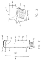
- FIG. 3 is an enlarged, perspective illustration of dovetail section 40 shown in the blade of FIG. 2 according to one embodiment of the present invention.
- dovetail section 40 comprises a straight axial entry dovetail that engages a mating slot defined in the turbine rotor wheel 18 (shown in FIG. 1 ).
- the straight axial entry dovetail includes a four hook design having eight contact surfaces configured to engage with turbine rotor wheel 18 (shown in FIG. 1 ).
- the straight axial entry dovetail is preferable in order to obtain a distribution of average and local stresses, protection during over-speed conditions and adequate low cycle fatigue (LCF) margins, as well as accommodate airfoil root section 44.
- FIG. 1 is an enlarged, perspective illustration of dovetail section 40 shown in the blade of FIG. 2 according to one embodiment of the present invention.
- dovetail section 40 comprises a straight axial entry dovetail that engages a mating slot defined in the turbine rotor wheel 18 (shown in FIG. 1 ).
- dovetail section 40 has a dovetail axial width 43 that in one embodiment can range from about 7.0 inches (17.78 centimeters) to about 16.8 inches (42.67 centimeters), with 7.0 inches (17.78 centimeters) being the preferred width.
- Dovetail section 40 also includes a groove 41 of about 360 degrees that holds a lock wire to maintain the axial position of blade 20. Those skilled in the art will recognize that the straight axial entry dovetail can have more or less than four hooks.
- FIG. 3 also shows an enlarged view of a transition area where the dovetail section 40 projects from the root section 44.
- FIG. 3 shows a fillet radius 58 at the location where root section 44 transitions to a platform 60 of dovetail section 40.
- FIG. 4 shows a perspective side illustration having an enlarged view of cover 48 depicted in FIG. 2 according to one embodiment of the present invention.
- cover 48 has a first portion 52 that overhangs pressure side 30 of the airfoil portion 42 and a second portion 54 that overhangs suction side 32 of airfoil portion 42.
- First portion 52 has a length that is substantially larger than a length of second portion 54.
- Cover 48 is positioned at an angle with respect to tip section 46. In one embodiment, the angle ranges from about 15 degrees to about 35 degrees, with 31.98 degrees being a preferred angle.
- FIG. 4 also shows that cover 48 extends from leading edge 34 of blade 20 to a location 62 along tip section 46 that is a predetermined distance away from trailing edge 36 of blade 20.
- a seal strip 64 extends from leading edge 34 of blade to location 62 along tip section 46 that is a predetermined distance away from trailing edge 36 of the blade 20. Seal strip 64 is designed to reduce steam leakage at tip section 46.
- FIG. 4 also shows that first portion 52 of cover 48 includes a non-contact surface 66 that is configured to be free of contact with adjacent covers in the stage of steam turbine blades and second portion 54 of cover 48 has a contact surface 68 that is configured to have contact with adjacent covers in a stage of steam turbine blades.
- FIG. 5 is a perspective illustration showing the interrelation of adjacent covers 48 according to one embodiment of the present invention.
- covers 48 are designed to have a gap 70 at non-contact surfaces 66 between adjacent covers and contact at contact surfaces 68, during initial assembly and/or at zero speed conditions.
- gap 70 can range from about 0.005 inches (0.127 millimeters) to about 0.015 inches (0.381 millimeters).
- turbine rotor wheel 18 shown in FIG. 1
- blades 20 begin to untwist.
- the interlocking cover provide improved blade stiffness, improved blade damping, and improved sealing at the outer radial positions of blades 20.
- the operating level for blades 20 is 3600 RPM, however, those skilled in the art will appreciate that the teachings herein are applicable to various scales of this nominal size. For example, one skilled in the art could scale the operating level by a scale factors such as 1.2, 2 and 2.4, to produce blades that operate at 3000 RPM, 1800 RPM and 1500 RPM, respectively.
- the blade 20 is preferably used in an L1 stage of a low pressure section of a steam turbine. However, the blade could also be used in other stages or other sections (e.g., high or intermediate) as well.
- one preferred blade length for blade 20 is about 20.4 inches (51.82 centimeters). This blade length can provide an L1 stage exit annulus area of about 43.14 ft 2 (4.0 m 2 ). This enlarged and improved exit annulus area can decrease the loss of kinetic energy the steam experiences as it leaves the L1 blades. This lower loss provides increased turbine efficiency.
Landscapes
- Engineering & Computer Science (AREA)
- Mechanical Engineering (AREA)
- General Engineering & Computer Science (AREA)
- Turbine Rotor Nozzle Sealing (AREA)
Applications Claiming Priority (1)
| Application Number | Priority Date | Filing Date | Title |
|---|---|---|---|
| US12/205,937 US8052393B2 (en) | 2008-09-08 | 2008-09-08 | Steam turbine rotating blade for a low pressure section of a steam turbine engine |
Publications (2)
| Publication Number | Publication Date |
|---|---|
| EP2161413A2 true EP2161413A2 (fr) | 2010-03-10 |
| EP2161413A3 EP2161413A3 (fr) | 2013-12-25 |
Family
ID=41350658
Family Applications (1)
| Application Number | Title | Priority Date | Filing Date |
|---|---|---|---|
| EP09168978.6A Withdrawn EP2161413A3 (fr) | 2008-09-08 | 2009-08-28 | Pale rotative de turbine à vapeur pour une section à faible pression d'un moteur de turbine à vapeur |
Country Status (4)
| Country | Link |
|---|---|
| US (1) | US8052393B2 (fr) |
| EP (1) | EP2161413A3 (fr) |
| JP (1) | JP2010065689A (fr) |
| RU (1) | RU2009133264A (fr) |
Cited By (1)
| Publication number | Priority date | Publication date | Assignee | Title |
|---|---|---|---|---|
| EP2322761A3 (fr) * | 2009-11-12 | 2013-10-09 | General Electric Company | Pale de turbine et rotor |
Family Cites Families (39)
| Publication number | Priority date | Publication date | Assignee | Title |
|---|---|---|---|---|
| GB2030657B (en) | 1978-09-30 | 1982-08-11 | Rolls Royce | Blade for gas turbine engine |
| US4767273A (en) * | 1987-02-24 | 1988-08-30 | Westinghouse Electric Corp. | Apparatus and method for reducing blade flop in steam turbine |
| US5067876A (en) | 1990-03-29 | 1991-11-26 | General Electric Company | Gas turbine bladed disk |
| DE4132332A1 (de) | 1990-12-14 | 1992-06-25 | Ottomar Gradl | Anordnung zum befestigen von schaufeln an der scheibe eines rotors |
| US5277549A (en) | 1992-03-16 | 1994-01-11 | Westinghouse Electric Corp. | Controlled reaction L-2R steam turbine blade |
| US5299915A (en) | 1992-07-15 | 1994-04-05 | General Electric Corporation | Bucket for the last stage of a steam turbine |
| US5267834A (en) | 1992-12-30 | 1993-12-07 | General Electric Company | Bucket for the last stage of a steam turbine |
| US5480285A (en) | 1993-08-23 | 1996-01-02 | Westinghouse Electric Corporation | Steam turbine blade |
| US5393200A (en) | 1994-04-04 | 1995-02-28 | General Electric Co. | Bucket for the last stage of turbine |
| US5494408A (en) | 1994-10-12 | 1996-02-27 | General Electric Co. | Bucket to wheel dovetail design for turbine rotors |
| US5531569A (en) | 1994-12-08 | 1996-07-02 | General Electric Company | Bucket to wheel dovetail design for turbine rotors |
| JP3178327B2 (ja) | 1996-01-31 | 2001-06-18 | 株式会社日立製作所 | 蒸気タービン |
| WO1999013200A1 (fr) * | 1997-09-05 | 1999-03-18 | Hitachi, Ltd. | Turbine a vapeur |
| JP4051132B2 (ja) * | 1998-05-25 | 2008-02-20 | 株式会社東芝 | タービン動翼 |
| US6142737A (en) | 1998-08-26 | 2000-11-07 | General Electric Co. | Bucket and wheel dovetail design for turbine rotors |
| JP3793667B2 (ja) | 1999-07-09 | 2006-07-05 | 株式会社日立製作所 | 低圧蒸気タービン最終段動翼の製造方法 |
| US6568908B2 (en) | 2000-02-11 | 2003-05-27 | Hitachi, Ltd. | Steam turbine |
| US6435833B1 (en) | 2001-01-31 | 2002-08-20 | General Electric Company | Bucket and wheel dovetail connection for turbine rotors |
| US6435834B1 (en) | 2001-01-31 | 2002-08-20 | General Electric Company | Bucket and wheel dovetail connection for turbine rotors |
| JP4316168B2 (ja) | 2001-08-30 | 2009-08-19 | 株式会社東芝 | 蒸気タービン動翼の翼材料および形状の選定方法と蒸気タービン |
| US6846160B2 (en) | 2001-10-12 | 2005-01-25 | Hitachi, Ltd. | Turbine bucket |
| US6652237B2 (en) | 2001-10-15 | 2003-11-25 | General Electric Company | Bucket and wheel dovetail design for turbine rotors |
| US6877956B2 (en) * | 2002-12-23 | 2005-04-12 | General Electric Company | Methods and apparatus for integral radial leakage seal |
| US6814543B2 (en) | 2002-12-30 | 2004-11-09 | General Electric Company | Method and apparatus for bucket natural frequency tuning |
| US6851926B2 (en) * | 2003-03-07 | 2005-02-08 | General Electric Company | Variable thickness turbine bucket cover and related method |
| EP1462610A1 (fr) * | 2003-03-28 | 2004-09-29 | Siemens Aktiengesellschaft | Série d'aubes de rotor pour turbomachines |
| US6893216B2 (en) | 2003-07-17 | 2005-05-17 | General Electric Company | Turbine bucket tip shroud edge profile |
| WO2005026501A1 (fr) * | 2003-09-10 | 2005-03-24 | Hitachi, Ltd. | Aube de rotor de turbine |
| US7001152B2 (en) * | 2003-10-09 | 2006-02-21 | Pratt & Wiley Canada Corp. | Shrouded turbine blades with locally increased contact faces |
| US7905709B2 (en) | 2004-02-10 | 2011-03-15 | General Electric Company | Advanced firtree and broach slot forms for turbine stage 1 and 2 buckets and rotor wheels |
| US7097428B2 (en) | 2004-06-23 | 2006-08-29 | General Electric Company | Integral cover bucket design |
| US7195455B2 (en) | 2004-08-17 | 2007-03-27 | General Electric Company | Application of high strength titanium alloys in last stage turbine buckets having longer vane lengths |
| US7632072B2 (en) * | 2005-12-29 | 2009-12-15 | Rolls-Royce Power Engineering Plc | Third stage turbine airfoil |
| US20070292265A1 (en) | 2006-06-14 | 2007-12-20 | General Electric Company | System design and cooling method for LP steam turbines using last stage hybrid bucket |
| US8038404B2 (en) | 2007-07-16 | 2011-10-18 | Nuovo Pignone Holdings, S.P.A. | Steam turbine and rotating blade |
| US7946823B2 (en) * | 2007-07-16 | 2011-05-24 | Nuovo Pignone Holdings, S.P.A. | Steam turbine rotating blade |
| US7946822B2 (en) * | 2007-07-16 | 2011-05-24 | Nuovo Pignone Holdings, S.P.A. | Steam turbine rotating blade |
| US8100657B2 (en) * | 2008-09-08 | 2012-01-24 | General Electric Company | Steam turbine rotating blade for a low pressure section of a steam turbine engine |
| US8075272B2 (en) * | 2008-10-14 | 2011-12-13 | General Electric Company | Steam turbine rotating blade for a low pressure section of a steam turbine engine |
-
2008
- 2008-09-08 US US12/205,937 patent/US8052393B2/en active Active
-
2009
- 2009-08-28 EP EP09168978.6A patent/EP2161413A3/fr not_active Withdrawn
- 2009-09-04 JP JP2009204187A patent/JP2010065689A/ja active Pending
- 2009-09-07 RU RU2009133264/06A patent/RU2009133264A/ru not_active Application Discontinuation
Cited By (1)
| Publication number | Priority date | Publication date | Assignee | Title |
|---|---|---|---|---|
| EP2322761A3 (fr) * | 2009-11-12 | 2013-10-09 | General Electric Company | Pale de turbine et rotor |
Also Published As
| Publication number | Publication date |
|---|---|
| US20100061842A1 (en) | 2010-03-11 |
| RU2009133264A (ru) | 2011-03-20 |
| JP2010065689A (ja) | 2010-03-25 |
| EP2161413A3 (fr) | 2013-12-25 |
| US8052393B2 (en) | 2011-11-08 |
Similar Documents
| Publication | Publication Date | Title |
|---|---|---|
| US8075272B2 (en) | Steam turbine rotating blade for a low pressure section of a steam turbine engine | |
| US8100657B2 (en) | Steam turbine rotating blade for a low pressure section of a steam turbine engine | |
| US8096775B2 (en) | Steam turbine rotating blade for a low pressure section of a steam turbine engine | |
| EP2161409B1 (fr) | Pale rotative de turbine à vapeur pour une section à faible pression d'une turbine à vapeur | |
| EP2199543B1 (fr) | Aube de rotor de turbine à gaz et procédé de conception d'une telle aube | |
| EP2820279B1 (fr) | Aube de turbomachine | |
| EP2959108B1 (fr) | Turbine à gaz ayant un étage désaccordé | |
| EP2743453B1 (fr) | Carénage de longueur de pièce conique | |
| US9328619B2 (en) | Blade having a hollow part span shroud | |
| US7946823B2 (en) | Steam turbine rotating blade | |
| US10273976B2 (en) | Actively morphable vane | |
| EP3084139B1 (fr) | Rotor aubagé monobloc de moteur à turbine à gaz comprenant des filets de tranchées asymétriques | |
| EP2236755A2 (fr) | Aube de rotor de turbine à vapeur avec entretoise intermediaire pour une application à basse pression | |
| CN105229262A (zh) | 叶片系统和制造叶片系统的对应方法 | |
| US7946822B2 (en) | Steam turbine rotating blade | |
| EP2738351A1 (fr) | Aube de turbine avec amortisseur de vibrations en forme de goutte d'eau localisé sur la hauteur de l'aube | |
| US7946821B2 (en) | Steam turbine rotating blade | |
| US8052393B2 (en) | Steam turbine rotating blade for a low pressure section of a steam turbine engine | |
| EP3358134B1 (fr) | Turbine à vapeur avec aube rotorique | |
| EP3409892B1 (fr) | Pale de turbine à gaz comprenant des ailettes pour compenser des forces centrifugales | |
| EP2997230B1 (fr) | Section conique de collet de pied d'aube tangentielle | |
| US7946820B2 (en) | Steam turbine rotating blade |
Legal Events
| Date | Code | Title | Description |
|---|---|---|---|
| PUAI | Public reference made under article 153(3) epc to a published international application that has entered the european phase |
Free format text: ORIGINAL CODE: 0009012 |
|
| AK | Designated contracting states |
Kind code of ref document: A2 Designated state(s): AT BE BG CH CY CZ DE DK EE ES FI FR GB GR HR HU IE IS IT LI LT LU LV MC MK MT NL NO PL PT RO SE SI SK SM TR |
|
| PUAL | Search report despatched |
Free format text: ORIGINAL CODE: 0009013 |
|
| AK | Designated contracting states |
Kind code of ref document: A3 Designated state(s): AT BE BG CH CY CZ DE DK EE ES FI FR GB GR HR HU IE IS IT LI LT LU LV MC MK MT NL NO PL PT RO SE SI SK SM TR |
|
| RIC1 | Information provided on ipc code assigned before grant |
Ipc: F01D 5/22 20060101AFI20131115BHEP |
|
| 17P | Request for examination filed |
Effective date: 20140625 |
|
| RBV | Designated contracting states (corrected) |
Designated state(s): AT BE BG CH CY CZ DE DK EE ES FI FR GB GR HR HU IE IS IT LI LT LU LV MC MK MT NL NO PL PT RO SE SI SK SM TR |
|
| 17Q | First examination report despatched |
Effective date: 20140725 |
|
| GRAP | Despatch of communication of intention to grant a patent |
Free format text: ORIGINAL CODE: EPIDOSNIGR1 |
|
| INTG | Intention to grant announced |
Effective date: 20161124 |
|
| STAA | Information on the status of an ep patent application or granted ep patent |
Free format text: STATUS: THE APPLICATION IS DEEMED TO BE WITHDRAWN |
|
| 18D | Application deemed to be withdrawn |
Effective date: 20170405 |