EP2161420A1 - Dispositif de purification de gaz d'échappement - Google Patents
Dispositif de purification de gaz d'échappement Download PDFInfo
- Publication number
- EP2161420A1 EP2161420A1 EP09151246A EP09151246A EP2161420A1 EP 2161420 A1 EP2161420 A1 EP 2161420A1 EP 09151246 A EP09151246 A EP 09151246A EP 09151246 A EP09151246 A EP 09151246A EP 2161420 A1 EP2161420 A1 EP 2161420A1
- Authority
- EP
- European Patent Office
- Prior art keywords
- channel
- exhaust gas
- coating layer
- purification device
- gas purification
- Prior art date
- Legal status (The legal status is an assumption and is not a legal conclusion. Google has not performed a legal analysis and makes no representation as to the accuracy of the status listed.)
- Granted
Links
Images



Classifications
-
- F—MECHANICAL ENGINEERING; LIGHTING; HEATING; WEAPONS; BLASTING
- F01—MACHINES OR ENGINES IN GENERAL; ENGINE PLANTS IN GENERAL; STEAM ENGINES
- F01N—GAS-FLOW SILENCERS OR EXHAUST APPARATUS FOR MACHINES OR ENGINES IN GENERAL; GAS-FLOW SILENCERS OR EXHAUST APPARATUS FOR INTERNAL-COMBUSTION ENGINES
- F01N3/00—Exhaust or silencing apparatus having means for purifying, rendering innocuous, or otherwise treating exhaust
- F01N3/02—Exhaust or silencing apparatus having means for purifying, rendering innocuous, or otherwise treating exhaust for cooling, or for removing solid constituents of, exhaust
- F01N3/021—Exhaust or silencing apparatus having means for purifying, rendering innocuous, or otherwise treating exhaust for cooling, or for removing solid constituents of, exhaust by means of filters
- F01N3/022—Exhaust or silencing apparatus having means for purifying, rendering innocuous, or otherwise treating exhaust for cooling, or for removing solid constituents of, exhaust by means of filters characterised by specially adapted filtering structure, e.g. honeycomb, mesh or fibrous
- F01N3/0222—Exhaust or silencing apparatus having means for purifying, rendering innocuous, or otherwise treating exhaust for cooling, or for removing solid constituents of, exhaust by means of filters characterised by specially adapted filtering structure, e.g. honeycomb, mesh or fibrous the structure being monolithic, e.g. honeycombs
-
- F—MECHANICAL ENGINEERING; LIGHTING; HEATING; WEAPONS; BLASTING
- F01—MACHINES OR ENGINES IN GENERAL; ENGINE PLANTS IN GENERAL; STEAM ENGINES
- F01N—GAS-FLOW SILENCERS OR EXHAUST APPARATUS FOR MACHINES OR ENGINES IN GENERAL; GAS-FLOW SILENCERS OR EXHAUST APPARATUS FOR INTERNAL-COMBUSTION ENGINES
- F01N3/00—Exhaust or silencing apparatus having means for purifying, rendering innocuous, or otherwise treating exhaust
- F01N3/08—Exhaust or silencing apparatus having means for purifying, rendering innocuous, or otherwise treating exhaust for rendering innocuous
- F01N3/10—Exhaust or silencing apparatus having means for purifying, rendering innocuous, or otherwise treating exhaust for rendering innocuous by thermal or catalytic conversion of noxious components of exhaust
- F01N3/24—Exhaust or silencing apparatus having means for purifying, rendering innocuous, or otherwise treating exhaust for rendering innocuous by thermal or catalytic conversion of noxious components of exhaust characterised by constructional aspects of converting apparatus
- F01N3/28—Construction of catalytic reactors
-
- B—PERFORMING OPERATIONS; TRANSPORTING
- B01—PHYSICAL OR CHEMICAL PROCESSES OR APPARATUS IN GENERAL
- B01D—SEPARATION
- B01D53/00—Separation of gases or vapours; Recovering vapours of volatile solvents from gases; Chemical or biological purification of waste gases, e.g. engine exhaust gases, smoke, fumes, flue gases, aerosols
- B01D53/34—Chemical or biological purification of waste gases
- B01D53/92—Chemical or biological purification of waste gases of engine exhaust gases
- B01D53/94—Chemical or biological purification of waste gases of engine exhaust gases by catalytic processes
- B01D53/944—Simultaneously removing carbon monoxide, hydrocarbons or carbon making use of oxidation catalysts
-
- F—MECHANICAL ENGINEERING; LIGHTING; HEATING; WEAPONS; BLASTING
- F01—MACHINES OR ENGINES IN GENERAL; ENGINE PLANTS IN GENERAL; STEAM ENGINES
- F01N—GAS-FLOW SILENCERS OR EXHAUST APPARATUS FOR MACHINES OR ENGINES IN GENERAL; GAS-FLOW SILENCERS OR EXHAUST APPARATUS FOR INTERNAL-COMBUSTION ENGINES
- F01N3/00—Exhaust or silencing apparatus having means for purifying, rendering innocuous, or otherwise treating exhaust
- F01N3/02—Exhaust or silencing apparatus having means for purifying, rendering innocuous, or otherwise treating exhaust for cooling, or for removing solid constituents of, exhaust
- F01N3/021—Exhaust or silencing apparatus having means for purifying, rendering innocuous, or otherwise treating exhaust for cooling, or for removing solid constituents of, exhaust by means of filters
- F01N3/033—Exhaust or silencing apparatus having means for purifying, rendering innocuous, or otherwise treating exhaust for cooling, or for removing solid constituents of, exhaust by means of filters in combination with other devices
- F01N3/035—Exhaust or silencing apparatus having means for purifying, rendering innocuous, or otherwise treating exhaust for cooling, or for removing solid constituents of, exhaust by means of filters in combination with other devices with catalytic reactors
-
- F—MECHANICAL ENGINEERING; LIGHTING; HEATING; WEAPONS; BLASTING
- F01—MACHINES OR ENGINES IN GENERAL; ENGINE PLANTS IN GENERAL; STEAM ENGINES
- F01N—GAS-FLOW SILENCERS OR EXHAUST APPARATUS FOR MACHINES OR ENGINES IN GENERAL; GAS-FLOW SILENCERS OR EXHAUST APPARATUS FOR INTERNAL-COMBUSTION ENGINES
- F01N3/00—Exhaust or silencing apparatus having means for purifying, rendering innocuous, or otherwise treating exhaust
- F01N3/08—Exhaust or silencing apparatus having means for purifying, rendering innocuous, or otherwise treating exhaust for rendering innocuous
- F01N3/10—Exhaust or silencing apparatus having means for purifying, rendering innocuous, or otherwise treating exhaust for rendering innocuous by thermal or catalytic conversion of noxious components of exhaust
- F01N3/18—Exhaust or silencing apparatus having means for purifying, rendering innocuous, or otherwise treating exhaust for rendering innocuous by thermal or catalytic conversion of noxious components of exhaust characterised by methods of operation; Control
- F01N3/20—Exhaust or silencing apparatus having means for purifying, rendering innocuous, or otherwise treating exhaust for rendering innocuous by thermal or catalytic conversion of noxious components of exhaust characterised by methods of operation; Control specially adapted for catalytic conversion
- F01N3/206—Adding periodically or continuously substances to exhaust gases for promoting purification, e.g. catalytic material in liquid form, NOx reducing agents
- F01N3/2066—Selective catalytic reduction [SCR]
-
- F—MECHANICAL ENGINEERING; LIGHTING; HEATING; WEAPONS; BLASTING
- F01—MACHINES OR ENGINES IN GENERAL; ENGINE PLANTS IN GENERAL; STEAM ENGINES
- F01N—GAS-FLOW SILENCERS OR EXHAUST APPARATUS FOR MACHINES OR ENGINES IN GENERAL; GAS-FLOW SILENCERS OR EXHAUST APPARATUS FOR INTERNAL-COMBUSTION ENGINES
- F01N3/00—Exhaust or silencing apparatus having means for purifying, rendering innocuous, or otherwise treating exhaust
- F01N3/08—Exhaust or silencing apparatus having means for purifying, rendering innocuous, or otherwise treating exhaust for rendering innocuous
- F01N3/10—Exhaust or silencing apparatus having means for purifying, rendering innocuous, or otherwise treating exhaust for rendering innocuous by thermal or catalytic conversion of noxious components of exhaust
- F01N3/24—Exhaust or silencing apparatus having means for purifying, rendering innocuous, or otherwise treating exhaust for rendering innocuous by thermal or catalytic conversion of noxious components of exhaust characterised by constructional aspects of converting apparatus
-
- B—PERFORMING OPERATIONS; TRANSPORTING
- B01—PHYSICAL OR CHEMICAL PROCESSES OR APPARATUS IN GENERAL
- B01D—SEPARATION
- B01D2258/00—Sources of waste gases
- B01D2258/01—Engine exhaust gases
- B01D2258/012—Diesel engines and lean burn gasoline engines
-
- B—PERFORMING OPERATIONS; TRANSPORTING
- B01—PHYSICAL OR CHEMICAL PROCESSES OR APPARATUS IN GENERAL
- B01D—SEPARATION
- B01D53/00—Separation of gases or vapours; Recovering vapours of volatile solvents from gases; Chemical or biological purification of waste gases, e.g. engine exhaust gases, smoke, fumes, flue gases, aerosols
- B01D53/34—Chemical or biological purification of waste gases
- B01D53/92—Chemical or biological purification of waste gases of engine exhaust gases
- B01D53/94—Chemical or biological purification of waste gases of engine exhaust gases by catalytic processes
- B01D53/9459—Removing one or more of nitrogen oxides, carbon monoxide, or hydrocarbons by multiple successive catalytic functions; systems with more than one different function, e.g. zone coated catalysts
- B01D53/9477—Removing one or more of nitrogen oxides, carbon monoxide, or hydrocarbons by multiple successive catalytic functions; systems with more than one different function, e.g. zone coated catalysts with catalysts positioned on separate bricks, e.g. exhaust systems
-
- B—PERFORMING OPERATIONS; TRANSPORTING
- B01—PHYSICAL OR CHEMICAL PROCESSES OR APPARATUS IN GENERAL
- B01J—CHEMICAL OR PHYSICAL PROCESSES, e.g. CATALYSIS OR COLLOID CHEMISTRY; THEIR RELEVANT APPARATUS
- B01J35/00—Catalysts, in general, characterised by their form or physical properties
- B01J35/19—Catalysts containing parts with different compositions
-
- F—MECHANICAL ENGINEERING; LIGHTING; HEATING; WEAPONS; BLASTING
- F01—MACHINES OR ENGINES IN GENERAL; ENGINE PLANTS IN GENERAL; STEAM ENGINES
- F01N—GAS-FLOW SILENCERS OR EXHAUST APPARATUS FOR MACHINES OR ENGINES IN GENERAL; GAS-FLOW SILENCERS OR EXHAUST APPARATUS FOR INTERNAL-COMBUSTION ENGINES
- F01N2510/00—Surface coverings
- F01N2510/06—Surface coverings for exhaust purification, e.g. catalytic reaction
- F01N2510/068—Surface coverings for exhaust purification, e.g. catalytic reaction characterised by the distribution of the catalytic coatings
- F01N2510/0682—Surface coverings for exhaust purification, e.g. catalytic reaction characterised by the distribution of the catalytic coatings having a discontinuous, uneven or partially overlapping coating of catalytic material, e.g. higher amount of material upstream than downstream or vice versa
-
- F—MECHANICAL ENGINEERING; LIGHTING; HEATING; WEAPONS; BLASTING
- F01—MACHINES OR ENGINES IN GENERAL; ENGINE PLANTS IN GENERAL; STEAM ENGINES
- F01N—GAS-FLOW SILENCERS OR EXHAUST APPARATUS FOR MACHINES OR ENGINES IN GENERAL; GAS-FLOW SILENCERS OR EXHAUST APPARATUS FOR INTERNAL-COMBUSTION ENGINES
- F01N2610/00—Adding substances to exhaust gases
- F01N2610/02—Adding substances to exhaust gases the substance being ammonia or urea
-
- Y—GENERAL TAGGING OF NEW TECHNOLOGICAL DEVELOPMENTS; GENERAL TAGGING OF CROSS-SECTIONAL TECHNOLOGIES SPANNING OVER SEVERAL SECTIONS OF THE IPC; TECHNICAL SUBJECTS COVERED BY FORMER USPC CROSS-REFERENCE ART COLLECTIONS [XRACs] AND DIGESTS
- Y02—TECHNOLOGIES OR APPLICATIONS FOR MITIGATION OR ADAPTATION AGAINST CLIMATE CHANGE
- Y02A—TECHNOLOGIES FOR ADAPTATION TO CLIMATE CHANGE
- Y02A50/00—TECHNOLOGIES FOR ADAPTATION TO CLIMATE CHANGE in human health protection, e.g. against extreme weather
- Y02A50/20—Air quality improvement or preservation, e.g. vehicle emission control or emission reduction by using catalytic converters
-
- Y—GENERAL TAGGING OF NEW TECHNOLOGICAL DEVELOPMENTS; GENERAL TAGGING OF CROSS-SECTIONAL TECHNOLOGIES SPANNING OVER SEVERAL SECTIONS OF THE IPC; TECHNICAL SUBJECTS COVERED BY FORMER USPC CROSS-REFERENCE ART COLLECTIONS [XRACs] AND DIGESTS
- Y02—TECHNOLOGIES OR APPLICATIONS FOR MITIGATION OR ADAPTATION AGAINST CLIMATE CHANGE
- Y02T—CLIMATE CHANGE MITIGATION TECHNOLOGIES RELATED TO TRANSPORTATION
- Y02T10/00—Road transport of goods or passengers
- Y02T10/10—Internal combustion engine [ICE] based vehicles
- Y02T10/12—Improving ICE efficiencies
Definitions
- the present invention relates to an exhaust gas purification device, and more particularly to an exhaust gas purification device in which a coating structure thereof is improved so as to sustain its normal purification efficiency.
- the exhaust system of an engine exhausts exhaust gas to a rear of a vehicle and reduces exhaust noise.
- a catalyst device has been used so as to purify the exhaust gas and transform harmful exhaust gas to harmless carbon dioxide and water.
- the catalyst device reduces hydrocarbon, carbon monoxide, and nitrogen oxide (NOx). Also, the catalyst device filters or burns particulate materials.
- a catalyst filter mounted in the exhaust gas purification device has channels that are formed in a flow direction of the exhaust gas.
- the inlet of at least one among the channels is closed and the outlet thereof is opened
- the inlet of at least another one among the channels is closed and the outlet thereof is opened
- the closed portions are alternatively disposed.
- a catalytic particulate filter (CPF) among the catalyst devices is applied, wherein the particulate materials (PM) bum to be transformed to soot therein.
- the soot is trapped and accumulated inside the catalytic particulate filter (CPF) such that the generating amount of NO2 is reduced and NOx purification efficiency of a selective catalyst reduction device is also reduced.
- CPF catalytic particulate filter
- Various aspects of the present invention are directed to provide an exhaust gas purification device having advantages of preventing a generation amount of NO2 from being reduced and improving NOx purification efficiency of a selective catalyst reduction device.
- an exhaust gas purification device that includes a catalytic particulate filter, in which a plurality of channels are formed in a flow direction of exhaust gas, inlet of at least one among the channels is closed and outlet thereof is opened, inlet of at least another one among the channels is closed and outlet thereof is opened, and the closed portions are alternatively disposed, may include a first coating layer of which a catalyst is coated to be formed on an interior surface of the channel in a direction from the inlet to the outlet as long as a predetermined first length, and/or a second coating layer of which the catalyst is coated to be formed on an exterior surface of the channel in a direction from the outlet to the inlet as long as a predetermined second length, wherein the catalyst is not coated on an interior surface of a downstream side of the channel.
- the outlet of the channel may be closed by a plug, a third coating layer of which the catalyst is coated is formed in outside surface of the plug, and the third coating layer is connected to the second coating layer.
- a selective catalytic reducing device may be mounted at a downstream side of the catalytic particulate filter.
- a reducing agent supply device may be mounted between the catalytic particulate filter and the selective catalytic reducing device.
- a diesel oxidation catalyst device may be disposed at an upstream side of the catalytic particulate filter.
- the exhaust gas channel may include a first channel and a second channel being laterally coupled each other and fluidly communicating therebetween through lateral contact surface thereof, wherein the exhaust gas is inlet through inlet opening of the first channel and outlet through lower portion of the first channel and/or outlet opening of the second channel, and wherein a first coating layer is formed on an interior surface of the first channel in a longitudinal direction thereof substantially from the inlet opening in a first predetermined length, the first coating layer being coated with a catalyst, and a second coating layer is formed on an interior surface of the second channel in a longitudinal direction thereof substantially from the outlet opening in a second predetermined length, the second coating layer being coated with the catalyst.
- the first and second coating layers may not be overlapped each other.
- the second coating layer may be further formed on an outer surface of the lower portion of the first channel in the longitudinal direction thereof substantially from a distal end portion thereof in the second predetermined length.
- the first and second coating layers may not be overlapped in each other.
- the inlet opening of the first channel may be wider than a distal end portion of the first channel.
- a distal end portion of the first channel may be closed.
- the distal end portion of the first channel may be closed by a plug.
- a third coating layer of which the catalyst is coated may be formed in outside surface of the plug.
- the distal end portion of the first channel may be closed by a plug, a third coating layer of which the catalyst is coated may be formed in outside surface of the plug, and the third coating layer may be connected to the second coating layer.
- a distal end portion of the second channel may be closed.
- the distal end portion of the second channel may be closed by a plug.
- the outlet opening of the second channel may be narrower than a distal end portion of the second channel.
- FIG. 1 is a perspective view of an exemplary exhaust gas purification device according to the present invention.
- FIG. 2 is a partial sectional detailed view of an exemplary catalytic particulate filter (CPF) according to the present invention.
- CPF catalytic particulate filter
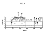
- FIG. 3 is a graph showing exhaust gas condition at an exemplary downstream side of catalytic particulate filter according to the present invention.
- FIG. 4 is a table showing exhaust gas condition when a catalytic particulate filter according to an exemplary embodiment of the present invention is used.
- FIG. 1 is a perspective view of an exhaust gas purification device according to various embodiments of the present invention.
- an exhaust gas purification system includes a diesel oxidation catalyst device 100, a catalytic particulate filter 105, a reducing agent supply device 110, and a selective catalytic reducing device 115.
- the diesel oxidation catalyst device (DOC) 100 is disposed at a downstream side of an engine so as to transform harmful gas (CO, THC, NOx, PM) to harmless gas (H2O, CO2).
- the catalytic particulate filter (CPF) 105 is disposed at a downstream side of the diesel oxidation catalyst device 100 so as to purify nitrogen oxide (NOx) and particulate matter (PM) including soot and smoke that is included in the exhaust gas.
- NOx nitrogen oxide
- PM particulate matter
- the catalytic particulate filter 105 oxidizes NO to NO2 to also improve the performance of the selective catalytic reducing device (115, SCR).
- the reducing agent supply device (DM: dosing module) 110 injects a reducing agent (e.g., an urea aqueous solution) so as to reduce NOx, and the selective catalytic reducing device (115) uses the reducing agent to reduce nitrogen oxide (NOx).
- a reducing agent e.g., an urea aqueous solution
- the selective catalytic reducing device (115) uses the reducing agent to reduce nitrogen oxide (NOx).
- NOx nitrogen oxide
- the structure and function of the purification devices 100, 105, 110, and 115 are well known to a person skilled in the art, so a detailed description thereof will be omitted.
- the catalyst coating structure of the catalytic particulate filter 105 is improved to increase the NO2 amount in the exhaust gas and to improve the function of the selective catalytic reducing device 115 and purifying rate of the nitrogen oxide (NOx).
- the improved coating structure of the catalytic particulate filter 105 sustains the purification efficiency, even though the soot and smoke is accumulated in the filter.
- the interior structure of the catalytic particulate filter 105 will be explained referring to FIG. 2 .
- FIG. 2 is a partial sectional detailed view of a catalytic particulate filter (CPF) according to various embodiments of the present invention.
- CPF catalytic particulate filter
- the catalytic particulate filter 105 includes a first cell plate 225, a second cell plate 230, and a third cell plate 240 that are sequentially disposed from an upper portion to a lower portion to face each other.
- the channel section shape of the catalytic particulate filter can be formed as a square, a hexagon, a circle, a triangle, and so on.
- the first and second cell plates 225 and 230 constitute the channel of the catalytic particulate filter, and this embodiment of the present invention is only an example and can be varied in a variety of types.
- An inlet 200 through which the exhaust gas flows into is formed in a front portion of the first and second cell plates 225 and 230, and plugs 245 and 235 are respectively disposed at the front and rear portions of the second and third cell plates 230 and 240.
- the exhaust gas flows into the channel that is formed between the first and second cell plates 225 and 230 through the inlet 200, moves from the left to the right in the drawing, penetrates the first and second cell plates 225 and 230, passes the outside path of the first cell plate 225 or the outside path of the second cell plate 230, and is discharged through the outlet 205.
- a first coating layer 210 in which catalyst is coated, is formed on the interior surface of the first and second cell plates 225 and 230, and the first coating layer 210 is formed in a direction from the inlet 200 to the plug 235 as long as a predetermined length. Further, a coating layer is not formed at a downstream side of the interior of the first and second cell plates 225 and 230.
- the soot and smoke (220) are trapped at a downstream side of the channel interior, wherein the catalyst is not coated at a downstream side of the interior surface of the channel such that the catalyst function is not deteriorated.
- a second coating layer 215, on which catalyst is coated is formed at a downstream side of the exterior surface of the first cell plate 225 and the second cell plates 230.
- the exhaust gas flows along the interior path at an upstream side of the channel that is formed between first and second cell plates 225 and 230, penetrates the first and second cell plates 225 and 230, and flows along the exterior path of the first and second cell plates 225 and 230 as it goes to the downstream portion such that the second coating layer 215 efficiently purifies the exhaust gas.
- a third coating layer 217 in which catalyst is coated, is further formed at the outside surface of the plug 235 to substantially improve the efficiency of the catalyst. As shown in FIG. 2 , it is desirable that the second coating layer 215 and the third coating layer 217 are connected to each other.
- CPF catalytic particulate filter
- the inlet and the outlet of the channels are alternatively closed by the plugs, the entire section thereof has a check pattern, and the exhaust gas penetrates through the cell plate (cell wall).
- particulate materials are trapped at the cell plate (cell wall) of the channel inside, and the exhaust gas is oxidized or reduced by the catalyst coating layer to be transformed to the harmless material and flows to a downstream side of the channel.
- the particulate material is increased, the flow resistance of the exhaust gas is increased.
- the particulate materials are burned at time intervals to be eliminated so as to resolve the problem.
- filters in the catalytic particulate filters are a honeycomb type, and the type can be varied according to design specifications.
- opening of the inlet 200 may be wider than the inner portion the plug 235 is disposed.
- the flow resistance of the exhaust gas at the upstream side of the catalytic particulate filter 105 may be increased since the pressure at the middle portion of the channel is increased so that the contact time period of the exhaust gas with the first coating layer 210 at the upstream side thereof may be elongated.
- opening of the outlet 206 may be narrower than the inner portion the plug 245 is disposed.
- the flow resistance of the exhaust gas at the downstream side of the catalytic particulate filter 105 may be increased so as to elongate the contact time period of the exhaust gas with the second coating layer 215.
- FIG. 3 is a graph showing exhaust gas condition at a downstream side of the catalytic particulate filter according to various embodiments of the present invention.
- the horizontal axis shows driving time and the vertical axis shows changing rate, wherein the NO2 generating amount 305 of the downstream side of the catalytic particulate filter 105 and the NOx purifying rate 300 of the selective catalytic reducing device 115 are graphed.
- the NO2 generating amount 305 that is supplied to the selective catalytic reducing device 115 is uniformly sustained so that the NOx purifying rate 300 can be uniformly maintained.
- the catalyst amount that is used in the catalytic particulate filter 105 is not increased and the NO2 generating amount 305 is maintained in a condition in which the soot 220 is trapped in the channel such that the effect thereof is demonstrated.
- FIG. 4 is a table showing exhaust gas condition when using a catalytic particulate filter according to various embodiments of the present invention.
- FIG. 4 it shows that the NO2 generation rate increases by 10% and the NOx purification efficiency increase by more than 15% in a condition in which the soot 220 is trapped in various embodiments of the present invention.
- the coating area of the catalyst is not reduced such that the generation amount of No2 is not reduced and the purification efficiency of NOx is improved in the exhaust gas purification device according to the present invention. Further, since the catalyst is coated at a downstream side of the outside surface of the channel instead of being coated at a downstream side of the inside surface of the channel, so the generation of NO2 is not reduced and the purification efficiency of NOx is improved.
Landscapes
- Engineering & Computer Science (AREA)
- Chemical & Material Sciences (AREA)
- Chemical Kinetics & Catalysis (AREA)
- Combustion & Propulsion (AREA)
- General Engineering & Computer Science (AREA)
- Mechanical Engineering (AREA)
- Health & Medical Sciences (AREA)
- Toxicology (AREA)
- Biomedical Technology (AREA)
- Environmental & Geological Engineering (AREA)
- Analytical Chemistry (AREA)
- General Chemical & Material Sciences (AREA)
- Oil, Petroleum & Natural Gas (AREA)
- Exhaust Gas After Treatment (AREA)
- Exhaust Gas Treatment By Means Of Catalyst (AREA)
Applications Claiming Priority (1)
| Application Number | Priority Date | Filing Date | Title |
|---|---|---|---|
| KR1020080087821A KR101028548B1 (ko) | 2008-09-05 | 2008-09-05 | 배기가스 정화장치 |
Publications (2)
| Publication Number | Publication Date |
|---|---|
| EP2161420A1 true EP2161420A1 (fr) | 2010-03-10 |
| EP2161420B1 EP2161420B1 (fr) | 2013-11-06 |
Family
ID=40886609
Family Applications (1)
| Application Number | Title | Priority Date | Filing Date |
|---|---|---|---|
| EP09151246.7A Ceased EP2161420B1 (fr) | 2008-09-05 | 2009-01-23 | Dispositif de purification de gaz d'échappement |
Country Status (4)
| Country | Link |
|---|---|
| US (1) | US8080208B2 (fr) |
| EP (1) | EP2161420B1 (fr) |
| KR (1) | KR101028548B1 (fr) |
| CN (1) | CN101664640A (fr) |
Cited By (6)
| Publication number | Priority date | Publication date | Assignee | Title |
|---|---|---|---|---|
| GB2481057A (en) * | 2010-06-11 | 2011-12-14 | Johnson Matthey Plc | Exhaust system comprising a catalyst with a downstream filter and SCR catalyst |
| US8940259B2 (en) | 2012-10-31 | 2015-01-27 | Johnson Matthey Public Limited Company | Catalysed soot filter |
| EP2832963A1 (fr) * | 2013-07-29 | 2015-02-04 | Mitsubishi Jidosha Kogyo Kabushiki Kaisha | Dispositif de purification de gaz d'échappement pour moteur à combustion interne |
| EP3207990A4 (fr) * | 2014-10-16 | 2017-11-15 | Cataler Corporation | Catalyseur pour purification des gaz d'échappement |
| US10344655B2 (en) | 2014-10-16 | 2019-07-09 | Cataler Corporation | Exhaust gas purification catalyst |
| FR3094648A1 (fr) * | 2019-04-08 | 2020-10-09 | Renault Sas | Filtre a particules catalyse pour moteur a combustion interne a allumage commande |
Families Citing this family (19)
| Publication number | Priority date | Publication date | Assignee | Title |
|---|---|---|---|---|
| JP4990379B2 (ja) * | 2010-03-30 | 2012-08-01 | 日本碍子株式会社 | 目封止ハニカム構造体、及びその製造方法 |
| US8845974B2 (en) | 2010-11-24 | 2014-09-30 | Basf Corporation | Advanced catalyzed soot filters and method of making and using the same |
| JP6158832B2 (ja) * | 2012-12-03 | 2017-07-05 | トヨタ自動車株式会社 | 排気浄化フィルタ |
| KR101360161B1 (ko) | 2013-01-17 | 2014-02-12 | 가부시키가이샤 고마쓰 세이사쿠쇼 | 환원제 수용액 믹싱 장치 및 이것을 구비한 배기 가스 후처리 장치 |
| JP5728578B2 (ja) | 2013-01-17 | 2015-06-03 | 株式会社小松製作所 | 還元剤水溶液ミキシング装置およびこれを備えた排気ガス後処理装置 |
| US8991160B2 (en) | 2013-01-17 | 2015-03-31 | Komatsu Ltd. | Reductant aqueous solution mixing device and exhaust aftertreatment device provided with the same |
| USD704227S1 (en) * | 2013-06-18 | 2014-05-06 | Komatsu Ltd. | Fluid-mixing device for a catalytic converter |
| USD702736S1 (en) * | 2013-06-18 | 2014-04-15 | Komatsu Ltd. | Fluid-mixing device for a catalytic converter |
| US20160032874A1 (en) * | 2014-07-29 | 2016-02-04 | Hyundai Motor Company | Diesel particulate filter (dpf) |
| CN107073377B (zh) | 2014-09-03 | 2021-02-26 | 康宁股份有限公司 | 具有活性堵塞物的废气过滤器 |
| WO2016036779A1 (fr) | 2014-09-03 | 2016-03-10 | Corning Incorporated | Corps en nid d'abeilles comprenant des bouchons en couches et son procédé de fabrication |
| EP3277402A4 (fr) * | 2015-03-30 | 2018-12-12 | BASF Corporation | Filtres catalysés avec revêtement d'extrémité pour moteur à mélange pauvre |
| DE102016110527A1 (de) | 2016-06-08 | 2017-12-14 | Dr. Ing. H.C. F. Porsche Aktiengesellschaft | Partikelfilter für eine Verbrennungskraftmaschine |
| JP6407349B1 (ja) * | 2017-05-11 | 2018-10-17 | 株式会社キャタラー | 排ガス浄化触媒装置 |
| EP3501648B1 (fr) | 2017-12-19 | 2023-10-04 | Umicore Ag & Co. Kg | Filtre à particules catalityquement actif |
| EP3505245B1 (fr) * | 2017-12-19 | 2019-10-23 | Umicore Ag & Co. Kg | Filtre à particules à effet catalytique actif |
| EP3505246B1 (fr) | 2017-12-19 | 2019-10-23 | Umicore Ag & Co. Kg | Filtre à particules à effet catalityque actif |
| CN112004599A (zh) * | 2018-08-22 | 2020-11-27 | 三井金属矿业株式会社 | 废气净化用催化剂 |
| WO2020200398A1 (fr) | 2019-03-29 | 2020-10-08 | Umicore Ag & Co. Kg | Filtre à particules à activité catalytique |
Citations (10)
| Publication number | Priority date | Publication date | Assignee | Title |
|---|---|---|---|---|
| EP0736503A1 (fr) * | 1995-04-05 | 1996-10-09 | Nippondenso Co., Ltd. | Filtre pour la purification de gaz d'échappement et procédé de production de celui-ci |
| US20030140620A1 (en) * | 2002-01-29 | 2003-07-31 | Ford Global Technologies, Inc. | Method of treating diesel exhaust gases |
| FR2849670A1 (fr) | 2003-01-07 | 2004-07-09 | Peugeot Citroen Automobiles Sa | Filtre a particules pour ligne d'echappement d'un moteur a combustion interne et ligne d'echappement le comprenant |
| US20040175315A1 (en) * | 1999-08-13 | 2004-09-09 | Brisley Robert James | Catalytic wall-flow filter |
| US20040254073A1 (en) * | 2003-06-11 | 2004-12-16 | Ming Wei | Multiple washcoats on filter substrate |
| US20050044844A1 (en) * | 2003-08-29 | 2005-03-03 | Berriman Lester P. | Upgraded emissions reduction system |
| FR2879236A1 (fr) | 2004-12-09 | 2006-06-16 | Renault Sas | Filtre a particules a section de canaux variable |
| DE102005013707A1 (de) | 2005-03-24 | 2006-09-28 | Daimlerchrysler Ag | Kraftfahrzeug mit Brennkraftmaschine und Verfahren zum Betreiben einer Brennkraftmaschine |
| WO2007034630A1 (fr) * | 2005-09-22 | 2007-03-29 | Nissan Diesel Motor Co., Ltd. | Dispositif d’epuration des gaz d’echappement |
| EP1892396A1 (fr) | 2006-08-16 | 2008-02-27 | Man Nutzfahrzeuge Ag | Système de traitement de gaz d'échappement |
Family Cites Families (5)
| Publication number | Priority date | Publication date | Assignee | Title |
|---|---|---|---|---|
| DE10003816A1 (de) * | 2000-01-28 | 2001-08-02 | Opel Adam Ag | Regenerierbarer Partikelfilter zum Entfernen von Rußpartikeln aus Abgasen |
| US7107763B2 (en) * | 2002-03-29 | 2006-09-19 | Hitachi Metals, Ltd. | Ceramic honeycomb filter and exhaust gas-cleaning method |
| JP4172986B2 (ja) * | 2002-10-10 | 2008-10-29 | 日本碍子株式会社 | ハニカム構造体及びその製造方法並びに当該ハニカム構造体を用いた排ガス浄化システム |
| JP3611213B2 (ja) * | 2003-02-07 | 2005-01-19 | 日立金属株式会社 | セラミックハニカム構造体 |
| US7722829B2 (en) * | 2004-09-14 | 2010-05-25 | Basf Catalysts Llc | Pressure-balanced, catalyzed soot filter |
-
2008
- 2008-09-05 KR KR1020080087821A patent/KR101028548B1/ko not_active Expired - Fee Related
-
2009
- 2009-01-22 US US12/357,953 patent/US8080208B2/en active Active
- 2009-01-23 EP EP09151246.7A patent/EP2161420B1/fr not_active Ceased
- 2009-02-20 CN CN200910007662A patent/CN101664640A/zh active Pending
Patent Citations (10)
| Publication number | Priority date | Publication date | Assignee | Title |
|---|---|---|---|---|
| EP0736503A1 (fr) * | 1995-04-05 | 1996-10-09 | Nippondenso Co., Ltd. | Filtre pour la purification de gaz d'échappement et procédé de production de celui-ci |
| US20040175315A1 (en) * | 1999-08-13 | 2004-09-09 | Brisley Robert James | Catalytic wall-flow filter |
| US20030140620A1 (en) * | 2002-01-29 | 2003-07-31 | Ford Global Technologies, Inc. | Method of treating diesel exhaust gases |
| FR2849670A1 (fr) | 2003-01-07 | 2004-07-09 | Peugeot Citroen Automobiles Sa | Filtre a particules pour ligne d'echappement d'un moteur a combustion interne et ligne d'echappement le comprenant |
| US20040254073A1 (en) * | 2003-06-11 | 2004-12-16 | Ming Wei | Multiple washcoats on filter substrate |
| US20050044844A1 (en) * | 2003-08-29 | 2005-03-03 | Berriman Lester P. | Upgraded emissions reduction system |
| FR2879236A1 (fr) | 2004-12-09 | 2006-06-16 | Renault Sas | Filtre a particules a section de canaux variable |
| DE102005013707A1 (de) | 2005-03-24 | 2006-09-28 | Daimlerchrysler Ag | Kraftfahrzeug mit Brennkraftmaschine und Verfahren zum Betreiben einer Brennkraftmaschine |
| WO2007034630A1 (fr) * | 2005-09-22 | 2007-03-29 | Nissan Diesel Motor Co., Ltd. | Dispositif d’epuration des gaz d’echappement |
| EP1892396A1 (fr) | 2006-08-16 | 2008-02-27 | Man Nutzfahrzeuge Ag | Système de traitement de gaz d'échappement |
Cited By (8)
| Publication number | Priority date | Publication date | Assignee | Title |
|---|---|---|---|---|
| GB2481057A (en) * | 2010-06-11 | 2011-12-14 | Johnson Matthey Plc | Exhaust system comprising a catalyst with a downstream filter and SCR catalyst |
| US8940259B2 (en) | 2012-10-31 | 2015-01-27 | Johnson Matthey Public Limited Company | Catalysed soot filter |
| EP2832963A1 (fr) * | 2013-07-29 | 2015-02-04 | Mitsubishi Jidosha Kogyo Kabushiki Kaisha | Dispositif de purification de gaz d'échappement pour moteur à combustion interne |
| EP3207990A4 (fr) * | 2014-10-16 | 2017-11-15 | Cataler Corporation | Catalyseur pour purification des gaz d'échappement |
| US10159935B2 (en) | 2014-10-16 | 2018-12-25 | Cataler Corporation | Exhaust gas purification catalyst |
| US10344655B2 (en) | 2014-10-16 | 2019-07-09 | Cataler Corporation | Exhaust gas purification catalyst |
| FR3094648A1 (fr) * | 2019-04-08 | 2020-10-09 | Renault Sas | Filtre a particules catalyse pour moteur a combustion interne a allumage commande |
| EP3738661A1 (fr) * | 2019-04-08 | 2020-11-18 | Renault S.A.S. | Filtre a particules catalyse pour moteur a combustion interne a allumage commande |
Also Published As
| Publication number | Publication date |
|---|---|
| EP2161420B1 (fr) | 2013-11-06 |
| KR101028548B1 (ko) | 2011-04-11 |
| KR20100028878A (ko) | 2010-03-15 |
| US8080208B2 (en) | 2011-12-20 |
| CN101664640A (zh) | 2010-03-10 |
| US20100058745A1 (en) | 2010-03-11 |
Similar Documents
| Publication | Publication Date | Title |
|---|---|---|
| US8080208B2 (en) | Exhaust gas purification device | |
| CN102057139B (zh) | 排放气体净化装置及排放气体净化系统 | |
| JP5173308B2 (ja) | 排気浄化装置 | |
| CN100371564C (zh) | 带有涂覆的纤维层的颗粒陷阱 | |
| JP4286887B2 (ja) | 排気浄化装置 | |
| US8066787B2 (en) | Bypass flow filter with improved filter efficiency and exhaust system and vehicle having the filter | |
| JP2009085065A (ja) | 排気浄化装置 | |
| JP4462556B2 (ja) | 内燃機関の排気浄化装置 | |
| US10107162B2 (en) | Catalyst subassembly, device comprising same for purifying exhaust gases from an internal combustion engine, modular system for the subassembly, and method for manufacturing the subassembly | |
| US8470253B2 (en) | Exhaust flow distribution device | |
| JP2007040149A (ja) | 内燃機関の排気浄化装置 | |
| US20140134062A1 (en) | Exhaust gas purification system of vehicle | |
| US8845973B2 (en) | Particle filter with hydrolysis coating, device and motor vehicle | |
| WO2014192183A1 (fr) | Dispositif de purification de gaz d'échappement | |
| JP4651560B2 (ja) | 内燃機関の排気浄化装置 | |
| US20110126525A1 (en) | Novel scr catalysts and after-treatment devices for diesel engine exhaust gas | |
| CN104704215A (zh) | 柴油发动机的废气净化装置 | |
| KR20140028730A (ko) | S-dpf 및 이를 구비한 배기시스템 | |
| CN113847123A (zh) | 车辆及其尾气后处理系统 | |
| CN106471230A (zh) | 用于燃烧式发动机的排放气体后处理装置 | |
| JP4680103B2 (ja) | 内燃機関の排気浄化装置 | |
| JP5470808B2 (ja) | 排気ガス浄化システムと排気ガス浄化方法 | |
| CN107035468A (zh) | 催化颗粒过滤器 | |
| JP6326580B2 (ja) | NOx還元触媒手段を備えた排気ガス浄化装置 | |
| US20100139261A1 (en) | Exhaust Gas Filter System |
Legal Events
| Date | Code | Title | Description |
|---|---|---|---|
| PUAI | Public reference made under article 153(3) epc to a published international application that has entered the european phase |
Free format text: ORIGINAL CODE: 0009012 |
|
| AK | Designated contracting states |
Kind code of ref document: A1 Designated state(s): AT BE BG CH CY CZ DE DK EE ES FI FR GB GR HR HU IE IS IT LI LT LU LV MC MK MT NL NO PL PT RO SE SI SK TR |
|
| AX | Request for extension of the european patent |
Extension state: AL BA RS |
|
| 17P | Request for examination filed |
Effective date: 20100728 |
|
| 17Q | First examination report despatched |
Effective date: 20100923 |
|
| AKX | Designation fees paid |
Designated state(s): DE |
|
| RIC1 | Information provided on ipc code assigned before grant |
Ipc: F01N 3/022 20060101AFI20130129BHEP Ipc: F01N 3/035 20060101ALN20130129BHEP Ipc: F01N 3/20 20060101ALI20130129BHEP Ipc: B01D 53/94 20060101ALI20130129BHEP Ipc: B01J 35/04 20060101ALI20130129BHEP |
|
| GRAP | Despatch of communication of intention to grant a patent |
Free format text: ORIGINAL CODE: EPIDOSNIGR1 |
|
| INTG | Intention to grant announced |
Effective date: 20130524 |
|
| RIC1 | Information provided on ipc code assigned before grant |
Ipc: F01N 3/022 20060101AFI20130513BHEP Ipc: B01J 35/00 20060101ALI20130513BHEP Ipc: F01N 3/035 20060101ALN20130513BHEP Ipc: B01D 53/94 20060101ALI20130513BHEP Ipc: B01J 35/04 20060101ALI20130513BHEP Ipc: F01N 3/20 20060101ALI20130513BHEP |
|
| GRAS | Grant fee paid |
Free format text: ORIGINAL CODE: EPIDOSNIGR3 |
|
| GRAA | (expected) grant |
Free format text: ORIGINAL CODE: 0009210 |
|
| AK | Designated contracting states |
Kind code of ref document: B1 Designated state(s): DE |
|
| REG | Reference to a national code |
Ref country code: DE Ref legal event code: R096 Ref document number: 602009019828 Country of ref document: DE Effective date: 20140102 |
|
| REG | Reference to a national code |
Ref country code: DE Ref legal event code: R097 Ref document number: 602009019828 Country of ref document: DE |
|
| PLBE | No opposition filed within time limit |
Free format text: ORIGINAL CODE: 0009261 |
|
| STAA | Information on the status of an ep patent application or granted ep patent |
Free format text: STATUS: NO OPPOSITION FILED WITHIN TIME LIMIT |
|
| 26N | No opposition filed |
Effective date: 20140807 |
|
| REG | Reference to a national code |
Ref country code: DE Ref legal event code: R097 Ref document number: 602009019828 Country of ref document: DE Effective date: 20140807 |
|
| PGFP | Annual fee paid to national office [announced via postgrant information from national office to epo] |
Ref country code: DE Payment date: 20221220 Year of fee payment: 15 |
|
| P01 | Opt-out of the competence of the unified patent court (upc) registered |
Effective date: 20230527 |
|
| REG | Reference to a national code |
Ref country code: DE Ref legal event code: R119 Ref document number: 602009019828 Country of ref document: DE |
|
| PG25 | Lapsed in a contracting state [announced via postgrant information from national office to epo] |
Ref country code: DE Free format text: LAPSE BECAUSE OF NON-PAYMENT OF DUE FEES Effective date: 20240801 |
|
| PG25 | Lapsed in a contracting state [announced via postgrant information from national office to epo] |
Ref country code: DE Free format text: LAPSE BECAUSE OF NON-PAYMENT OF DUE FEES Effective date: 20240801 |