EP2161476A1 - Antriebsstrang für ein Kraftfahrzeug und zugehöriger Steuerungsprozess - Google Patents
Antriebsstrang für ein Kraftfahrzeug und zugehöriger Steuerungsprozess Download PDFInfo
- Publication number
- EP2161476A1 EP2161476A1 EP09169491A EP09169491A EP2161476A1 EP 2161476 A1 EP2161476 A1 EP 2161476A1 EP 09169491 A EP09169491 A EP 09169491A EP 09169491 A EP09169491 A EP 09169491A EP 2161476 A1 EP2161476 A1 EP 2161476A1
- Authority
- EP
- European Patent Office
- Prior art keywords
- gear
- clutch
- primary
- speed
- primary shaft
- Prior art date
- Legal status (The legal status is an assumption and is not a legal conclusion. Google has not performed a legal analysis and makes no representation as to the accuracy of the status listed.)
- Withdrawn
Links
Images


Classifications
-
- F—MECHANICAL ENGINEERING; LIGHTING; HEATING; WEAPONS; BLASTING
- F16—ENGINEERING ELEMENTS AND UNITS; GENERAL MEASURES FOR PRODUCING AND MAINTAINING EFFECTIVE FUNCTIONING OF MACHINES OR INSTALLATIONS; THERMAL INSULATION IN GENERAL
- F16H—GEARING
- F16H3/00—Toothed gearings for conveying rotary motion with variable gear ratio or for reversing rotary motion
- F16H3/02—Toothed gearings for conveying rotary motion with variable gear ratio or for reversing rotary motion without gears having orbital motion
- F16H3/08—Toothed gearings for conveying rotary motion with variable gear ratio or for reversing rotary motion without gears having orbital motion exclusively or essentially with continuously meshing gears, that can be disengaged from their shafts
- F16H3/12—Toothed gearings for conveying rotary motion with variable gear ratio or for reversing rotary motion without gears having orbital motion exclusively or essentially with continuously meshing gears, that can be disengaged from their shafts with means for synchronisation not incorporated in the clutches
-
- F—MECHANICAL ENGINEERING; LIGHTING; HEATING; WEAPONS; BLASTING
- F16—ENGINEERING ELEMENTS AND UNITS; GENERAL MEASURES FOR PRODUCING AND MAINTAINING EFFECTIVE FUNCTIONING OF MACHINES OR INSTALLATIONS; THERMAL INSULATION IN GENERAL
- F16H—GEARING
- F16H61/00—Control functions within control units of change-speed- or reversing-gearings for conveying rotary motion ; Control of exclusively fluid gearing, friction gearing, gearings with endless flexible members or other particular types of gearing
- F16H61/04—Smoothing ratio shift
- F16H61/0403—Synchronisation before shifting
-
- F—MECHANICAL ENGINEERING; LIGHTING; HEATING; WEAPONS; BLASTING
- F16—ENGINEERING ELEMENTS AND UNITS; GENERAL MEASURES FOR PRODUCING AND MAINTAINING EFFECTIVE FUNCTIONING OF MACHINES OR INSTALLATIONS; THERMAL INSULATION IN GENERAL
- F16H—GEARING
- F16H61/00—Control functions within control units of change-speed- or reversing-gearings for conveying rotary motion ; Control of exclusively fluid gearing, friction gearing, gearings with endless flexible members or other particular types of gearing
- F16H61/68—Control functions within control units of change-speed- or reversing-gearings for conveying rotary motion ; Control of exclusively fluid gearing, friction gearing, gearings with endless flexible members or other particular types of gearing specially adapted for stepped gearings
- F16H61/684—Control functions within control units of change-speed- or reversing-gearings for conveying rotary motion ; Control of exclusively fluid gearing, friction gearing, gearings with endless flexible members or other particular types of gearing specially adapted for stepped gearings without interruption of drive
- F16H61/688—Control functions within control units of change-speed- or reversing-gearings for conveying rotary motion ; Control of exclusively fluid gearing, friction gearing, gearings with endless flexible members or other particular types of gearing specially adapted for stepped gearings without interruption of drive with two inputs, e.g. selection of one of two torque-flow paths by clutches
-
- F—MECHANICAL ENGINEERING; LIGHTING; HEATING; WEAPONS; BLASTING
- F16—ENGINEERING ELEMENTS AND UNITS; GENERAL MEASURES FOR PRODUCING AND MAINTAINING EFFECTIVE FUNCTIONING OF MACHINES OR INSTALLATIONS; THERMAL INSULATION IN GENERAL
- F16H—GEARING
- F16H61/00—Control functions within control units of change-speed- or reversing-gearings for conveying rotary motion ; Control of exclusively fluid gearing, friction gearing, gearings with endless flexible members or other particular types of gearing
- F16H61/04—Smoothing ratio shift
- F16H61/0403—Synchronisation before shifting
- F16H2061/0411—Synchronisation before shifting by control of shaft brakes
-
- F—MECHANICAL ENGINEERING; LIGHTING; HEATING; WEAPONS; BLASTING
- F16—ENGINEERING ELEMENTS AND UNITS; GENERAL MEASURES FOR PRODUCING AND MAINTAINING EFFECTIVE FUNCTIONING OF MACHINES OR INSTALLATIONS; THERMAL INSULATION IN GENERAL
- F16H—GEARING
- F16H2306/00—Shifting
- F16H2306/40—Shifting activities
- F16H2306/48—Synchronising of new gear
-
- F—MECHANICAL ENGINEERING; LIGHTING; HEATING; WEAPONS; BLASTING
- F16—ENGINEERING ELEMENTS AND UNITS; GENERAL MEASURES FOR PRODUCING AND MAINTAINING EFFECTIVE FUNCTIONING OF MACHINES OR INSTALLATIONS; THERMAL INSULATION IN GENERAL
- F16H—GEARING
- F16H3/00—Toothed gearings for conveying rotary motion with variable gear ratio or for reversing rotary motion
- F16H3/006—Toothed gearings for conveying rotary motion with variable gear ratio or for reversing rotary motion power being selectively transmitted by parallel flow paths, e.g. dual clutch transmissions
Definitions
- the present invention relates to controlled gearboxes for vehicles. It also relates to a method of controlling such a box.
- a plurality of intermeshed pinion pairs each determine a forward gear ratio and each has a first pinion integral with one shaft and a second pinion rotatably mounted on another shaft.
- at least one claw sleeve is alternately in the coupled position to link in rotation one of the second pinions and its shaft and in the uncoupled position free to rotate relative to the second pinion.
- These claw sleeves are typically integrated in friction synchronizers that adjust the rotational speeds of the idler and the shaft to allow jaw clutch without shock. Such synchronizers are expensive, bulky, wear out and slow down the gear changes.
- a transmission assembly comprising a gearbox having two primary shafts and a double clutch provided with a first clutch capable of coupling one of the primary shafts to a motor and provided with a second clutch capable of coupling the clutch.
- Other primary shafts to the motor such friction synchronizers are tested by the drag torque of the double clutch and are therefore more voluminous and expensive that they must be robust.
- the present invention is intended to overcome the disadvantages of the prior art.
- the subject of the invention is a gearbox driven for a vehicle, particularly for a motor vehicle, characterized in that it comprises two primary shafts each of which can be coupled to a motor via a double clutch provided a first clutch that can couple one of the trees primary motor and a second clutch coupling the other of the primary shafts to the motor, a secondary shaft arranged to be rotatably connected to at least one drive wheel of the vehicle and a plurality of pairs of gear wheels each determining a gear ratio.
- gearing forward and each comprising a first pinion integral with one of the primary shafts and a second pinion rotatably mounted on the secondary shaft, at least one claw sleeve alternately in the coupled position by linking in rotation one of the second pinions and its shaft and in uncoupled position free to rotate relative to the second gear, a housing supporting the rotating shafts and a brake which is interposed between the housing and the primary shafts and which can occupy a neutral position in which a friction element of the brake connected to the housing is free to rotate relative to the primary shafts and two active positions in each of which s the brake couples one of the primary shafts to the crankcase by braking the primary shaft when the rotational speed of the latter must be lowered until reaching a target synchronization speed to synchronize the rotation speeds of the primary shaft and of the secondary shaft of a report to engage and allow the passage of the claw sleeve from its decoupled position to its coupled position by adjusting the speed of rotation of the second gear ratio to engage and the rotational speed of the claw s
- the subject of the invention is also a transmission assembly for a vehicle, in particular for a motor vehicle, comprising a gearbox and a clutch, characterized in that the gearbox is in accordance with the invention and that clutch is a double clutch provided with a first clutch can in a closed position couple one of the primary shafts to a motor and a second clutch can in a closed position couple the other primary shafts to the engine, each of clutches that can in an open position uncouple the motor and the associated primary shaft, which can occupy a friction position in which the clutch is partially closed and can be at the same time in a different position than the other one of the clutches.
- clutch is a double clutch provided with a first clutch can in a closed position couple one of the primary shafts to a motor and a second clutch can in a closed position couple the other primary shafts to the engine, each of clutches that can in an open position uncouple the motor and the associated primary shaft, which can occupy a friction position in which the clutch is partially closed and can be at the
- the invention also relates to a powertrain for a vehicle, particularly for a motor vehicle, comprising a motor, characterized in that it comprises a transmission assembly according to the invention in which each clutch of the double clutch can be in its closed position in which the speed of rotation of a disc of the clutch is identical to the speed of the engine, can be in its open position by making the rotation of the disc of the clutch independent of the engine speed and can be in its friction position allowing a variation of the speed of rotation of the disc of the clutch and the primary shaft associated with the clutch according to the engine speed while the jaw sleeves of the second gear meshing with the first pinions of said primary shaft are in the decoupled position.
- the method according to the invention comprises a step of direct interconnection of the claw sleeve and the second gear ratio to engage if the initial speed of the primary shaft bearing the first gear of the gear pair of the gear to engage is substantially equal to the target speed, while the clutch associated with the primary shaft bearing the first gear of the gear pair of the initial gear is closed, the brake is inactive and the clutch associated with the shaft primary bearing the first pinion report to engage is open.
- the method according to the invention comprises a clutch of the sleeve and the second gear ratio to engage at the end of the braking step and at the end of the clutch friction step.
- the method according to the invention comprises an acceleration of the engine speed.
- a motor vehicle generally comprises a power train 10 comprising a motor 12 and a gearbox 14 that can be coupled by a clutch 16.
- the pistons 20, the crankshaft 22 and the flywheel 24 are shown schematically in FIG. figure 1 .
- the clutch 16 is a double clutch provided with two clutches 26 and 28 each having a disc that can be engaged by being closed on an annular bearing surface belonging to a part 24 integral with the flywheel rotated by the crankshaft 22.
- the gearbox 14 comprises two primary shafts 36 and 38 respectively connected to rotation to the clutches 26 and 28.
- the first primary shaft 36 carries a gear 42 of the second gear ratio and a gear 44 of the fourth gear ratio, that is to say the gears of the even gear ratios of the gearbox 14.
- the second primary shaft 38 carries a pinion 51 of the first gear ratio, a pinion 53 of the third gear ratio and a pinion 55 of the fifth gear ratio, that is to say the gears of the odd gearbox ratios 14.
- the gearbox 14 comprises a secondary shaft 58 rotatably connected to the drive wheels of the vehicle by a box output shaft end 60 and secured to at least one element of a differential not shown.
- the secondary shaft 58 carries the idle gears of the gearbox meshing with the pinions 42, 44, 51, 53 and 55 carried by the primary shafts 36 and 38, namely the pinions 61, 62, 63, 64 and 65 belonging to respectively to the pair of gears of the first, second, third, fourth and fifth gears of the gearbox.
- the secondary shaft 58 carries axially sliding jaw sleeves.
- a jaw sleeve 67 is disposed between the idle gears 61 and 63 respectively of the first and third gears to be coupled thereto for transmitting torque from the secondary shaft 58 to said idle gears when said gears are engaged.
- a jaw sleeve 68 is disposed between the idle gears 62 and 64 respectively of the second and fourth gears.
- a jaw sleeve 69 is associated with the idler gear 65 of the fifth gear.
- the jaw sleeves 67, 68 and 69 do not belong to friction synchronizers, so that during gear changes, synchronization of the rotation of the secondary shaft carrying the jaw sleeves 67, 68, 69 with the rotation of the idle gears 61, 63, 62, 64 and 65 respectively engaged with the pinions 51, 53, 42, 44 and 55 integral with the primary shafts must be carried out other than by classically rubbing friction elements in a friction synchronizer .
- the synchronization during gear changes is performed using the clutches 26 and 28 of the double clutch 16 and a brake 70 which is interposed between a housing of the gearbox 14 and the primary shafts 36 and 38.
- the brake 70 comprises an axially fixed disk 72 integral with the first primary shaft 36 and an axially fixed disk 74 secured to the second primary shaft 38.
- a disk axially movable 76 can move coaxially with the primary shafts 36 and 38, this displacement being effected from the fixed disk 72 to the fixed disk 74.
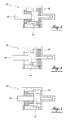
- the axially movable disc 76 slides relative to the gearbox housing and is fixed to rotate relative to said housing. It is mounted on the housing by means of a three-position actuator 80 ( Figures 3 to 5 ).
- Unrepresented control means such as a computer, control the automatic operation of the gearbox 14 by controlling the distributor of the actuator 80, the displacement of the clutch sleeves 67, 68, 69 and the double clutch 16.
- the primary shaft which is not under torque that is to say the primary shaft which is not coupled to the motor via the clutch associated with it
- the shifting sequences are detailed below in the three scenarios that can occur in a gear change, for example the change from the second gear to the third gear as shown in FIG. figure 6 , and in a downward change of gear, for example the transition from the third gear to the second gear as shown in figure 7 .
- the sleeve 68 Before a change in amount from the second report to the third report as shown in figure 6 , that is to say before the instant T1, the sleeve 68 is in position coupled to the pinion 62 and the clutch 26 associated with the first primary shaft 36 carrying the pinion 42 is closed since the transmission assembly must transmit the torque while driving on the second gear.
- the clutch 28 associated with the second primary shaft 38 is open while the jaw sleeves 67 and 69 of the odd ratios of the box are in the decoupled position relative to the gears 61, 63 and 65.
- the speed of the second input shaft 38 must be in accordance with a target speed which is dependent on the speed of the vehicle and the initial engine speed at the time T1 of the beginning of gear change taking into account the the reduction of the initial ratio and which is determined according to the gear ratio to engage, here the third ratio of the gearbox, and the speed that the vehicle is supposed to have at the end of the shift.
- the commitment of the target report here the third report
- the brake 70 is inactive, that is to say in the neutral position with its axially movable disk 76 placed between the fixed disks 72 and 74.
- the clutch 26 associated with the first primary shaft 36 can be closed because the dog sleeve 68 is in the decoupled position.
- the regime of the second primary shaft 38 at time T1 is close to the target regime.
- the clutching of the jaw sleeve 67 and the pinion 63 can then be performed between the instant T1 and the instant T2, while the clutch 26 associated with the first primary shaft 36 is closed, the clutch 28 associated with the second shaft primary 28 is open and the brake 70 is inactive.
- the clutch 26 associated with the first primary shaft 36 is open while the clutch sleeve 68 is placed in the decoupled position and secondly the clutch 28 associated with the second primary shaft 28 is closed.
- the clutch 26 associated with the first primary shaft 36 can be closed because the dog sleeve 68 is in the decoupled position.
- the regime of the second primary shaft 38 at time T1 is above the target regime. It is necessary that the clutch 28 associated with the second main shaft is open and it is necessary to slide or skate or rub the brake 70 by the action of the disk 76 on the disc 74 associated with the second primary shaft 38 to brake the idler gear 63 until it reaches, at time T2, a regime allowing interconnection given the gear ratio.
- the braking time is very short.
- the clutch of the jaw sleeve 67 and the pinion 63 being made, from the instant T2, the clutch 26 associated with the first primary shaft 36 can be opened while the clutch sleeve 68 is placed in the decoupled position.
- the clutch 28 associated with the second primary shaft 38 can be closed and the brake 70 is rendered inactive.
- the clutch 26 associated with the first primary shaft 36 can be closed because the dog sleeve 68 is in the decoupled position.
- Curve 94 of the figure 6 represents the engine speed which, in order to guarantee maximum discretion of the shift, continues to increase by maintaining its acceleration in a phase of acceleration of the vehicle during the gear change and decreasing at the end of the shift, between instants T3 and T4.
- the speed of the first primary shaft 36 must be in accordance with the target speed which is dependent on the speed of the vehicle and the initial engine speed at time T5 of start of gear change taking into account the reduction of the initial ratio and which is determined according to the gear ratio to engage, here the second ratio of the gearbox, and the speed that the vehicle is supposed to have at the end of the shift.
- the two clutches 26 and 28 of the double clutch 16 are moved to the open or disengaged state between times T5 and T6 to decouple the engine from the gearbox and, as shown on the curve 100 of the engine speed of the figure 7 , the engine speed is increased at so-called accelerated speed in a first time interval between times T5 and T6, then the engine is kept accelerated to have its target speed at the end of the gear change.
- the clutch 26 associated with the first primary shaft 36 is closed or engaged, and between the instant T8 and the instant T9 end of shifting, the engine speed is adjusted according to the inertia of the power train and the load setpoint given to the engine to get the target speed.
- the clutch 28 associated with the second primary shaft 38 can be closed again after sleeve 67 of the initial report is in the decoupled position, its closure being for example actuated between times T8 and T9 to avoid any shock in the gearbox.
- the brake 70 is inactive.
- the speed of the first primary shaft 36 at the initial time T5 is close to the target speed.
- the clutching of the claw sleeve 68 and the pinion 62 can then be performed from time T6, while the clutches are open, the engine is at the accelerated speed close to the target speed. After the interconnection, the operation is consistent with that of the first case when the clutch is performed, the brake being inactive.
- the brake variant shown in figure 2 differs from the embodiment of the brake shown in figure 1 by a movable stirrup 110 which replaces the movable disc 76.
- the stirrup 110 comprises a first flange 112 whose inner face is provided to rub on the axially fixed disc 72 and a second flange 114 whose inner face is provided to rub on the axially fixed disc 74.
- the stirrup 110 is integral with the rod 86 of the actuator 80 and moves axially according to the pressure exerted on one side or the other of the piston.
- the gearbox according to the invention comprises two secondary shafts instead of one, to allow a bulk of the different box or to add reports.
- the actuator is a magnetic suction cup or a linear electromagnetic actuator instead of being a hydraulic actuator.
Landscapes
- Engineering & Computer Science (AREA)
- General Engineering & Computer Science (AREA)
- Mechanical Engineering (AREA)
- Control Of Transmission Device (AREA)
- Structure Of Transmissions (AREA)
Applications Claiming Priority (1)
| Application Number | Priority Date | Filing Date | Title |
|---|---|---|---|
| FR0855998A FR2935770B1 (fr) | 2008-09-08 | 2008-09-08 | Boite de vitesses pilotee pour vehicule |
Publications (1)
| Publication Number | Publication Date |
|---|---|
| EP2161476A1 true EP2161476A1 (de) | 2010-03-10 |
Family
ID=40279837
Family Applications (1)
| Application Number | Title | Priority Date | Filing Date |
|---|---|---|---|
| EP09169491A Withdrawn EP2161476A1 (de) | 2008-09-08 | 2009-09-04 | Antriebsstrang für ein Kraftfahrzeug und zugehöriger Steuerungsprozess |
Country Status (2)
| Country | Link |
|---|---|
| EP (1) | EP2161476A1 (de) |
| FR (1) | FR2935770B1 (de) |
Cited By (4)
| Publication number | Priority date | Publication date | Assignee | Title |
|---|---|---|---|---|
| WO2012049402A1 (fr) | 2010-10-11 | 2012-04-19 | Renault S.A.S. | Boite de vitesses compacte a six pignons et double embrayage |
| WO2012056136A1 (fr) | 2010-10-28 | 2012-05-03 | Peugeot Citroën Automobiles SA | Systeme de commande pour une boite de vitesses de type a commande automatisee pour un vehicule |
| WO2013000830A1 (de) * | 2011-06-30 | 2013-01-03 | Avl List Gmbh | Doppelkupplungsgetriebe für ein fahrzeug und verfahren zum betreiben eines solchen getriebes |
| WO2015163805A1 (en) * | 2014-04-23 | 2015-10-29 | Scania Cv Ab | Arrangement for an upshift process in a gearbox |
Families Citing this family (2)
| Publication number | Priority date | Publication date | Assignee | Title |
|---|---|---|---|---|
| FR2973091A1 (fr) * | 2011-03-23 | 2012-09-28 | Peugeot Citroen Automobiles Sa | Boite de vitesses pilotee pour vehicule a moteur |
| FR3018487B1 (fr) | 2014-03-14 | 2017-12-22 | Peugeot Citroen Automobiles Sa | Procede de controle, lors d'un changement de rapports, d'un groupe motopropulseur incluant une boite de vitesses automatisee |
Citations (2)
| Publication number | Priority date | Publication date | Assignee | Title |
|---|---|---|---|---|
| DE19950679A1 (de) * | 1999-10-21 | 2001-04-26 | Volkswagen Ag | Automatisiertes Doppelkupplungsgetriebe und Verfahren zur Steuerung eines automatisierten Doppelkupplungsgetriebes |
| US20040144190A1 (en) * | 2003-01-24 | 2004-07-29 | Arthur Hall | Seven-speed power transmission |
-
2008
- 2008-09-08 FR FR0855998A patent/FR2935770B1/fr not_active Expired - Fee Related
-
2009
- 2009-09-04 EP EP09169491A patent/EP2161476A1/de not_active Withdrawn
Patent Citations (2)
| Publication number | Priority date | Publication date | Assignee | Title |
|---|---|---|---|---|
| DE19950679A1 (de) * | 1999-10-21 | 2001-04-26 | Volkswagen Ag | Automatisiertes Doppelkupplungsgetriebe und Verfahren zur Steuerung eines automatisierten Doppelkupplungsgetriebes |
| US20040144190A1 (en) * | 2003-01-24 | 2004-07-29 | Arthur Hall | Seven-speed power transmission |
Cited By (4)
| Publication number | Priority date | Publication date | Assignee | Title |
|---|---|---|---|---|
| WO2012049402A1 (fr) | 2010-10-11 | 2012-04-19 | Renault S.A.S. | Boite de vitesses compacte a six pignons et double embrayage |
| WO2012056136A1 (fr) | 2010-10-28 | 2012-05-03 | Peugeot Citroën Automobiles SA | Systeme de commande pour une boite de vitesses de type a commande automatisee pour un vehicule |
| WO2013000830A1 (de) * | 2011-06-30 | 2013-01-03 | Avl List Gmbh | Doppelkupplungsgetriebe für ein fahrzeug und verfahren zum betreiben eines solchen getriebes |
| WO2015163805A1 (en) * | 2014-04-23 | 2015-10-29 | Scania Cv Ab | Arrangement for an upshift process in a gearbox |
Also Published As
| Publication number | Publication date |
|---|---|
| FR2935770A1 (fr) | 2010-03-12 |
| FR2935770B1 (fr) | 2011-07-29 |
Similar Documents
| Publication | Publication Date | Title |
|---|---|---|
| EP1977140B1 (de) | Antriebsstrang mit an einer ausgleichswelle des getriebes angeschlossenem hilfsmotor | |
| FR2935770A1 (fr) | Boite de vitesses pilotee pour vehicule | |
| EP1995494B1 (de) | Getriebe mit selbstausrückenden Klauen und Kupplungsverzweigung durch ein höheres Übersetzungsverhältnis und entsprechendes Schaltverfahren | |
| EP2138371A1 (de) | Verfahren zur Zusammenschaltung einer Elektromaschinenwelle mit einer Radwelle beim Elektro- oder Hybridfahrzeug | |
| EP4047235A1 (de) | Modul für ein system zur synchronisation und zum antrieb einer zwischenwelle eines getriebes | |
| WO2012107679A1 (fr) | Dispositif et procédé pour la commande d'une boite de vitesses a double embrayage | |
| FR2674928A1 (fr) | Dispositif de synchronisation des vitesses angulaires des arbres d'une boite de vitesses. | |
| EP2273154A1 (de) | Getriebe mit kupplungsverzweigung und entsprechendes Schaltverfahren | |
| FR2972516A1 (fr) | Procede de changement de rapport de vitesses sous couple sur une boite de vitesse a double embrayage, dispositif mettant en œuvre ce procede et vehicule incorporant un tel dispositif | |
| WO2021170523A1 (fr) | Module motorisé, sous-ensemble hybride d'entrainement d'un véhicule, et méthode d'engagement d'un crabot dans ledit sous-ensemble hybride | |
| FR2923569A1 (fr) | Vehicule a systeme de synchronisation d'une boite de vitesses pilotee et procede de commande du systeme de synchronisation. | |
| EP3117127B1 (de) | Steuerungsverfahren während eines gangwechsels eines antriebstrangs eines automatikgetriebes | |
| WO2021014061A1 (fr) | Système de transmission de puissance hybride à changement de rapport de vitesse synchonisé par un moteur électrique | |
| FR2850906A1 (fr) | Boite de vitesses pour vehicule automobile et procede de changement de rapport de vitesses mis en oeuvre au moyen d'une telle boite de vitesses | |
| FR3098452A1 (fr) | Dispositif de traction hybride de vehicule automobile a double chemin de puissance electrique | |
| FR2925945A1 (fr) | Systeme de synchronisation d'une boite de vitesses comportant un frein et vehicule equipe d'un tel systeme | |
| WO2011036394A1 (fr) | Dispositif de synchronisation et de solidarisation des arbres primaires d'une boite de vitesses a double embrayage | |
| FR2897134A1 (fr) | Groupe motopropulseur hybride optimise pour l'engagement de la premiere vitesse et de la marche arriere | |
| FR3081790A1 (fr) | Boite de vitesses a synchronisation centralisee | |
| FR2938620A1 (fr) | Systeme de synchronisation adapte a synchroniser un premier element tournant avec un deuxieme element pour ajuster la vitesse de rotation du premier element tournant a un regime cible | |
| EP1382890B1 (de) | Momentunterbrechung-begrenzendes Fahrzeuggetriebe | |
| FR3077536A1 (fr) | Dispositif de transmission a deux vitesses pour vehicule electrique | |
| FR2896564A1 (fr) | Boite de vitesses robotisee a deux actionneurs. | |
| FR2896559A1 (fr) | Boite de vitesses a couple de pignons de demultiplication monte sur un arbre intermediaire. | |
| EP1008782A1 (de) | Gangwechsel-Verfahren und Vorrichtung für Kraftfahrzeuge |
Legal Events
| Date | Code | Title | Description |
|---|---|---|---|
| PUAI | Public reference made under article 153(3) epc to a published international application that has entered the european phase |
Free format text: ORIGINAL CODE: 0009012 |
|
| AK | Designated contracting states |
Kind code of ref document: A1 Designated state(s): AT BE BG CH CY CZ DE DK EE ES FI FR GB GR HR HU IE IS IT LI LT LU LV MC MK MT NL NO PL PT RO SE SI SK SM TR |
|
| STAA | Information on the status of an ep patent application or granted ep patent |
Free format text: STATUS: THE APPLICATION IS DEEMED TO BE WITHDRAWN |
|
| 18D | Application deemed to be withdrawn |
Effective date: 20100911 |