EP2161920A2 - Système de portage de caméra pouvant être monté sur le corps, doté d'un assemblage multifonctionnel de composants électriques - Google Patents
Système de portage de caméra pouvant être monté sur le corps, doté d'un assemblage multifonctionnel de composants électriques Download PDFInfo
- Publication number
- EP2161920A2 EP2161920A2 EP09180794A EP09180794A EP2161920A2 EP 2161920 A2 EP2161920 A2 EP 2161920A2 EP 09180794 A EP09180794 A EP 09180794A EP 09180794 A EP09180794 A EP 09180794A EP 2161920 A2 EP2161920 A2 EP 2161920A2
- Authority
- EP
- European Patent Office
- Prior art keywords
- camera
- video
- connection
- signal
- video signal
- Prior art date
- Legal status (The legal status is an assumption and is not a legal conclusion. Google has not performed a legal analysis and makes no representation as to the accuracy of the status listed.)
- Granted
Links
- 230000002093 peripheral effect Effects 0.000 claims description 28
- 238000011156 evaluation Methods 0.000 claims description 5
- 230000011664 signaling Effects 0.000 claims description 4
- 230000005540 biological transmission Effects 0.000 abstract description 12
- 239000002131 composite material Substances 0.000 description 12
- 230000008054 signal transmission Effects 0.000 description 2
- 238000010276 construction Methods 0.000 description 1
Images
Classifications
-
- H—ELECTRICITY
- H04—ELECTRIC COMMUNICATION TECHNIQUE
- H04N—PICTORIAL COMMUNICATION, e.g. TELEVISION
- H04N5/00—Details of television systems
- H04N5/76—Television signal recording
- H04N5/765—Interface circuits between an apparatus for recording and another apparatus
- H04N5/77—Interface circuits between an apparatus for recording and another apparatus between a recording apparatus and a television camera
-
- F—MECHANICAL ENGINEERING; LIGHTING; HEATING; WEAPONS; BLASTING
- F16—ENGINEERING ELEMENTS AND UNITS; GENERAL MEASURES FOR PRODUCING AND MAINTAINING EFFECTIVE FUNCTIONING OF MACHINES OR INSTALLATIONS; THERMAL INSULATION IN GENERAL
- F16M—FRAMES, CASINGS OR BEDS OF ENGINES, MACHINES OR APPARATUS, NOT SPECIFIC TO ENGINES, MACHINES OR APPARATUS PROVIDED FOR ELSEWHERE; STANDS; SUPPORTS
- F16M13/00—Other supports for positioning apparatus or articles; Means for steadying hand-held apparatus or articles
- F16M13/04—Other supports for positioning apparatus or articles; Means for steadying hand-held apparatus or articles for supporting on, or holding steady relative to, a person, e.g. by chains, e.g. rifle butt or pistol grip supports, supports attached to the chest or head
-
- G—PHYSICS
- G03—PHOTOGRAPHY; CINEMATOGRAPHY; ANALOGOUS TECHNIQUES USING WAVES OTHER THAN OPTICAL WAVES; ELECTROGRAPHY; HOLOGRAPHY
- G03B—APPARATUS OR ARRANGEMENTS FOR TAKING PHOTOGRAPHS OR FOR PROJECTING OR VIEWING THEM; APPARATUS OR ARRANGEMENTS EMPLOYING ANALOGOUS TECHNIQUES USING WAVES OTHER THAN OPTICAL WAVES; ACCESSORIES THEREFOR
- G03B17/00—Details of cameras or camera bodies; Accessories therefor
- G03B17/56—Accessories
- G03B17/561—Support related camera accessories
-
- G—PHYSICS
- G03—PHOTOGRAPHY; CINEMATOGRAPHY; ANALOGOUS TECHNIQUES USING WAVES OTHER THAN OPTICAL WAVES; ELECTROGRAPHY; HOLOGRAPHY
- G03B—APPARATUS OR ARRANGEMENTS FOR TAKING PHOTOGRAPHS OR FOR PROJECTING OR VIEWING THEM; APPARATUS OR ARRANGEMENTS EMPLOYING ANALOGOUS TECHNIQUES USING WAVES OTHER THAN OPTICAL WAVES; ACCESSORIES THEREFOR
- G03B17/00—Details of cameras or camera bodies; Accessories therefor
- G03B17/56—Accessories
- G03B17/563—Camera grips, handles
-
- H—ELECTRICITY
- H04—ELECTRIC COMMUNICATION TECHNIQUE
- H04N—PICTORIAL COMMUNICATION, e.g. TELEVISION
- H04N5/00—Details of television systems
- H04N5/222—Studio circuitry; Studio devices; Studio equipment
-
- F—MECHANICAL ENGINEERING; LIGHTING; HEATING; WEAPONS; BLASTING
- F16—ENGINEERING ELEMENTS AND UNITS; GENERAL MEASURES FOR PRODUCING AND MAINTAINING EFFECTIVE FUNCTIONING OF MACHINES OR INSTALLATIONS; THERMAL INSULATION IN GENERAL
- F16M—FRAMES, CASINGS OR BEDS OF ENGINES, MACHINES OR APPARATUS, NOT SPECIFIC TO ENGINES, MACHINES OR APPARATUS PROVIDED FOR ELSEWHERE; STANDS; SUPPORTS
- F16M2200/00—Details of stands or supports
- F16M2200/04—Balancing means
Definitions
- the invention relates to a body-mountable camera vision system with a multifunctional composite of electrical components.
- Body mountable camera support systems are known and, for example, in EP 0 316 370 A1 described. With these camera-based systems, cameras, peripherals, and the batteries or rechargeable batteries required for power can be carried by a cameraman and kept stable regardless of the movements of the cameraman. To connect the camera, the peripherals and the power supply to each other usually several connections and wiring are available so that the appropriate connections can be made without the cameraman is hampered in his work.
- a body mountable camera system in which at least two connection devices with at least an additional signal line are connected, so that at one of the two terminal devices, a sensor device and at the other of the two terminal devices, a signaling device are wired connected.
- the connection takes place with the aid of the additional signal line in such a way that it can be used via the connection devices, but without the function or the use of the connection devices provided for other purposes being disturbed.
- connection device in addition to its main function is made possible.
- the signal of a tally sensor whose output signal indicates the tally lamp of a camera, and the driving signal for a tally signal generator, such as a tally LED, in this way via existing sockets, which provide an additional connection for The additional signal line are supplemented, are led, of course, usually only if the sockets are not used according to their main function.
- the invention can be used, for example, in a body-mountable camera vision system with a multifunctional composite of electrical components, namely: with at least one first connection device for the wired supply of a video signal from a camera, at least one second connection device for the wired supply of a video signal to a peripheral device, for example a monitor a video recording device and / or a transmission device for video signals, a plurality of signal lines for transmitting the video signals between the connection devices, and at least one operating mode switching device for switching the operating mode of the connection devices and the signal lines, wherein in a first operating mode a plurality of signal lines for the transmission of a video signal of a first type, for example a high-definition video signal (HDTV), and wherein in a second operating mode, a part of the plurality of signal lines for the transmission of a video signal of a second type, for example a low-resolution (analog) or digital (SDI) video signal, is usable and the remaining part of the plurality of signal lines is us
- the signal lines required for high-resolution video signals are also used in a meaningful way when the camera vision system according to the invention is used with an analog or a digital camera.
- the connections are designed accordingly and the required signal lines are available. If some signal lines are not required for the transmission of video signals, according to the invention, these lines are available for other uses and are used accordingly in other ways. This ensures that the camera vision system according to the invention over the known systems is more flexible, without an increased and in some cases unused effort is driven.
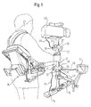
- Fig. 1 the construction of a body mountable camera support system is shown, in which according to the invention a multifunctional composite of electrical components can be provided.
- a bracket 21 On a bracket 21, a camera 22, a monitor 23 and batteries 24 and 25 are attached by way of example.
- the holding tube is connected to a support frame 26, with the help of which the cameraman carries the body mountable camera support system.
- connection housing 27 and 28 On the holding tube 21 further connection housing 27 and 28 are provided, on which connection sockets 31 to 38 are arranged.
- connection sockets 31 to 38 are provided, on which connection sockets 31 to 38 are arranged.
- These connectors provide the ability to connect electrical (video) connection cables 39 and 40 or electrical power cables 41 and 42 from the camera, monitor and batteries.
- Other peripherals such as video recorders or video signal transducers with appropriate connection cables, may also be connected to the receptacles.
- Between the sockets 31 to 38 extend signal and power supply lines mostly inside the tube 21.
- 27 and 28 electrical components can be accommodated
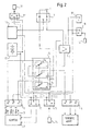
- Fig. 2 the inventive composite of electrical components of the body mountable camera support system is shown.
- a first connection device 1 for the wired supply of a video signal from a camera 2 is provided.
- the video signal from the camera 2 via a corresponding connection cable 3 to the first Terminal device 1 is supplied, may be a high-resolution or low-resolution (analog) video signal.
- a high-definition video signal HDTV
- three signal lines are needed.
- a low-resolution (analog) video signal conventionally only one signal line is used.
- other video signals for example digital video signals (SDI), can be fed via one or more video signal lines which are fed to the first connection device 1 from the camera 2 via the connection cable 3.
- SDI digital video signals
- a second connection device 4 for the wired supply of a video signal to a peripheral device is shown.
- the supplied video signal may be a high-resolution, a low-resolution (analog) or a digital video signal, so that a corresponding number of signal lines is needed.
- Peripheral devices are, for example, monitors, video recording devices or video signal transmission devices.
- a plurality of signal lines R, G, B are provided for the transmission of the video signals between the connection devices 1 and 4.
- the video signals are transmitted from the first terminal device 1 to the second terminal device 2 via an uninterrupted signal line, as shown for example for the signal line G; in part, the transmission of the video signals but also over several sections of the signal lines instead, as shown for the signal lines R and B.
- an operating mode switching device 5 which switches the combination of electrical components of the camera-based system according to the invention between two operating modes.
- a first operating mode for which the switching position of the switching device 5 is shown, the plurality of signal lines R, G and B are used for the transmission of a high-definition video signal (HDTV).
- HDTV high-definition video signal
- the video signal VideoR of the camera 2 is transmitted via the signal line R and thus via a first switching unit 5a and a second switching unit 5b to the second connection unit 4.
- the video signal VideoB of the camera 2 is transmitted via the signal line B and thus via the switching unit 5c to the second connection unit 4.
- the signal line G establishes a direct connection between the first connection device 1 and the second connection device 4, so that a transmission of the video signal G of the camera 2 is ensured.
- all video signals VideoR, VideoG and VideoB of a high-resolution video camera 2 are transmitted from the first connection device 1 to the second connection device 4.
- the low-resolution (analog) video signal of the camera 2 is supplied to the signal line R via the first connection device 1 and passes through the first switching unit 5a and other components, which are described in more detail below, to the second connection device 4.
- the video signal from the first switching unit 5a is supplied to a video amplifier / multiplexer 6, which amplifies the supplied video signal and distributed to a plurality of outputs.
- the video signal of a first output of the video amplifier / multiplexer 6 is supplied to a third terminal 7 for supplying video signals to peripheral devices.
- a video signal of the peripheral device can be guided by the third connection device 7 via the second switching unit 5b to the second connection device 4.
- the video signal of the first output of the video amplifier / multiplexer 6 is transmitted via a bridge 8 to the second connection device 4 via the second changeover unit 5b.
- any peripheral device for editing / changing the video signal which is supplied from the first output of the video amplifier / multiplexer 6 of the third terminal device 7, are connected, so that then changed from the third terminal device 7 from the peripheral device / edited video signal is supplied via the second switching unit 5 b to the second terminal device 4.
- the video signal of a second output of the video amplifier / multiplexer 6 is fed to a fourth connection device 9 for the wired supply of a video signal to a peripheral device.
- a further peripheral device can be connected to the inventive composite of electrical components of the camera support system in addition to the peripherals connected to the second and third terminal unit.
- additional peripheral device may be provided.
- the signal line B is used in the second operating mode in order to transmit a video signal from a third output of the video amplifier / multiplexer 6 via the third switching unit 5c to the first connection device 1.
- the inventive composite of electrical components preferably includes further connector devices 10, 11 and 12 connected to an electrical power supply unit 13 comprising one or more rechargeable batteries and those for the camera and the peripherals provide connections to a power supply.
- the other connection devices can, as in Fig. 2 shown, provide the same operating voltage or allow different operating voltages for the supply to the camera or to peripheral devices.
- an additional signal line is provided on at least one of the connection devices, which, beyond the standard assignment of the connection device and without obstructing it, offers the possibility of connecting a sensor device 14.
- the sensor device 14 is exemplified both in the fourth connection device 9 and in the further connection device 11.
- the signal of the sensor device 14 is in the in Fig. 2 shown embodiment via a signal line to an evaluation unit 15 which is connected via a further signal line to the connection means 7 and 12. Again, the signal is provided by the evaluation unit 15 in addition to the standard assignment of the connection devices 7 and 12.
- a signaling device 16 can be connected, which in Fig. 2 is shown by way of example at connection device 12.
- the state of a tally signal light of the camera detected and transmitted via the additional signal line to a signal generator 16 becomes.
- the usually not visible to the cameraman light state of the tally signal display is transmitted to another signal generator and can be provided on a better visible for the cameraman point of the camera support system.
- the sensor device is configured accordingly, it is possible to dispense with the evaluation unit 15, so that a single additional signal line has to be provided between the connection devices in order to enable the connection of the sensor and the signal transmitter.
- connection devices are preferably provided in duplicate, so that two connection sockets are provided for a connection function.
- this configuration is shown by way of example for the fourth connection device 9, which is additionally provided as the fifth connection device 9 '.
- connection boxes 27 and 28 can be made with short connecting cables a connection corresponding to the main function on one of the sockets, so a peripheral device to be connected, and an additional function on the other connector socket can be used.
- the invention is directed to a body-mountable camera vision system having a multifunctional composite of electrical components, namely, at least a first connector means for the cabled delivery of a video signal from a camera; at least one second connection device for the wired supply of a video signal to a peripheral device, for example a monitor, a video recording device and / or a transmission device for video signals; a plurality of signal lines for transmitting the video signals between the terminal devices; and at least one operating mode switching device for switching the operating mode of the connecting devices and the signal lines, wherein in a first operating mode, the plurality of signal lines for the transmission of a video signal of a first type are used and wherein in a second operating mode, a part of the plurality of signal lines for the transmission of a video signal of a second Type is usable and the remaining part of the plurality of signal lines is usable for other purposes.
- the camera vision system is characterized in that in the first operating mode, the plurality of signal lines establish a direct connection between the first and the second connection means.
- a third connection device for the wired supply of a video signal to a peripheral device is provided, which is supplied in the second operating mode, the video signal of a signal line of the plurality of signal lines and from which a video signal of the peripheral device of the second connection device is supplied.
- the camera vision system may be characterized in that in the second mode of operation, the video signal from a signal line of the plurality of signal lines is applied to an input of a video amplifier / multiplexer device, the video signal of a first output of the video amplifier / multiplexer device second connection means is supplied and the video signal of a second output of the video amplifier / multiplexer means a fourth connection means for the wired supply of a video signal is supplied to a peripheral device.
- the video signal of the first output of Video amplifier / multiplexer device supplied to the third terminal device, and the video signal from the third terminal device of the second terminal device is supplied.
- the camera vision system may be characterized in that in the second mode of operation, the video signal of a third output of the video amplifier / multiplexer means is supplied to the first terminal device via a signal line of the remaining part of the plurality of signal lines.
- At least one signal line of the plurality of signal lines runs without interruption between the first and second terminal devices.
- the camera vision system may further be characterized in that further connection devices are provided for the supply / distribution of electrical energy to the camera and / or to peripheral devices.
- At least one of the connection devices can be provided in duplicate.
- the camera image system can further be characterized in that at least two of the connection devices are connected to at least one additional signal line, so that one sensor device can be connected to one of the two connection devices and a signal transmission device can be connected to the other of the two connection devices.
Landscapes
- Engineering & Computer Science (AREA)
- Multimedia (AREA)
- Signal Processing (AREA)
- Physics & Mathematics (AREA)
- General Physics & Mathematics (AREA)
- General Engineering & Computer Science (AREA)
- Mechanical Engineering (AREA)
- Studio Devices (AREA)
- Accessories Of Cameras (AREA)
- Cameras In General (AREA)
- Camera Bodies And Camera Details Or Accessories (AREA)
Applications Claiming Priority (2)
| Application Number | Priority Date | Filing Date | Title |
|---|---|---|---|
| DE10145193A DE10145193C1 (de) | 2001-09-13 | 2001-09-13 | Körpermontierbares Kameratragesystem mit einem multifunktionalen Verbund elektrischer Komponenten |
| EP02772294A EP1425904B1 (fr) | 2001-09-13 | 2002-09-12 | Systeme de portage de camera pouvant etre monte sur le corps, dote d'un assemblage multifonctionnel de composants electriques |
Related Parent Applications (1)
| Application Number | Title | Priority Date | Filing Date |
|---|---|---|---|
| EP02772294.1 Division | 2002-09-12 |
Publications (3)
| Publication Number | Publication Date |
|---|---|
| EP2161920A2 true EP2161920A2 (fr) | 2010-03-10 |
| EP2161920A3 EP2161920A3 (fr) | 2010-03-31 |
| EP2161920B1 EP2161920B1 (fr) | 2011-02-16 |
Family
ID=7698932
Family Applications (2)
| Application Number | Title | Priority Date | Filing Date |
|---|---|---|---|
| EP09180794A Expired - Lifetime EP2161920B1 (fr) | 2001-09-13 | 2002-09-12 | Système de portage de caméra pouvant être monté sur le corps, doté d'un assemblage multifonctionnel de composants électriques |
| EP02772294A Expired - Lifetime EP1425904B1 (fr) | 2001-09-13 | 2002-09-12 | Systeme de portage de camera pouvant etre monte sur le corps, dote d'un assemblage multifonctionnel de composants electriques |
Family Applications After (1)
| Application Number | Title | Priority Date | Filing Date |
|---|---|---|---|
| EP02772294A Expired - Lifetime EP1425904B1 (fr) | 2001-09-13 | 2002-09-12 | Systeme de portage de camera pouvant etre monte sur le corps, dote d'un assemblage multifonctionnel de composants electriques |
Country Status (8)
| Country | Link |
|---|---|
| US (1) | US7646424B2 (fr) |
| EP (2) | EP2161920B1 (fr) |
| JP (1) | JP4164544B2 (fr) |
| AT (2) | ATE477671T1 (fr) |
| AU (1) | AU2002337088C1 (fr) |
| DE (3) | DE10145193C1 (fr) |
| ES (1) | ES2357922T3 (fr) |
| WO (1) | WO2003024093A1 (fr) |
Families Citing this family (6)
| Publication number | Priority date | Publication date | Assignee | Title |
|---|---|---|---|---|
| EP2836097B1 (fr) * | 2012-04-09 | 2017-06-07 | John Christopher Fawcett | Veste de support |
| CN104728581A (zh) * | 2013-12-19 | 2015-06-24 | 韩新宇 | 随身用载物架 |
| US20170108892A1 (en) * | 2015-10-14 | 2017-04-20 | Atomic Vr Inc | Wearable computing system |
| CN108374975A (zh) * | 2018-04-08 | 2018-08-07 | 李达 | 一种多功能悬挂式智能摄影机稳定系统 |
| CN113091641B (zh) * | 2021-04-07 | 2022-11-08 | 杭州迈平勘测规划设计咨询有限公司 | 手持激光扫描仪辅助装备 |
| USD1114046S1 (en) * | 2024-01-03 | 2026-02-17 | Easyrig AB | Body-worn camera stabilizer |
Citations (1)
| Publication number | Priority date | Publication date | Assignee | Title |
|---|---|---|---|---|
| EP0316370A1 (fr) | 1987-03-03 | 1989-05-24 | Sachtler Kommunikationstech | Support de camera a porter sur le corps. |
Family Cites Families (41)
| Publication number | Priority date | Publication date | Assignee | Title |
|---|---|---|---|---|
| US4017168A (en) * | 1974-09-16 | 1977-04-12 | Brown Garrett W | Equipment for use with hand held motion picture cameras |
| US4083480A (en) * | 1976-03-19 | 1978-04-11 | Ampex Corporation | Stabilizing apparatus for body-carried equipment |
| US4158490A (en) * | 1976-11-11 | 1979-06-19 | Panavision, Incorporated | Body-mounted support device for motion picture camera |
| US4298149A (en) * | 1978-01-17 | 1981-11-03 | Panavision, Incorporated | Body harness for cinematographer |
| US4206983A (en) * | 1978-08-25 | 1980-06-10 | Continental Camera Systems, Inc. | Camera stabilizing body mount |
| US4474439A (en) * | 1982-01-26 | 1984-10-02 | Brown Garrett W | Camera support |
| DE3504362C1 (de) | 1985-02-08 | 1986-06-12 | Sachtler GmbH Filmtechnische Geräte, 8046 Garching | Hoehenverstellbare Saeule,insbesondere Mittelsaeule fuer ein Stativ zur Aufnahme einer Film- oder Fernsehkamera |
| US4672436A (en) * | 1986-02-05 | 1987-06-09 | Louis Hawthorne | Integrated camcorder viewing and support system |
| US4946272A (en) * | 1988-09-22 | 1990-08-07 | Brown Garrett W | Stabilized equipment support, primarily for use with light-weight cameras |
| US5065249A (en) * | 1988-09-26 | 1991-11-12 | Vicon Industries, Inc. | Portable video camera/monitor support |
| US4991758A (en) * | 1989-09-22 | 1991-02-12 | Eaneff Charles S | Support system for portable video camera |
| USD329449S (en) * | 1990-03-21 | 1992-09-15 | Garrett W. Brown | Camera stabilizing support |
| JPH04264887A (ja) * | 1991-02-19 | 1992-09-21 | Sony Corp | プラグ装置 |
| JPH05207338A (ja) * | 1992-01-27 | 1993-08-13 | Matsushita Electric Ind Co Ltd | ビデオカメラの表示装置 |
| US5360196A (en) * | 1992-09-15 | 1994-11-01 | Garrett W. Brown | Adjustable, iso-elastic support apparatus |
| US5517338A (en) | 1992-10-20 | 1996-05-14 | Monsanto Company | Composite mirrors |
| FR2705152B1 (fr) | 1993-05-10 | 1995-08-04 | Meriaux Delbarre Romain | Equipement de prise de vues a distance, autonome. |
| JPH07107359A (ja) * | 1993-09-30 | 1995-04-21 | Canon Inc | 撮像装置 |
| US5323195A (en) * | 1993-10-21 | 1994-06-21 | Phillips Stephan D | Apparatus for supporting a camera |
| USD358832S (en) * | 1994-03-18 | 1995-05-30 | Garrett W. Brown | Camera support and stabilizing system |
| US5462214A (en) * | 1994-04-14 | 1995-10-31 | Buswell; Brian | Body mounted camera support assembly |
| US5821995A (en) * | 1994-12-23 | 1998-10-13 | Hitachi Denshi Kabushiki Kaisha | Method and apparatus for controlling transmission of multiplexed video signals |
| US5752112A (en) * | 1996-11-06 | 1998-05-12 | George Paddock, Inc. | Mounting system for body mounted camera equipment |
| JP3317176B2 (ja) * | 1997-02-06 | 2002-08-26 | 松下電器産業株式会社 | 映像伝送装置 |
| US5749010A (en) * | 1997-04-18 | 1998-05-05 | Mccumber Enterprises, Inc. | Camera support |
| JPH10304234A (ja) * | 1997-04-24 | 1998-11-13 | Sony Corp | 撮像システム、及びビデオカメラ装置 |
| US6437834B1 (en) * | 1998-05-27 | 2002-08-20 | Nec Corporation | Video switching and mix/effecting equipment |
| JP3223915B2 (ja) * | 1998-05-27 | 2001-10-29 | 日本電気株式会社 | 映像切替合成装置 |
| US6825875B1 (en) * | 1999-01-05 | 2004-11-30 | Interval Research Corporation | Hybrid recording unit including portable video recorder and auxillary device |
| EP1051037A3 (fr) * | 1999-05-04 | 2001-08-29 | Everest-VIT, Inc. (a New Jersey Corporation) | Procédé et système d'inspection |
| FI19992070A7 (fi) | 1999-09-28 | 2001-03-29 | Carbion Oy | Uudet fukosyloidut oligosakkaridit ja menetelmä niiden valmistamiseksi |
| CN100390178C (zh) | 1999-11-12 | 2008-05-28 | 拜奥根Idec马萨诸塞公司 | 作为腺苷受体拮抗剂的多环烷基嘌呤 |
| MY127897A (en) | 1999-12-13 | 2006-12-29 | Ppg Ind Ohio Inc | Polymerizable polyol(allyl carbonate) compositions |
| US6547456B2 (en) * | 2000-09-11 | 2003-04-15 | Wishoo, Inc. | Portable system for digital photo management |
| US6956614B1 (en) * | 2000-11-22 | 2005-10-18 | Bath Iron Works | Apparatus and method for using a wearable computer in collaborative applications |
| US6530702B2 (en) * | 2000-12-02 | 2003-03-11 | Thomas H. S. Harris | Operator supported remote camera positioning and control system |
| US7012203B2 (en) | 2001-09-07 | 2006-03-14 | Carl Zeiss Surgical Gmbh | Foot switch pedal controller for a surgical instrument |
| FR2829580B1 (fr) | 2001-09-07 | 2004-02-13 | Bio Merieux | Procede de lecture, de detection ou de quantification, hybrides ou complexes utilises dans ce procede et biopuce mettant en oeuvre ledit procede |
| DE10145198C1 (de) | 2001-09-13 | 2003-04-24 | Sachtler Gmbh & Co Kg | Kardanische Aufhängevorrichtung für eine Kamera-Balance-Vorrichtung |
| DE10145197B4 (de) | 2001-09-13 | 2005-03-03 | Sachtler Gmbh & Co. Kg | Entkoppelter Gewichtsausgleich für eine Kamera-Balance-Vorrichtung |
| DE10145199B4 (de) | 2001-09-13 | 2005-03-03 | Sachtler Gmbh & Co. Kg | Kardanische Aufhängevorrichtung für eine Kamera-Balance-Vorrichtung |
-
2001
- 2001-09-13 DE DE10145193A patent/DE10145193C1/de not_active Expired - Fee Related
-
2002
- 2002-09-12 AU AU2002337088A patent/AU2002337088C1/en not_active Ceased
- 2002-09-12 DE DE50214916T patent/DE50214916D1/de not_active Expired - Lifetime
- 2002-09-12 EP EP09180794A patent/EP2161920B1/fr not_active Expired - Lifetime
- 2002-09-12 US US10/489,390 patent/US7646424B2/en not_active Expired - Fee Related
- 2002-09-12 DE DE50214584T patent/DE50214584D1/de not_active Expired - Lifetime
- 2002-09-12 WO PCT/EP2002/010244 patent/WO2003024093A1/fr not_active Ceased
- 2002-09-12 JP JP2003528009A patent/JP4164544B2/ja not_active Expired - Fee Related
- 2002-09-12 EP EP02772294A patent/EP1425904B1/fr not_active Expired - Lifetime
- 2002-09-12 ES ES09180794T patent/ES2357922T3/es not_active Expired - Lifetime
- 2002-09-12 AT AT02772294T patent/ATE477671T1/de not_active IP Right Cessation
- 2002-09-12 AT AT09180794T patent/ATE498973T1/de active
Patent Citations (1)
| Publication number | Priority date | Publication date | Assignee | Title |
|---|---|---|---|---|
| EP0316370A1 (fr) | 1987-03-03 | 1989-05-24 | Sachtler Kommunikationstech | Support de camera a porter sur le corps. |
Also Published As
| Publication number | Publication date |
|---|---|
| DE50214916D1 (de) | 2011-03-31 |
| DE50214584D1 (de) | 2010-09-23 |
| EP1425904B1 (fr) | 2010-08-11 |
| ATE477671T1 (de) | 2010-08-15 |
| JP4164544B2 (ja) | 2008-10-15 |
| EP1425904A1 (fr) | 2004-06-09 |
| AU2002337088C1 (en) | 2012-07-05 |
| US7646424B2 (en) | 2010-01-12 |
| WO2003024093A1 (fr) | 2003-03-20 |
| EP2161920B1 (fr) | 2011-02-16 |
| ES2357922T3 (es) | 2011-05-03 |
| EP2161920A3 (fr) | 2010-03-31 |
| DE10145193C1 (de) | 2003-03-13 |
| ATE498973T1 (de) | 2011-03-15 |
| JP2005503082A (ja) | 2005-01-27 |
| US20050041108A1 (en) | 2005-02-24 |
| AU2002337088B2 (en) | 2009-05-21 |
Similar Documents
| Publication | Publication Date | Title |
|---|---|---|
| EP0499675B1 (fr) | Automate flexible | |
| DE102006005306A1 (de) | System zum Steuern eines ladungsgekoppelten Bauelementes | |
| DE20205787U1 (de) | Modularer Steckverbinder | |
| EP2161920B1 (fr) | Système de portage de caméra pouvant être monté sur le corps, doté d'un assemblage multifonctionnel de composants électriques | |
| EP1340341A1 (fr) | Systeme de bus destine a un vehicule agricole | |
| DE10148470A1 (de) | Vorrichtung und Verfahren zum elektrischen und mechanischen Verbinden von Komponenten eines Automatisierungssystems | |
| EP3292656B1 (fr) | Électronique de commande pour un véhicule agricole ou forestier | |
| DE102006005308B4 (de) | System zum Steuern eines ladungsgekoppelten Bauelementes | |
| EP0031400B1 (fr) | Installation d'alimentation en énergie, en particulier pour véhicule utilitaire | |
| EP1695158A1 (fr) | Dispositif de transmission de donnees a securite intrinseque | |
| DE102006035862B4 (de) | Vorrichtung und Adaptersystem zur Übertragung von monochromen Bildinformationen | |
| DE102006005307B4 (de) | System zum Steuern eines ladungsgekoppelten Bauelementes | |
| DE10242921B4 (de) | Ethernet-Stecker, Ethernet-Endgerät sowie Ethernet-Kommunikationssystem | |
| EP0821458A2 (fr) | Dispositif de répartition de lignes | |
| DE112017002989T5 (de) | Steuersystem | |
| DE102010044991A1 (de) | Verfahren zum Übertragen von Daten zwischen einem Sensor und zumindest einer weiteren elektronischen Komponente in einem Kraftfahrzeug und Sensorvorrichtung | |
| DE4306032A1 (de) | Schaltungsanordnung zur elektrooptischen Betriebsersatzschaltung in Kommunikationssystemen | |
| DE4329991A1 (de) | Kopfhörer mit elektrostatischem Gegentaktwandler | |
| DE10004020A1 (de) | Fahrzeugverkabelung | |
| DE3732740C2 (fr) | ||
| DE3140814C2 (de) | Automatischer Audio/Video-Adapter | |
| DE69417158T2 (de) | Manuelles Steuergerät in Modulbauweise für einem Kram | |
| DE102004052215A1 (de) | Elektrische Einrichtung für eine Konferenztischanlage sowie Konferenztisch und Konferenztischanlage mit einer derartigen Einrichtung | |
| DE102018122743A1 (de) | Ladesteckerverbinder zur Kopplung mit einer korrespondierenden Verbindungsvorrichtung und zur Übertragung elektrischer Energie sowie Ladeeinrichtung zur Abgabe elektrischer Energie an einen Empfänger elektrischer Energie | |
| DE9215701U1 (de) | Vorrichtung zum Anschluß von Bildschirmen an Personal-Computer |
Legal Events
| Date | Code | Title | Description |
|---|---|---|---|
| PUAI | Public reference made under article 153(3) epc to a published international application that has entered the european phase |
Free format text: ORIGINAL CODE: 0009012 |
|
| PUAL | Search report despatched |
Free format text: ORIGINAL CODE: 0009013 |
|
| AC | Divisional application: reference to earlier application |
Ref document number: 1425904 Country of ref document: EP Kind code of ref document: P |
|
| AK | Designated contracting states |
Kind code of ref document: A2 Designated state(s): AT BE BG CH CY CZ DE DK EE ES FI FR GB GR IE IT LI LU MC NL PT SE SK TR |
|
| AK | Designated contracting states |
Kind code of ref document: A3 Designated state(s): AT BE BG CH CY CZ DE DK EE ES FI FR GB GR IE IT LI LU MC NL PT SE SK TR |
|
| 17P | Request for examination filed |
Effective date: 20100525 |
|
| RIC1 | Information provided on ipc code assigned before grant |
Ipc: H04N 5/222 20060101AFI20100624BHEP |
|
| GRAP | Despatch of communication of intention to grant a patent |
Free format text: ORIGINAL CODE: EPIDOSNIGR1 |
|
| GRAS | Grant fee paid |
Free format text: ORIGINAL CODE: EPIDOSNIGR3 |
|
| GRAA | (expected) grant |
Free format text: ORIGINAL CODE: 0009210 |
|
| AC | Divisional application: reference to earlier application |
Ref document number: 1425904 Country of ref document: EP Kind code of ref document: P |
|
| AK | Designated contracting states |
Kind code of ref document: B1 Designated state(s): AT BE BG CH CY CZ DE DK EE ES FI FR GB GR IE IT LI LU MC NL PT SE SK TR |
|
| REG | Reference to a national code |
Ref country code: GB Ref legal event code: FG4D Free format text: NOT ENGLISH |
|
| REG | Reference to a national code |
Ref country code: CH Ref legal event code: EP |
|
| REG | Reference to a national code |
Ref country code: IE Ref legal event code: FG4D Free format text: LANGUAGE OF EP DOCUMENT: GERMAN |
|
| REF | Corresponds to: |
Ref document number: 50214916 Country of ref document: DE Date of ref document: 20110331 Kind code of ref document: P |
|
| REG | Reference to a national code |
Ref country code: DE Ref legal event code: R096 Ref document number: 50214916 Country of ref document: DE Effective date: 20110331 |
|
| REG | Reference to a national code |
Ref country code: ES Ref legal event code: FG2A Ref document number: 2357922 Country of ref document: ES Kind code of ref document: T3 Effective date: 20110503 |
|
| REG | Reference to a national code |
Ref country code: NL Ref legal event code: VDEP Effective date: 20110216 |
|
| PG25 | Lapsed in a contracting state [announced via postgrant information from national office to epo] |
Ref country code: PT Free format text: LAPSE BECAUSE OF FAILURE TO SUBMIT A TRANSLATION OF THE DESCRIPTION OR TO PAY THE FEE WITHIN THE PRESCRIBED TIME-LIMIT Effective date: 20110616 Ref country code: GR Free format text: LAPSE BECAUSE OF FAILURE TO SUBMIT A TRANSLATION OF THE DESCRIPTION OR TO PAY THE FEE WITHIN THE PRESCRIBED TIME-LIMIT Effective date: 20110517 Ref country code: SE Free format text: LAPSE BECAUSE OF FAILURE TO SUBMIT A TRANSLATION OF THE DESCRIPTION OR TO PAY THE FEE WITHIN THE PRESCRIBED TIME-LIMIT Effective date: 20110216 |
|
| PG25 | Lapsed in a contracting state [announced via postgrant information from national office to epo] |
Ref country code: CY Free format text: LAPSE BECAUSE OF FAILURE TO SUBMIT A TRANSLATION OF THE DESCRIPTION OR TO PAY THE FEE WITHIN THE PRESCRIBED TIME-LIMIT Effective date: 20110216 Ref country code: BG Free format text: LAPSE BECAUSE OF FAILURE TO SUBMIT A TRANSLATION OF THE DESCRIPTION OR TO PAY THE FEE WITHIN THE PRESCRIBED TIME-LIMIT Effective date: 20110516 Ref country code: FI Free format text: LAPSE BECAUSE OF FAILURE TO SUBMIT A TRANSLATION OF THE DESCRIPTION OR TO PAY THE FEE WITHIN THE PRESCRIBED TIME-LIMIT Effective date: 20110216 Ref country code: NL Free format text: LAPSE BECAUSE OF FAILURE TO SUBMIT A TRANSLATION OF THE DESCRIPTION OR TO PAY THE FEE WITHIN THE PRESCRIBED TIME-LIMIT Effective date: 20110216 |
|
| REG | Reference to a national code |
Ref country code: IE Ref legal event code: FD4D |
|
| PG25 | Lapsed in a contracting state [announced via postgrant information from national office to epo] |
Ref country code: EE Free format text: LAPSE BECAUSE OF FAILURE TO SUBMIT A TRANSLATION OF THE DESCRIPTION OR TO PAY THE FEE WITHIN THE PRESCRIBED TIME-LIMIT Effective date: 20110216 Ref country code: DK Free format text: LAPSE BECAUSE OF FAILURE TO SUBMIT A TRANSLATION OF THE DESCRIPTION OR TO PAY THE FEE WITHIN THE PRESCRIBED TIME-LIMIT Effective date: 20110216 Ref country code: IE Free format text: LAPSE BECAUSE OF FAILURE TO SUBMIT A TRANSLATION OF THE DESCRIPTION OR TO PAY THE FEE WITHIN THE PRESCRIBED TIME-LIMIT Effective date: 20110216 |
|
| PG25 | Lapsed in a contracting state [announced via postgrant information from national office to epo] |
Ref country code: SK Free format text: LAPSE BECAUSE OF FAILURE TO SUBMIT A TRANSLATION OF THE DESCRIPTION OR TO PAY THE FEE WITHIN THE PRESCRIBED TIME-LIMIT Effective date: 20110216 Ref country code: CZ Free format text: LAPSE BECAUSE OF FAILURE TO SUBMIT A TRANSLATION OF THE DESCRIPTION OR TO PAY THE FEE WITHIN THE PRESCRIBED TIME-LIMIT Effective date: 20110216 |
|
| PLBE | No opposition filed within time limit |
Free format text: ORIGINAL CODE: 0009261 |
|
| STAA | Information on the status of an ep patent application or granted ep patent |
Free format text: STATUS: NO OPPOSITION FILED WITHIN TIME LIMIT |
|
| 26N | No opposition filed |
Effective date: 20111117 |
|
| REG | Reference to a national code |
Ref country code: DE Ref legal event code: R097 Ref document number: 50214916 Country of ref document: DE Effective date: 20111117 |
|
| BERE | Be: lapsed |
Owner name: CAMERA DYNAMICS G.M.B.H. Effective date: 20110930 |
|
| PG25 | Lapsed in a contracting state [announced via postgrant information from national office to epo] |
Ref country code: MC Free format text: LAPSE BECAUSE OF NON-PAYMENT OF DUE FEES Effective date: 20110930 |
|
| REG | Reference to a national code |
Ref country code: CH Ref legal event code: PL |
|
| PG25 | Lapsed in a contracting state [announced via postgrant information from national office to epo] |
Ref country code: BE Free format text: LAPSE BECAUSE OF NON-PAYMENT OF DUE FEES Effective date: 20110930 |
|
| PG25 | Lapsed in a contracting state [announced via postgrant information from national office to epo] |
Ref country code: CH Free format text: LAPSE BECAUSE OF NON-PAYMENT OF DUE FEES Effective date: 20110930 Ref country code: LI Free format text: LAPSE BECAUSE OF NON-PAYMENT OF DUE FEES Effective date: 20110930 |
|
| REG | Reference to a national code |
Ref country code: AT Ref legal event code: MM01 Ref document number: 498973 Country of ref document: AT Kind code of ref document: T Effective date: 20110912 |
|
| PG25 | Lapsed in a contracting state [announced via postgrant information from national office to epo] |
Ref country code: AT Free format text: LAPSE BECAUSE OF NON-PAYMENT OF DUE FEES Effective date: 20110912 |
|
| PG25 | Lapsed in a contracting state [announced via postgrant information from national office to epo] |
Ref country code: LU Free format text: LAPSE BECAUSE OF NON-PAYMENT OF DUE FEES Effective date: 20110912 |
|
| PG25 | Lapsed in a contracting state [announced via postgrant information from national office to epo] |
Ref country code: TR Free format text: LAPSE BECAUSE OF FAILURE TO SUBMIT A TRANSLATION OF THE DESCRIPTION OR TO PAY THE FEE WITHIN THE PRESCRIBED TIME-LIMIT Effective date: 20110216 |
|
| PGFP | Annual fee paid to national office [announced via postgrant information from national office to epo] |
Ref country code: DE Payment date: 20130923 Year of fee payment: 12 Ref country code: ES Payment date: 20130814 Year of fee payment: 12 |
|
| PGFP | Annual fee paid to national office [announced via postgrant information from national office to epo] |
Ref country code: FR Payment date: 20130919 Year of fee payment: 12 Ref country code: GB Payment date: 20130828 Year of fee payment: 12 |
|
| PGFP | Annual fee paid to national office [announced via postgrant information from national office to epo] |
Ref country code: IT Payment date: 20130925 Year of fee payment: 12 |
|
| REG | Reference to a national code |
Ref country code: DE Ref legal event code: R119 Ref document number: 50214916 Country of ref document: DE |
|
| GBPC | Gb: european patent ceased through non-payment of renewal fee |
Effective date: 20140912 |
|
| REG | Reference to a national code |
Ref country code: DE Ref legal event code: R119 Ref document number: 50214916 Country of ref document: DE Effective date: 20150401 |
|
| REG | Reference to a national code |
Ref country code: FR Ref legal event code: ST Effective date: 20150529 |
|
| PG25 | Lapsed in a contracting state [announced via postgrant information from national office to epo] |
Ref country code: GB Free format text: LAPSE BECAUSE OF NON-PAYMENT OF DUE FEES Effective date: 20140912 Ref country code: DE Free format text: LAPSE BECAUSE OF NON-PAYMENT OF DUE FEES Effective date: 20150401 |
|
| PG25 | Lapsed in a contracting state [announced via postgrant information from national office to epo] |
Ref country code: FR Free format text: LAPSE BECAUSE OF NON-PAYMENT OF DUE FEES Effective date: 20140930 Ref country code: IT Free format text: LAPSE BECAUSE OF NON-PAYMENT OF DUE FEES Effective date: 20140912 |
|
| REG | Reference to a national code |
Ref country code: ES Ref legal event code: FD2A Effective date: 20151027 |
|
| PG25 | Lapsed in a contracting state [announced via postgrant information from national office to epo] |
Ref country code: ES Free format text: LAPSE BECAUSE OF NON-PAYMENT OF DUE FEES Effective date: 20140913 |