EP2163346A1 - Antrieb mit umkehrhilfe - Google Patents
Antrieb mit umkehrhilfe Download PDFInfo
- Publication number
- EP2163346A1 EP2163346A1 EP08765559A EP08765559A EP2163346A1 EP 2163346 A1 EP2163346 A1 EP 2163346A1 EP 08765559 A EP08765559 A EP 08765559A EP 08765559 A EP08765559 A EP 08765559A EP 2163346 A1 EP2163346 A1 EP 2163346A1
- Authority
- EP
- European Patent Office
- Prior art keywords
- screwdriver
- handle
- main body
- shaped members
- rotation assist
- Prior art date
- Legal status (The legal status is an assumption and is not a legal conclusion. Google has not performed a legal analysis and makes no representation as to the accuracy of the status listed.)
- Withdrawn
Links
Images




Classifications
-
- B—PERFORMING OPERATIONS; TRANSPORTING
- B25—HAND TOOLS; PORTABLE POWER-DRIVEN TOOLS; MANIPULATORS
- B25B—TOOLS OR BENCH DEVICES NOT OTHERWISE PROVIDED FOR, FOR FASTENING, CONNECTING, DISENGAGING, OR HOLDING
- B25B15/00—Screwdrivers
-
- B—PERFORMING OPERATIONS; TRANSPORTING
- B25—HAND TOOLS; PORTABLE POWER-DRIVEN TOOLS; MANIPULATORS
- B25G—HANDLES FOR HAND IMPLEMENTS
- B25G1/00—Handle constructions
- B25G1/04—Handle constructions telescopic; extensible; sectional
- B25G1/043—Handle constructions telescopic; extensible; sectional for screwdrivers, wrenches or spanners
- B25G1/046—Handle constructions telescopic; extensible; sectional for screwdrivers, wrenches or spanners with free-turning section at end of handle remote from tool
Definitions
- a function of assisting rotation is attached to a manual screwdriver.
- a manual screwdriver is integrated with a function of assisting screwdriver rotation which is contents of an unpublished patent application (Japanese Unexamined Patent Application No. 2007-29809 ) for a screwdriver rotation assist, already applied for a patent.
- the first present invention is a screwdriver with a rotation assist, comprising:
- the second present invention is the screwdriver with the rotation assist according to the first present invention, wherein the chuck portion is formed by two U-shaped members and fixed to the handle axis in a state that bottoms of the U-shaped members are overlapped with each other crosswise, and side parts of the U-shaped members are projected to an outside so that fingers are easily suspended over.
- the third present invention is the screwdriver with the rotation assist according to the second present invention , wherein the U-shaped members of the chuck portion have a plurality of curved parts, an entire size of the side parts projected to the outside, of the U-shaped members is larger than a thickness of the handle axis, and the handle axis is rotatable with a larger force by rotating the side parts projected to the outside, with a smaller force.
- the fourth present invention is the screwdriver with the rotation assist according to the second present invention, wherein a socket hole is dug in an upper end of the screwdriver main body, and a lower end of the handle axis is fitted into the socket hole.
- the fifth present invention is the screwdriver with the rotation assist according to the second present invention, wherein the screwdriver main body is a rectangular parallelepiped, and four side surfaces thereof are abutted with sides of the U-shaped members with rigidity thereof.
- the sixth present invention is the screwdriver with the rotation assist according to the fifth present invention, wherein notch portions each having a predetermined depth are formed at parts of the screwdriver main body of the rectangular parallelepiped on which parts, curved portions on top ends of the U-shaped members of the chuck portion abut.
- the seventh present invention is the screwdriver with the rotation assist according to the second present invention, wherein the screwdriver main body is replaceably retained by the chuck portion, or the chip is replaceably fixed to the screwdriver main body.
- the eighth present invention is the screwdriver with the rotation assist according to the seventh present invention, wherein the screwdriver main body is usable as a normal screwdriver when removed from the chuck portion.
- a part which is lower than the handle is to be rotated around so as to rotate the screwdriver under the hand without resistance.
- an outer periphery of the axis is made larger than a conventional example and a large part on which the fingers are caught, is formed.
- the first invention is a method and a structure of the screwdriver capable of rotating a clip chuck for setting the screwdriver and the main body of the screwdriver around the handle axis while fixing the handle in the palm of the hand.
- the clip chuck for setting the screwdriver is formed into a crosswise impeller shape.
- the second invention is a method and a structure of the clip chuck for the screwdriver, capable of strongly and easily rotating, since an outer periphery of the impeller is larger than the outer periphery of the screwdriver axis, and capable of hanging an index finger, a middle finger or the like for rotation on a part of the impeller.
- the screwdriver is set by putting the handle axis C into an axis setting hole E1. Thereby, since vertical directions of the handle axis C and the screwdriver correspond to each other, the axis is prevented from being moved by force from a horizontal direction.
- the third invention is a method and a structure for setting, by inserting the handle axis into a socket hole of the screwdriver.
- Reference symbols D1 and D2 in Figs. 1 to 3 are base parts of the clip chuck. As shown in Fig. 3 , the parts are formed in a square shape to be unevenly but closely adhered to four surfaces of a square of the screwdriver. These robust square parts suppress force in a rotational direction imposed on a rotation axis of the screwdriver.
- the fourth invention is a structure for suppressing the force in the rotational direction imposed on the rotation axis of the screwdriver by making the screwdriver axis square and setting the screwdriver axis in a quadrilateral generated by forming clip springs to be crosswise.
- Reference symbols D3 and D4 in Figs. 1 to 3 are top end parts of the clips. Since the clips are spring clips, the force is inwardly imposed on the top end parts shown in Fig. 3 so as to retain and prevent the screwdriver from slipping out.
- the fifth invention is a method and a structure of the clip chuck in which the spring clips retain and prevent the screwdriver from slipping out.
- a screwdriver E in Fig. 1 can be easily removed as shown in Fig. 2 .
- the sixth invention is a system and a structure of the screwdriver, capable of being set for use or removed for use according to need, and capable of realizing a quick exchange and various usage, by changing to a screwdriver in which a top end part E2 is different, for example provided with a plus shaped chip or changing the chip itself according to need.
- the conventional screwdriver is used by grasping the screwdriver with a thumb and an index finger, a middle finger or the like.
- suspending rotation of suspending the fingers over impeller blade parts can be performed by this screwdriver.
- the rotation can be performed by not using the thumb but the index finger and the middle finger, the screwdriver can be effectively used when the rotation is performed so as to idly rotate.
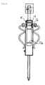
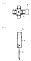
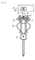
- A denotes a handle
- B denotes a handle fixing tool
- B1 denotes a horizontal hollow
- C denotes a handle axis
- D denotes a clip chuck
- D1 and D2 denote base parts of clip chuck
- D3 and D4 denote top ends of clip chuck
- E denotes a screwdriver
- E1 denotes a socket hole of the screwdriver
- E2 denotes a screwdriver chip
- F denotes a screw
- G denotes a support plate
- H denotes a band
- I denotes a notch portion
- J denotes a screw.
- Fig. 1 is a front view of a screwdriver
- Fig. 2 is a side view thereof
- Fig. 3 is a bottom view thereof
- Fig. 8 is a perspective view thereof.
- a reference symbol A denotes a handle.
- the handle has narrow width so as to be easily put in a palm of a hand, and a length of one side is short and a length of the other side is long.
- the index finger and a middle finger can be brought to a left-front side as there is nothing ahead, and a movable range can be widely used.
- the handle is long on a side of a wrist. Therefore, when a position of the hand is moved to the side of the wrist, the movable range of the hand can be changed.
- a reference symbol B in Figs. 1 to 3 denotes a handle fixing tool for preventing the handle from slipping out of an axis.
- the handle since the handle itself is not fixed, the handle is prevented from slipping out and a part which is lower than the handle is rotatable.
- a horizontal hollow B1 is provided in the handle A, and a hole through which a handle axis C passes from a lower side is further provided in the hollow B1.
- an upper end of the handle axis C is fitted into the through hole and at the same time a circular fixing tool which is larger than the through hole is fitted into the upper end of the handle axis C.
- the fixing tool is fixed to the handle axis C by a screw.
- the handle axis C is coupled to the handle A and is rotatable.
- a reference symbol E in Figs. 1 to 3 denotes a screwdriver main body
- a reference symbol D denotes a clip chuck portion for setting the screwdriver.
- This chuck portion is formed by crosswise putting bottom parts of U-shaped members having two curved parts and coupling the U-shaped members to each other by a band H with utilizing support plates G. Further, these support plates G are fixed to the handle axis C by a screw F.
- this chuck portion has a shape of an impeller formed by putting spring clips crosswise.
- the U-shaped members are metal members having a certain degree of elasticity at top ends thereof and strong rigidity at base parts near bottoms thereof.
- the chuck portion formed by crosswise putting the two U-shaped members can be rotated by suspending fingers of the right hand over impeller blade parts, that is, side parts of the U-shaped members.
- Size of the entire clip chuck (size of the entire side parts of the U-shaped members, circle diameter) is larger than the handle axis C, and it is easy to apply a force. Therefore, suspending rotation can be performed by not using a thumb but only an index finger, a middle finger or the like. Even when the handle is held by the right hand and a part of the impeller is rotated in a palm of a left hand, the screwdriver can be easily and largely rotated.
- the screwdriver is set by inserting the handle axis C into a socket hole E1. Thereby, vertical directions of the handle axis C and the screwdriver correspond to each other, and the axis is prevented from being moved by the force from a horizontal direction.
- Reference symbols D1 and D2 in Fig. 1 are the base parts of the clip chuck. As shown in Fig. 3 , the parts are formed in a square shape to be unevenly but closely adhered to four surfaces of a square of the screwdriver. These robust square parts are to endure the force in a rotational direction imposed on a rotation axis of the screwdriver.
- Reference symbols D3 and D4 in Fig. 1 are top end parts of the clip chuck. Since the clips are spring clips, the force is inwardly imposed on the top end parts shown in Fig. 3 so as to retain and prevent the screwdriver from slipping out.
- the screwdriver E in Fig. 1 can be easily removed as shown in Figs. 4 , 5 , 6 and 7 . According to need, the screwdriver can be set for use or removed for use. According to need, when the screwdriver is changed to a screwdriver in which a top end part E2 is different, for example, provided with a plus shaped chip or the chip itself is changed, a quick exchange and various usage can be realized.
- the screwdriver main body is usable as a normal screwdriver when removed from the chuck portion.
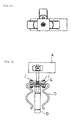
- Fig. 9 is a front view of a screwdriver with a rotation assist of another embodiment of the present invention.
- Fig. 10 is a side view of the screwdriver.
- Fig. 11 is a bottom view of the screwdriver.
- Fig. 12 is a front view of the screwdriver from which a screwdriver main body is removed.
- Fig. 13 is a bottom view of Fig. 12 .
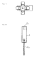
- Fig. 14 is a front view of the screwdriver main body of the screwdriver.
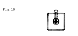
- Fig. 15 is a bottom view of Fig. 14 .
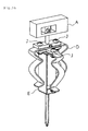
- Fig. 16 is a perspective view of the screwdriver.
- Another embodiment is different from the screwdriver of the above-mentioned embodiment in terms of the following point. That is, in the above-mentioned embodiment, the support plates G are fixed to each other by the band H and also coupled with the clip chuck portion D so as to be fixed to the axis C.
- another embodiment has a different point that the support plates G are fixed to each other by a screw J and also coupled with the clip chuck portion D so as to be fixed to the axis C.
Landscapes
- Engineering & Computer Science (AREA)
- Mechanical Engineering (AREA)
- Details Of Spanners, Wrenches, And Screw Drivers And Accessories (AREA)
Applications Claiming Priority (2)
| Application Number | Priority Date | Filing Date | Title |
|---|---|---|---|
| JP2007196719 | 2007-06-30 | ||
| PCT/JP2008/060818 WO2009004910A1 (ja) | 2007-06-30 | 2008-06-06 | 回転アシスト付ドライバー |
Publications (1)
| Publication Number | Publication Date |
|---|---|
| EP2163346A1 true EP2163346A1 (de) | 2010-03-17 |
Family
ID=40225964
Family Applications (1)
| Application Number | Title | Priority Date | Filing Date |
|---|---|---|---|
| EP08765559A Withdrawn EP2163346A1 (de) | 2007-06-30 | 2008-06-06 | Antrieb mit umkehrhilfe |
Country Status (5)
| Country | Link |
|---|---|
| US (1) | US20110174120A1 (de) |
| EP (1) | EP2163346A1 (de) |
| JP (1) | JP4352436B2 (de) |
| CN (1) | CN101687313B (de) |
| WO (1) | WO2009004910A1 (de) |
Families Citing this family (1)
| Publication number | Priority date | Publication date | Assignee | Title |
|---|---|---|---|---|
| KR101504668B1 (ko) * | 2013-11-29 | 2015-03-20 | 한전케이피에스 주식회사 | 스페이서 클립 설치 장치 |
Family Cites Families (16)
| Publication number | Priority date | Publication date | Assignee | Title |
|---|---|---|---|---|
| US2725086A (en) * | 1952-01-09 | 1955-11-29 | Edward N Keyes | Detachable grip for increasing leverage of tool handles |
| JPS4419120Y1 (de) * | 1966-07-02 | 1969-08-16 | ||
| JPS5037998U (de) * | 1973-08-01 | 1975-04-19 | ||
| US4102375A (en) * | 1977-01-31 | 1978-07-25 | Rossini James L | Variable-length tool holder |
| JPS57131269U (de) * | 1981-02-05 | 1982-08-16 | ||
| JPS5993875U (ja) * | 1982-12-16 | 1984-06-26 | 斎藤 喜定 | ドライバ− |
| JPS6416280U (de) * | 1987-07-17 | 1989-01-26 | ||
| US4825733A (en) * | 1987-09-28 | 1989-05-02 | Chinchar Victor M | Multi-leverage, variable handling twist turn wrench |
| US5592860A (en) * | 1995-12-15 | 1997-01-14 | Woodsum; David A. | Ratchet socket brake and starter tool |
| GB9907463D0 (en) * | 1999-03-31 | 1999-05-26 | Black & Decker Inc | Drill/driver chuck |
| US7093524B2 (en) * | 2002-11-20 | 2006-08-22 | Chih-Ching Hsieh | Screwdriver structure |
| CN2736112Y (zh) * | 2004-07-26 | 2005-10-26 | 王剑 | 拾物器 |
| CN2815621Y (zh) * | 2005-03-15 | 2006-09-13 | 上海环达计算机科技有限公司 | 辅助夹具 |
| JP4859092B2 (ja) | 2005-07-25 | 2012-01-18 | エスケー化研株式会社 | 模様形成方法 |
| US7373860B1 (en) * | 2006-07-19 | 2008-05-20 | Rinner James A | Screwdriver T-handle |
| JP2008168418A (ja) * | 2007-01-13 | 2008-07-24 | Akira Nakamura | ドライバー回転アシスト |
-
2008
- 2008-06-06 EP EP08765559A patent/EP2163346A1/de not_active Withdrawn
- 2008-06-06 CN CN2008800012834A patent/CN101687313B/zh not_active Expired - Fee Related
- 2008-06-06 WO PCT/JP2008/060818 patent/WO2009004910A1/ja not_active Ceased
- 2008-06-06 US US12/439,914 patent/US20110174120A1/en not_active Abandoned
- 2008-06-06 JP JP2009521568A patent/JP4352436B2/ja not_active Expired - Fee Related
Non-Patent Citations (1)
| Title |
|---|
| See references of WO2009004910A1 * |
Also Published As
| Publication number | Publication date |
|---|---|
| JP4352436B2 (ja) | 2009-10-28 |
| US20110174120A1 (en) | 2011-07-21 |
| CN101687313A (zh) | 2010-03-31 |
| JPWO2009004910A1 (ja) | 2010-08-26 |
| WO2009004910A1 (ja) | 2009-01-08 |
| CN101687313B (zh) | 2011-08-17 |
Similar Documents
| Publication | Publication Date | Title |
|---|---|---|
| EP1967119A3 (de) | Reinigungswerkzeug | |
| US5606772A (en) | Ergonomic handle grip for tools | |
| EP2716413B1 (de) | Sparrenhacke für Befestigungswerkzeug | |
| CN100478106C (zh) | 用于手持动力工具的带夹 | |
| US7757590B2 (en) | Fastener holding device | |
| RU2007135993A (ru) | Ручной инструмент (варианты) и ручка для ручного инструмента | |
| KR200461856Y1 (ko) | 의료용 수동 드라이버 | |
| CN208409710U (zh) | 多功能棘轮阀门扳手 | |
| EP2163346A1 (de) | Antrieb mit umkehrhilfe | |
| CN204277907U (zh) | 安装钳 | |
| CN207333414U (zh) | 手拧螺丝钉 | |
| WO2004016393A1 (en) | Chamfering tool | |
| CN203998338U (zh) | 可同时收纳及使用多种胶带的手持式胶带切割器结构 | |
| CN106475924A (zh) | 一种新型五金加工用工具钳 | |
| CN203317249U (zh) | C型扣环钳结构 | |
| WO2020150359A3 (en) | Gripping hand tools | |
| CN209503890U (zh) | 一种tpe钳子柄 | |
| CN217915046U (zh) | 一种阀门手轮用扳手 | |
| JP2010094798A (ja) | ギヤ(歯車)付回転アシストドライバ− | |
| TWM412041U (en) | Sleeve-type hand tool | |
| US9789594B2 (en) | Oil filter wrench | |
| CN203509975U (zh) | 人体工学枪形钳 | |
| CN105879948B (zh) | 一种便携试管夹 | |
| CN2157857Y (zh) | 鹰爪旋具 | |
| JP2008168418A (ja) | ドライバー回転アシスト |
Legal Events
| Date | Code | Title | Description |
|---|---|---|---|
| PUAI | Public reference made under article 153(3) epc to a published international application that has entered the european phase |
Free format text: ORIGINAL CODE: 0009012 |
|
| 17P | Request for examination filed |
Effective date: 20090730 |
|
| AK | Designated contracting states |
Kind code of ref document: A1 Designated state(s): AT BE BG CH CY CZ DE DK EE ES FI FR GB GR HR HU IE IS IT LI LT LU LV MC MT NL NO PL PT RO SE SI SK TR |
|
| AX | Request for extension of the european patent |
Extension state: AL BA MK RS |
|
| DAX | Request for extension of the european patent (deleted) | ||
| STAA | Information on the status of an ep patent application or granted ep patent |
Free format text: STATUS: THE APPLICATION HAS BEEN WITHDRAWN |
|
| 18W | Application withdrawn |
Effective date: 20110524 |