EP2163732A2 - Positioniermechanismus eines Turbinenlagers - Google Patents
Positioniermechanismus eines Turbinenlagers Download PDFInfo
- Publication number
- EP2163732A2 EP2163732A2 EP09169307A EP09169307A EP2163732A2 EP 2163732 A2 EP2163732 A2 EP 2163732A2 EP 09169307 A EP09169307 A EP 09169307A EP 09169307 A EP09169307 A EP 09169307A EP 2163732 A2 EP2163732 A2 EP 2163732A2
- Authority
- EP
- European Patent Office
- Prior art keywords
- socket
- pin
- ball
- conical
- axis
- Prior art date
- Legal status (The legal status is an assumption and is not a legal conclusion. Google has not performed a legal analysis and makes no representation as to the accuracy of the status listed.)
- Withdrawn
Links
- 230000007246 mechanism Effects 0.000 title claims abstract description 37
- 230000005540 biological transmission Effects 0.000 claims abstract description 3
- 238000000034 method Methods 0.000 claims description 23
- 238000007667 floating Methods 0.000 claims description 3
- 238000002485 combustion reaction Methods 0.000 description 7
- 230000004323 axial length Effects 0.000 description 6
- 238000003780 insertion Methods 0.000 description 6
- 230000037431 insertion Effects 0.000 description 6
- 239000000314 lubricant Substances 0.000 description 6
- 238000010586 diagram Methods 0.000 description 5
- 239000000463 material Substances 0.000 description 5
- 239000012530 fluid Substances 0.000 description 4
- 230000033001 locomotion Effects 0.000 description 4
- 238000001816 cooling Methods 0.000 description 2
- 230000003467 diminishing effect Effects 0.000 description 2
- 238000005516 engineering process Methods 0.000 description 2
- 238000005461 lubrication Methods 0.000 description 2
- 230000001419 dependent effect Effects 0.000 description 1
- 239000000284 extract Substances 0.000 description 1
- 238000003754 machining Methods 0.000 description 1
- 238000012423 maintenance Methods 0.000 description 1
- 238000004519 manufacturing process Methods 0.000 description 1
- 238000007789 sealing Methods 0.000 description 1
- 125000006850 spacer group Chemical group 0.000 description 1
- 238000007514 turning Methods 0.000 description 1
- 238000003466 welding Methods 0.000 description 1
Images




Classifications
-
- F—MECHANICAL ENGINEERING; LIGHTING; HEATING; WEAPONS; BLASTING
- F01—MACHINES OR ENGINES IN GENERAL; ENGINE PLANTS IN GENERAL; STEAM ENGINES
- F01D—NON-POSITIVE DISPLACEMENT MACHINES OR ENGINES, e.g. STEAM TURBINES
- F01D25/00—Component parts, details, or accessories, not provided for in, or of interest apart from, other groups
- F01D25/16—Arrangement of bearings; Supporting or mounting bearings in casings
- F01D25/166—Sliding contact bearing
-
- F—MECHANICAL ENGINEERING; LIGHTING; HEATING; WEAPONS; BLASTING
- F16—ENGINEERING ELEMENTS AND UNITS; GENERAL MEASURES FOR PRODUCING AND MAINTAINING EFFECTIVE FUNCTIONING OF MACHINES OR INSTALLATIONS; THERMAL INSULATION IN GENERAL
- F16C—SHAFTS; FLEXIBLE SHAFTS; ELEMENTS OR CRANKSHAFT MECHANISMS; ROTARY BODIES OTHER THAN GEARING ELEMENTS; BEARINGS
- F16C17/00—Sliding-contact bearings for exclusively rotary movement
- F16C17/10—Sliding-contact bearings for exclusively rotary movement for both radial and axial load
-
- F—MECHANICAL ENGINEERING; LIGHTING; HEATING; WEAPONS; BLASTING
- F16—ENGINEERING ELEMENTS AND UNITS; GENERAL MEASURES FOR PRODUCING AND MAINTAINING EFFECTIVE FUNCTIONING OF MACHINES OR INSTALLATIONS; THERMAL INSULATION IN GENERAL
- F16C—SHAFTS; FLEXIBLE SHAFTS; ELEMENTS OR CRANKSHAFT MECHANISMS; ROTARY BODIES OTHER THAN GEARING ELEMENTS; BEARINGS
- F16C35/00—Rigid support of bearing units; Housings, e.g. caps, covers
- F16C35/02—Rigid support of bearing units; Housings, e.g. caps, covers in the case of sliding-contact bearings
-
- F—MECHANICAL ENGINEERING; LIGHTING; HEATING; WEAPONS; BLASTING
- F05—INDEXING SCHEMES RELATING TO ENGINES OR PUMPS IN VARIOUS SUBCLASSES OF CLASSES F01-F04
- F05D—INDEXING SCHEME FOR ASPECTS RELATING TO NON-POSITIVE-DISPLACEMENT MACHINES OR ENGINES, GAS-TURBINES OR JET-PROPULSION PLANTS
- F05D2220/00—Application
- F05D2220/40—Application in turbochargers
-
- F—MECHANICAL ENGINEERING; LIGHTING; HEATING; WEAPONS; BLASTING
- F05—INDEXING SCHEMES RELATING TO ENGINES OR PUMPS IN VARIOUS SUBCLASSES OF CLASSES F01-F04
- F05D—INDEXING SCHEME FOR ASPECTS RELATING TO NON-POSITIVE-DISPLACEMENT MACHINES OR ENGINES, GAS-TURBINES OR JET-PROPULSION PLANTS
- F05D2230/00—Manufacture
- F05D2230/60—Assembly methods
- F05D2230/64—Assembly methods using positioning or alignment devices for aligning or centring, e.g. pins
-
- F—MECHANICAL ENGINEERING; LIGHTING; HEATING; WEAPONS; BLASTING
- F05—INDEXING SCHEMES RELATING TO ENGINES OR PUMPS IN VARIOUS SUBCLASSES OF CLASSES F01-F04
- F05D—INDEXING SCHEME FOR ASPECTS RELATING TO NON-POSITIVE-DISPLACEMENT MACHINES OR ENGINES, GAS-TURBINES OR JET-PROPULSION PLANTS
- F05D2250/00—Geometry
- F05D2250/20—Three-dimensional
- F05D2250/23—Three-dimensional prismatic
- F05D2250/232—Three-dimensional prismatic conical
-
- F—MECHANICAL ENGINEERING; LIGHTING; HEATING; WEAPONS; BLASTING
- F05—INDEXING SCHEMES RELATING TO ENGINES OR PUMPS IN VARIOUS SUBCLASSES OF CLASSES F01-F04
- F05D—INDEXING SCHEME FOR ASPECTS RELATING TO NON-POSITIVE-DISPLACEMENT MACHINES OR ENGINES, GAS-TURBINES OR JET-PROPULSION PLANTS
- F05D2250/00—Geometry
- F05D2250/20—Three-dimensional
- F05D2250/24—Three-dimensional ellipsoidal
- F05D2250/241—Three-dimensional ellipsoidal spherical
-
- F—MECHANICAL ENGINEERING; LIGHTING; HEATING; WEAPONS; BLASTING
- F16—ENGINEERING ELEMENTS AND UNITS; GENERAL MEASURES FOR PRODUCING AND MAINTAINING EFFECTIVE FUNCTIONING OF MACHINES OR INSTALLATIONS; THERMAL INSULATION IN GENERAL
- F16C—SHAFTS; FLEXIBLE SHAFTS; ELEMENTS OR CRANKSHAFT MECHANISMS; ROTARY BODIES OTHER THAN GEARING ELEMENTS; BEARINGS
- F16C2226/00—Joining parts; Fastening; Assembling or mounting parts
- F16C2226/50—Positive connections
-
- F—MECHANICAL ENGINEERING; LIGHTING; HEATING; WEAPONS; BLASTING
- F16—ENGINEERING ELEMENTS AND UNITS; GENERAL MEASURES FOR PRODUCING AND MAINTAINING EFFECTIVE FUNCTIONING OF MACHINES OR INSTALLATIONS; THERMAL INSULATION IN GENERAL
- F16C—SHAFTS; FLEXIBLE SHAFTS; ELEMENTS OR CRANKSHAFT MECHANISMS; ROTARY BODIES OTHER THAN GEARING ELEMENTS; BEARINGS
- F16C2360/00—Engines or pumps
- F16C2360/23—Gas turbine engines
- F16C2360/24—Turbochargers
-
- Y—GENERAL TAGGING OF NEW TECHNOLOGICAL DEVELOPMENTS; GENERAL TAGGING OF CROSS-SECTIONAL TECHNOLOGIES SPANNING OVER SEVERAL SECTIONS OF THE IPC; TECHNICAL SUBJECTS COVERED BY FORMER USPC CROSS-REFERENCE ART COLLECTIONS [XRACs] AND DIGESTS
- Y10—TECHNICAL SUBJECTS COVERED BY FORMER USPC
- Y10T—TECHNICAL SUBJECTS COVERED BY FORMER US CLASSIFICATION
- Y10T29/00—Metal working
- Y10T29/49—Method of mechanical manufacture
- Y10T29/49229—Prime mover or fluid pump making
- Y10T29/49236—Fluid pump or compressor making
- Y10T29/49245—Vane type or other rotary, e.g., fan
Definitions
- Subject matter disclosed herein relates generally to bearing systems for turbomachinery such as turbochargers for internal combustion engines.
- Turbomachines rely on turbines to convert fluid energy to mechanical energy.
- a turbine is connected to a shaft supported by one or more bearings where the shaft rotates along with the turbine as the turbine extracts energy from a fluid stream.
- a shaft may rotate at over 100,000 rpm.
- Such rotational speeds place significant demands on bearing systems, especially as to lubrication and cooling.
- a fluid such as a natural or synthetic oil is used to lubricate as well as cool a bearing system. To ensure adequate fluid flow for lubrication and cooling, clearances between components in a bearing system should be maintained within strict limits.
- clearances in a bearing system impact clearances in a bearing system. These factors include machining accuracy, material properties, assembly techniques and the like. If a component cannot be machined reproducibly and accurately, then clearances may deviate from component to component and collectively from assembly to assembly. Further, if material properties allow for unacceptable wear, which may generate debris, clearances can change over time. Yet further, if an assembly technique introduces variation, then clearances from assembly to assembly may be unacceptable.
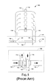
- Fig. 1 is a simplified approximate diagram illustrating a prior art turbocharger system for an internal combustion engine.
- Fig. 2 is cross-sectional view of an assembly with an exemplary bearing system suitable for use with the internal combustion engine of Fig. 1 .
- Fig. 3 is an enlarged cross-sectional view of a portion of the assembly of Fig. 2 .
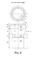
- Fig. 4 is a side view and top view of an exemplary conical pin as shown in Figs. 2 and 3 .
- Fig. 5 is a cross-sectional view of an exemplary opening of the center housing of the assembly of Figs. 2 and 3 .
- Fig. 6 is a block diagram of an exemplary method for assembling a bearing system.
- program modules include instructions, routines, programs, objects, components, data structures, etc.
- One or more computer-readable media may be used to store such information.
- One or more machines may, at least in part, be programmed or otherwise instructed to perform part or all of various methods described herein.
- various algorithmic acts are summarized in individual "blocks". Such blocks describe specific actions or decisions that are made or carried out as a process proceeds.
- a controller or equivalent
- the flow charts presented herein provide a basis for a "control program” or software/firmware that may be used by such a controller (or equivalent) to control a device and/or a system.
- various processes may be implemented as machine-readable instructions storable in memory that, when executed by a processor, perform various acts illustrated as blocks.
- various diagrams include individual “blocks” that are optionally structural elements of a device and/or a system.
- a "controller block” optionally includes a controller as a structural element.
- a prior art power system 100 includes an internal combustion engine 110 and a turbocharger 120.
- the internal combustion engine 110 includes an engine block 118 housing one or more combustion chambers that operatively drive a shaft 112.
- An intake port 114 provides a flow path for compressed intake air to the engine block while an exhaust port 116 provides a flow path for exhaust from the engine block 118.
- the turbocharger 120 acts to extract energy from the exhaust and to provide energy to the intake air.
- the turbocharger 120 includes an air inlet 130, a shaft 122, a compressor stage 124, a turbine stage 126 and an exhaust outlet 134.
- the turbine stage 126 optionally includes a variable geometry unit and a variable geometry controller.
- the variable geometry unit and variable geometry controller optionally include features such as those associated with commercially available variable geometry turbochargers (VGTs).
- VGTs include, for example, the GARRETT® VNT TM and AVNT TM turbochargers, which use multiple adjustable vanes to control the flow of exhaust across a turbine.
- An exemplary turbocharger may employ wastegate technology as an alternative or in addition to variable geometry technology.
- the compressor stage 124 optionally includes features to control the flow of intake air (e.g., variable geometry compressor).
- the turbine stage 126 includes a turbine wheel (see, e.g., the wheel 226 of Fig. 2 ) housed in a turbine housing and the compressor stage 124 includes a compressor wheel (see, e.g., wheel 224 of Fig. 2 ) housed in a compressor housing where the turbine housing and compressor housing connect directly or indirectly to a center housing 121 (see also housing 210 of Fig. 2 ).
- the center housing 121 typically houses one or more bearings that rotatably support the shaft 122, which is optionally a multi-component shaft.
- Fig. 2 shows an exemplary assembly 200 that includes a housing 210 having a compressor end 202 and a turbine end 204.
- the housing 210 is a center housing of a turbocharger assembly such as the housing 121 of Fig. 1 .
- the housing 210 houses an exemplary bearing locating mechanism 300 for a bearing 220.
- the mechanism 300 relies on a locating mechanism socket 302 configured to receives a pin 320 and a ball 330.
- the turbine wheel 226 and the shaft 222 may be a single component, for example, manufactured by welding a turbine to a shaft. Whether a single component or multi-component configuration is used, one or more sealing mechanisms exist to reduce leakage of lubricant from the bearing space to the turbine wheel space.
- the turbine wheel 226 includes a pair of axially spaced grooves where each groove seats a seal ring 229.
- the compressor wheel 224 is spaced axially from the bearing 220 by a spacer 225, which includes a groove that seats a seal ring 227. Such a seal mechanism reduces leakage of lubricant toward the compressor wheel 201.
- the housing 210 includes a bearing bore 212 for the bearing 220.
- the bearing 220 includes an aperture 221 for receiving a locating pin 320 that extends into the bearing bore 212.
- the bearing 220 can be constrained from rotating and translating in the bearing bore 212 of the center housing 210.
- the bearing 220 is semi-floating and has, to some extent, freedom of movement from end to end and within a clearance between the bearing 220 and the bore 212.
- the locating mechanism 300 includes features that may, at first, appear to limit such movement, attention to desired clearances and locating mechanism(s) specifics can provide for some end to end movement while maintaining some clearance for radial lubricant flow between the bearing 220 and the housing 210 at the compressor end 202 of the assembly or at the turbine end 204 of the assembly. In Fig. 2 , some clearance may exist between the locating pin 230 and the bearing 220.
- the housing 210 includes an opening 206 to the locating mechanism socket 302, which is configured to receive the locating pin 320 and a ball 330.
- the locating pin 320 is received by the opening 206 of the housing 210, set in the socket 302 and inserted into the aperture 221 of the bearing 220.
- the ball 330 is then received by the opening 206, set in the socket 302 and an axial load is applied to the ball 330 to position and secure the locating pin 320.
- the ball 330 is positioned in the socket 302 such that the load applied to the ball 330 is transferred to the locating pin 320 substantially along its axis. Further, the ball 330 may create a seal about a circumference to thereby prevent debris from entering the opening 206. Such debris could potentially affect the locating pin 320 (e.g., its material, its fit and/or its alignment).
- a locating mechanism may be from a side or bottom.
- an exemplary assembly may optionally include two or more locating mechanisms (e.g., an exemplary mechanism and another type of locating mechanism, two exemplary mechanisms, etc.).
- Fig. 3 shows an enlarged cross-sectional view of the locating mechanism 300 of Fig. 2 .
- the locating mechanism 300 relies on the socket 302 disposed in the housing 210, the locating pin 320 and the ball 330 to maintain proper alignment of the locating pin 320 with respect to the housing 210 and the bearing 220.
- the locating pin 320 includes a conical wall portion 323 that aligns with a corresponding conical surface 314 of the socket 302 of the housing 210.
- the conical wall portion 323 and the conical surface 314 may be relatively smooth to provide increased contact area.
- the wall portion 323 and/or the conical surface 314 may be alternatively or additionally treated in a manner to increase friction (i.e., the force resisting relative motion of the conical wall portion 323 along the conical surface 314).
- the conical wall portion 323 is defined with respect to an axis of the pin 320 and the conical surface 314 is defined with respect to an axis of the socket 302.
- these axes are aligned such that conical wall portion 323 of the pin 320 and the conical surface 314 of the socket 302 contact with diminishing diameter along a direction from the opening 206 to the bore 212 of the housing 210 (e.g., from the head to the bottom of the pin 320).
- the pin 320 may include one or more features that allow for twisting or pulling the pin 320 from the socket 302 of the housing 210.
- the pin 320 may include a threaded well along its axis or at an off-axis position (e.g., to not interfere with axial force applied by the ball 330).
- An exemplary bearing assembly may allow for access to the bottom of the pin 320 where force may be applied to push the pin (e.g., through an opening of the bearing 220, which may be accessed via an opening in a housing).
- the ball 330 (e.g., sphere) is seated along a cylindrical surface 310 of the socket 302.
- the diameter of the ball 330 and the diameter of the cylindrical surface 310 allow the ball 330 to be inserted and pressure fit (e.g., mechanical interference) to form a seal 331 between a circumference of the ball 330 and the cylindrical surface 310.
- the seal 331 can prevent debris from reaching the pin 320.
- the seal 331 can help prevent leakage of lubricant from the bore 212 of the housing 210; noting that the conical wall portion 323 and the conical surface 314 may form a seal that prevents leakage of lubricant from the bore 212 of the housing 210.
- the pin 320 and/or the ball 330 may seal the socket 302 (e.g., to form a seal or seals between the bore 212 and the opening 206 of the housing).
- the ball 330 and the cylindrical surface 310 may be configured to retain the ball 330 in the socket 302 or they may be configured to allow for removal of the ball 330 (e.g., after seating the pin 320). In either instance, the ball 330 may include one or more features that allow for removal of the ball 330 from the socket 302 (e.g., a threaded well or other feature).
- the ball 330 allows for transferring force to the pin 320.
- the cylindrical surface 310 and conical surface 314 of the socket 302 are defined along a common axis where insertion of the ball 330 into the socket 302 allows the ball 330 to form a contact 333 with the pin 320 along its axis. As force is applied to the ball 330, to seat the pin 320, these axes become aligned with greater accuracy.
- the pin 320 includes a pin portion 325, which is substantially cylindrical and that extends into the bore 212 of the housing 210 and into the aperture 221 of the bearing 220 to thereby locate the bearing 220 in the bore 212.
- a mechanism can improve the perpendicularity between the pin 320 and the bearing 220.
- Such a mechanism can also improve hosing cast feasibility, improve aspects of assembly and reduce costs. Improved perpendicularity of the pin 320 to the bearing 220 can reduce wear (e.g., the mechanism helps to maintain proper surface contact between components).
- the bearing 220 is often subject to extreme conditions, including high temperature and force.
- the exemplary locating mechanism 330 improves the relationship between the pin 320 and the bearing 220 and thus allows the bearing 220 to operate with more certainty as to position, which, in turn, can help maintain clearances, maintain lubricant flow and, in general, reduce wear.
- Fig. 4 shows a side view and a top view of the conical pin 320 of Figs. 2 and 3 .
- the pin 320 is described with respect to various portions 321, 322, 323, 324 and 325. These portions are further described with respect to radii, surfaces and axial lengths or "heights”.
- a beveled portion 321 of the pin 320 has a surface s 0 , an axial length ⁇ h 0 , an upper radius r 0 and a lower radius r 1 .
- a cylindrical portion 322 of the pin 320 has a surface S 1 , an axial length ⁇ h 1 and a radius r 1 .
- the conical wall portion 323 of the pin 320 has a surface S 2 , an axial length ⁇ h 2 , an upper radius r 1 and a lower radius r 2 .
- a neck portion 324 of the pin 320 is substantially cylindrical and has a surface S 3 , an axial length ⁇ h 3 and a radius r 3 .
- the pin portion 325 of the pin 320 is substantially cylindrical and has a surface S 4 , an axial length ⁇ h 4 , an upper radius r 4 and a lower radius r 5 (e.g., which may be smaller that r 4 due to a beveled edge).
- the conical wall portion 323 has a diminishing radius along the axis of the pin 320.
- the conical surface 314 of the socket 302 may have an angle of about 30° as well.
- Fig. 5 shows a cross-sectional view of the locating mechanism socket 302.
- the opening 206 of the housing 210 may be considered an opening of the socket 302.
- the socket 302 includes the cylindrical surface 310, which has an axial height of ⁇ h b and a radius of r b (where "b" is an abbreviation of "ball”); a step to a cylindrical surface 312, which has an axial height of ⁇ h h and a radius of r h (where "h” is an abbreviation of "head” as in pin head); a step to the conical surface 314, which has an axial height of ⁇ h c and a height dependent radius of r c (h); and the cylindrical surface 316, which has an axial height of ⁇ h p and a radius of rp (where "p” is an abbreviation of "pin” as in pin portion).
- an exemplary locating mechanism for locating a turbine bearing in a bore of a housing includes a conical pin having a pin axis and including a conical wall portion and a pin portion to locate a turbine bearing; a ball; and a socket disposed in a housing and extending between an opening of the housing and a bore of the housing, the socket having a socket axis where the socket includes a cylindrical surface and a conical surface, where disposition of the conical pin in the socket seats the conical pin along the socket axis and against the conical surface, where disposition of the ball in the socket seats the ball along the socket axis and against the cylindrical surface, and where alignment of the ball with respect to the conical pin allows for transmission of force from the ball to the conical pin along the pin axis.
- Such a mechanism may further include the turbine bearing where the turbine bearing has an aperture configured to receive the pin portion of the conical pin.
- a ball may form a seal with a cylindrical surface of a socket.
- an interference may exist between the ball and the cylindrical surface of the socket defined by a small dimension of about 0.1 mm or less (e.g., approximately 0.05 mm).
- a conical wall portion of a conical pin may have an angle in a range of about 10° to about 50° (e.g., approximately 30°) with respect to the pin axis. In general, the angle allows for adequate transfer of force and seating; noting that other angles may be possible.
- a socket of a housing can include a corresponding angle.
- an exemplary assembly for a turbocharger includes a bearing having a longitudinal axis, configured to support a turbocharger shaft along the longitudinal axis and including an aperture having an aperture axis perpendicular to the longitudinal axis; a housing that includes a bore to receive the bearing, and a socket, where the socket extends between an opening of the housing and the bore of the housing, the socket having a socket axis perpendicular to the longitudinal axis of the bearing and where the socket includes a cylindrical surface and a conical surface; a ball disposed in the socket along the socket axis and seated against the cylindrical surface of the socket; and a conical pin, having a pin axis, disposed in the socket along the socket axis and seated against the conical surface of the socket where the conical pin includes a pin portion received by the aperture of the bearing; where the ball contacts the conical pin at the pin axis to thereby allow for transfer of force from the ball to the conical pin.
- the conical pin having a pin
- Fig. 6 shows a block diagram of an exemplary method 600.
- the method 600 includes an insertion step 604 for inserting a bearing into a bore of a housing.
- the insertion step 604 is followed by another insertion step 608 for inserting a conical pin into an opening of the housing. While it may be possible to perform the step 608 prior to the step 604, in general, step 608 follows step 604.
- the method 600 includes yet another insertion step 612 for inserting a ball into the opening of the housing.
- the insertion step 612 is followed by an application step 616 for applying a load to the ball.
- the application step 616 acts to complete the method 600, as indicated by a completion step 620 where the pin is now positioned to locate the bearing and whereby the opening of the housing is now sealed.
- an exemplary method includes inserting a bearing into a bore of a housing where the bearing includes a longitudinal axis and an aperture, the aperture having an aperture axis perpendicular to the longitudinal axis; inserting a conical pin into a socket of the housing where the socket extends to the bore of the housing and where the conical pin includes a pin axis and a pin portion for receipt by the aperture of the bearing; inserting a ball into the socket of the housing; and applying a load to the ball to thereby seat the conical pin in the socket and locate the bearing in the bore.
- Such a method may include applying a load to the ball to form a seal between the ball and the socket.
- an interference may exist between the socket and the ball to allow the socket to forcibly retain the ball.
- the ball retains the conical pin in the socket.
Landscapes
- Engineering & Computer Science (AREA)
- General Engineering & Computer Science (AREA)
- Mechanical Engineering (AREA)
- Supercharger (AREA)
Applications Claiming Priority (1)
| Application Number | Priority Date | Filing Date | Title |
|---|---|---|---|
| US12/211,761 US8186947B2 (en) | 2008-09-16 | 2008-09-16 | Conical pin to maintain bearing system |
Publications (1)
| Publication Number | Publication Date |
|---|---|
| EP2163732A2 true EP2163732A2 (de) | 2010-03-17 |
Family
ID=41161318
Family Applications (1)
| Application Number | Title | Priority Date | Filing Date |
|---|---|---|---|
| EP09169307A Withdrawn EP2163732A2 (de) | 2008-09-16 | 2009-09-02 | Positioniermechanismus eines Turbinenlagers |
Country Status (3)
| Country | Link |
|---|---|
| US (1) | US8186947B2 (de) |
| EP (1) | EP2163732A2 (de) |
| CN (1) | CN101676522B (de) |
Cited By (1)
| Publication number | Priority date | Publication date | Assignee | Title |
|---|---|---|---|---|
| EP3284964A1 (de) * | 2016-08-16 | 2018-02-21 | Bosch Mahle Turbo Systems GmbH & Co. KG | Lagereinrichtung eines abgasturboladers |
Families Citing this family (8)
| Publication number | Priority date | Publication date | Assignee | Title |
|---|---|---|---|---|
| CN102741522A (zh) * | 2010-02-19 | 2012-10-17 | 博格华纳公司 | 涡轮机叶轮以及用于生产其的方法 |
| EP2392784A1 (de) * | 2010-06-04 | 2011-12-07 | Siemens Aktiengesellschaft | Dampfturbineneinheit und Verfahren zur Montage einer Dampfturbine |
| US8449199B2 (en) * | 2010-10-27 | 2013-05-28 | Precision Turbo & Engine Rebuilders, Inc. | Bearing retention assembly for and method of assembling turbochargers |
| DE112015004493T5 (de) * | 2014-09-30 | 2017-06-29 | Ihi Corporation | Lagerstruktur und turbolader |
| DE102017218053B4 (de) | 2017-10-10 | 2019-06-19 | Continental Automotive Gmbh | Turboladereinrichtung und Verfahren zu deren Montage |
| US11486268B2 (en) * | 2018-01-15 | 2022-11-01 | Garrett Transportation I Inc. | Turbocharger assembly |
| JP6939910B2 (ja) * | 2018-01-26 | 2021-09-22 | 株式会社Ihi | 軸受構造 |
| US11353040B2 (en) * | 2020-02-29 | 2022-06-07 | Garrett Transportation I Inc. | Turbocharger assembly |
Family Cites Families (10)
| Publication number | Priority date | Publication date | Assignee | Title |
|---|---|---|---|---|
| US3811741A (en) * | 1972-12-26 | 1974-05-21 | Garrett Corp | Bearing |
| US4240678A (en) * | 1979-02-22 | 1980-12-23 | Wallace Murray Corporation | Non-rotating fluid damped combination thrust and journal bearing |
| US4798523A (en) * | 1986-12-19 | 1989-01-17 | Allied-Signal Inc. | Turbocharger bearing and lubrication system |
| JPH0540273Y2 (de) * | 1988-04-26 | 1993-10-13 | ||
| US5145334A (en) * | 1989-12-12 | 1992-09-08 | Allied-Signal Inc. | Turbocharger bearing retention and lubrication system |
| JP3711604B2 (ja) * | 1995-12-26 | 2005-11-02 | 石川島播磨重工業株式会社 | ターボチャージャのハウジング構造 |
| US5993173A (en) | 1996-03-06 | 1999-11-30 | Ishikawajima-Harima Heavy Industries Co., Ltd. | Turbocharger |
| US7214037B2 (en) * | 2004-06-28 | 2007-05-08 | Honeywell International, Inc. | Retention of ball bearing cartridge for turbomachinery |
| JP2006266244A (ja) * | 2005-03-25 | 2006-10-05 | Toyota Motor Corp | ターボチャージャの軸受装置 |
| CN100441833C (zh) * | 2005-09-01 | 2008-12-10 | 黄若 | 混合陶瓷球轴承涡轮增压器 |
-
2008
- 2008-09-16 US US12/211,761 patent/US8186947B2/en not_active Expired - Fee Related
-
2009
- 2009-09-02 EP EP09169307A patent/EP2163732A2/de not_active Withdrawn
- 2009-09-15 CN CN200910173513.1A patent/CN101676522B/zh not_active Expired - Fee Related
Cited By (1)
| Publication number | Priority date | Publication date | Assignee | Title |
|---|---|---|---|---|
| EP3284964A1 (de) * | 2016-08-16 | 2018-02-21 | Bosch Mahle Turbo Systems GmbH & Co. KG | Lagereinrichtung eines abgasturboladers |
Also Published As
| Publication number | Publication date |
|---|---|
| US8186947B2 (en) | 2012-05-29 |
| US20100068053A1 (en) | 2010-03-18 |
| CN101676522A (zh) | 2010-03-24 |
| CN101676522B (zh) | 2014-07-09 |
Similar Documents
| Publication | Publication Date | Title |
|---|---|---|
| US8186947B2 (en) | Conical pin to maintain bearing system | |
| US9963998B2 (en) | Assembly with bearings and spacer | |
| EP2573362B1 (de) | Turbolader mit einer Hülse | |
| US8858173B2 (en) | Bearing assembly with damping features | |
| CN101864998B (zh) | 轴承和保持机构 | |
| US9695708B2 (en) | Turbocharger spring assembly | |
| KR102142331B1 (ko) | 터빈 웨이스트게이트 | |
| US9046036B2 (en) | Bearing assembly | |
| EP1972759A2 (de) | Halbtreibendes Lager mit abgestuftem Außendurchmesser | |
| EP3081769B1 (de) | Lageranordnung für turbolader | |
| CN103670540B (zh) | 外座圈定位垫圈 |
Legal Events
| Date | Code | Title | Description |
|---|---|---|---|
| PUAI | Public reference made under article 153(3) epc to a published international application that has entered the european phase |
Free format text: ORIGINAL CODE: 0009012 |
|
| 17P | Request for examination filed |
Effective date: 20090902 |
|
| AK | Designated contracting states |
Kind code of ref document: A2 Designated state(s): AT BE BG CH CY CZ DE DK EE ES FI FR GB GR HR HU IE IS IT LI LT LU LV MC MK MT NL NO PL PT RO SE SI SK SM TR |
|
| STAA | Information on the status of an ep patent application or granted ep patent |
Free format text: STATUS: THE APPLICATION HAS BEEN WITHDRAWN |
|
| 18W | Application withdrawn |
Effective date: 20150911 |