EP2164082A2 - Antennenmodul - Google Patents
Antennenmodul Download PDFInfo
- Publication number
- EP2164082A2 EP2164082A2 EP09168599A EP09168599A EP2164082A2 EP 2164082 A2 EP2164082 A2 EP 2164082A2 EP 09168599 A EP09168599 A EP 09168599A EP 09168599 A EP09168599 A EP 09168599A EP 2164082 A2 EP2164082 A2 EP 2164082A2
- Authority
- EP
- European Patent Office
- Prior art keywords
- casing
- actuating member
- antenna module
- disposed
- key
- Prior art date
- Legal status (The legal status is an assumption and is not a legal conclusion. Google has not performed a legal analysis and makes no representation as to the accuracy of the status listed.)
- Granted
Links
Images



Classifications
-
- H—ELECTRICITY
- H01—ELECTRIC ELEMENTS
- H01H—ELECTRIC SWITCHES; RELAYS; SELECTORS; EMERGENCY PROTECTIVE DEVICES
- H01H3/00—Mechanisms for operating contacts
- H01H3/32—Driving mechanisms, i.e. for transmitting driving force to the contacts
- H01H3/46—Driving mechanisms, i.e. for transmitting driving force to the contacts using rod or lever linkage, e.g. toggle
-
- H—ELECTRICITY
- H01—ELECTRIC ELEMENTS
- H01H—ELECTRIC SWITCHES; RELAYS; SELECTORS; EMERGENCY PROTECTIVE DEVICES
- H01H13/00—Switches having rectilinearly-movable operating part or parts adapted for pushing or pulling in one direction only, e.g. push-button switch
- H01H13/02—Details
- H01H13/023—Light-emitting indicators
-
- H—ELECTRICITY
- H01—ELECTRIC ELEMENTS
- H01H—ELECTRIC SWITCHES; RELAYS; SELECTORS; EMERGENCY PROTECTIVE DEVICES
- H01H3/00—Mechanisms for operating contacts
- H01H3/32—Driving mechanisms, i.e. for transmitting driving force to the contacts
- H01H3/38—Driving mechanisms, i.e. for transmitting driving force to the contacts using spring or other flexible shaft coupling
-
- H—ELECTRICITY
- H04—ELECTRIC COMMUNICATION TECHNIQUE
- H04B—TRANSMISSION
- H04B1/00—Details of transmission systems, not covered by a single one of groups H04B3/00 - H04B13/00; Details of transmission systems not characterised by the medium used for transmission
- H04B1/02—Transmitters
- H04B1/03—Constructional details, e.g. casings, housings
- H04B1/034—Portable transmitters
-
- H—ELECTRICITY
- H01—ELECTRIC ELEMENTS
- H01H—ELECTRIC SWITCHES; RELAYS; SELECTORS; EMERGENCY PROTECTIVE DEVICES
- H01H2219/00—Legends
- H01H2219/036—Light emitting elements
- H01H2219/05—Key offset in relation to switch site
-
- H—ELECTRICITY
- H01—ELECTRIC ELEMENTS
- H01H—ELECTRIC SWITCHES; RELAYS; SELECTORS; EMERGENCY PROTECTIVE DEVICES
- H01H2221/00—Actuators
- H01H2221/024—Transmission element
-
- H—ELECTRICITY
- H01—ELECTRIC ELEMENTS
- H01H—ELECTRIC SWITCHES; RELAYS; SELECTORS; EMERGENCY PROTECTIVE DEVICES
- H01H2237/00—Mechanism between key and laykey
- H01H2237/002—Bell crank
-
- H—ELECTRICITY
- H01—ELECTRIC ELEMENTS
- H01R—ELECTRICALLY-CONDUCTIVE CONNECTIONS; STRUCTURAL ASSOCIATIONS OF A PLURALITY OF MUTUALLY-INSULATED ELECTRICAL CONNECTING ELEMENTS; COUPLING DEVICES; CURRENT COLLECTORS
- H01R2201/00—Connectors or connections adapted for particular applications
- H01R2201/02—Connectors or connections adapted for particular applications for antennas
Definitions
- the invention relates in general to an antenna module, and more particularly to an antenna module having a key.
- USB universal serial bus
- the antenna is normally disposed away from the USB connecting end.
- the key is normally disposed at a side of the wireless network component due to the disposition restriction of the antenna or the circuit board inside the wireless network component.
- the USB connecting end is inserted into the receptacle in a particular direction, and the receptacles of the electronic device are normally stacked.
- the key located at the side of the wireless network component may be blocked by the other wireless network components and cannot be used.
- the present invention is directed to an antenna module.
- a key of the antenna module is enabled by a moving component exposed from a terminal end of a casing of the antenna module, so that the key can execute the corresponding function.
- a user still can enable the key through the moving component located at the terminal end despite a number of the antenna modules of the present invention are inserted into stacked receptacles through the USB connecting ends concurrently.
- an antenna module including a casing, a universal serial bus (USB) connecting end, an antenna, a key and a moving component
- the casing has a terminal end and a hole which is located at the terminal end
- the USB connecting end is opposite to the terminal end.
- the antenna is disposed in the casing near the terminal end.
- the key is disposed in the casing and has an enabling portion. The enabling portion faces the USB connecting end is used for enabling the key when being touched
- the moving component is disposed in the casing.
- the moving component includes a contacting member and an actuating member.
- the contacting member has a first end, a second end and a pivotal portion
- the pivotal portion is pivotally connected to the casing and located between the first end and the second end
- the second end and the enabling portion are spaced at an interval
- the actuating member is exposed from the hole for moving toward the USB connecting end.
- the first end is driven by the moving actuating member, so that the second end is rotated around the pivotal portion to touch the enabling portion.
- an antenna module including a casing, a USB connecting end, an antenna, a key and a moving component
- the casing has a terminal end and a hole which is located at the terminal end
- the USB connecting end is opposite to the terminal end.
- the antenna is disposed in the casing near the terminal end.
- the key is disposed in the casing and has an enabling portion.
- the enabling portion facing the terminal end is used for enabling the key when being touched
- the moving component is disposed in the casing and has a pressing end and an acting end.
- the pressing end is opposite to the acting end.
- the pressing end is exposed from the hole.
- the acting end and the enabling portion are spaced at an interval.
- the moving component is used for moving toward the USB connecting end, so that the acting end touches the enabling potion.
- an antenna module including a casing, a USB connecting end, an antenna, a key and a moving component.
- the casing has a terminal end and a hole which is located at the terminal end.
- the USB connecting end is opposite to the terminal end.
- the antenna is disposed in the casing near the terminal end.
- the key is disposed in the casing and has an enabling portion.
- the enabling portion facing the USB connecting end is used for enabling the key when being touched
- the moving component is disposed in the casing and includes a contacting member and an actuating member
- the contacting member is a U-shaped structure and has a first end and a second end The first end and the second end face the terminal end The second end and the enabling portion are spaced at an interval
- the actuating member has a pressing end and an acting end. The pressing end is opposite to the acting end The pressing end is exposed from the hole The acting end is connected to the first end.
- the actuating member is used for moving toward the USB connecting end The first end is driven by the moving actuating member, so that the second end is moved towards the terminal end to touch the enabling portion
- FIG. 1A shows an assembly diagram of an antenna module according to a first embodiment of the present invention
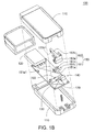
- FIG. 1B shows an explosion diagram of the antenna module in FIG 1A ;
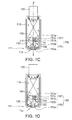
- FIG. 1C shows a top view of the antenna module in FIG 1A when being partially assembled
- FIG 1D shows the actuating member in FIG 1C when being moved towards the USB connecting end.
- FIG. 2 shows a cross-sectional view of the antenna module in FIG. 1C taken along line 2-2';
- FIG. 3A shows a top view of the other antenna module according to the first embodiment of the present invention when being partially assembled.
- FIG. 3B shows the actuating member in FIG 3A when being moved towards the USB connecting end
- FIG. 4A shows a top view of an antenna module according to a second embodiment of the present invention when being partially assembled.
- FIG. 4B shows the moving component in FIG 4A when being moved towards the USB connecting end
- FIG. 5A shows a top view of an antenna module according to a third embodiment of the present invention when being partially assembled
- FIG. 5B shows the actuating member in FIG. 5A when being moved towards the USB connecting end
- the present invention provides an antenna module Under the premises that an antenna is located at a terminal end of a casing and the terminal end is opposite to a USB connecting end, a moving component is disposed at the terminal end of the casing to enable a key of the antenna module.
- the antenna module of the present invention is disclosed below by some embodiments with accompanied drawings. However, the following disclosure is for elaboration only, not for limiting the scope of the present invention Some components are omitted in the diagrams for highlight the technical features of the present invention.
- the present embodiment of the invention discloses an antenna module including a casing, a universal serial bus (USB) connecting end, an antenna, a key and a moving component
- the casing has a terminal end and a hole which is located at the terminal end
- the USB connecting end is opposite to the terminal end
- the antenna is disposed in the casing near the terminal end, and both the key and the moving component are disposed in the casing.
- the key has an enabling portion facing towards the USB connecting end The enabling portion is used for enabling the key when being touched.
- the moving component includes a contacting member and an actuating member
- the contacting member has a first end, a second end and a pivotal portion
- the pivotal portion is pivotally connected to the casing and located between the first end and the second end.
- the second end and the enabling portion are spaced at an interval.
- the actuating member exposed from the hole is used for moving toward the USB connecting end
- the first end is driven by the moving actuating member, so that the second end is rotated around the pivotal portion to touch the enabling portion.
- FIG. 1A an assembly diagram of an antenna module according to a first embodiment of the present invention is shown in FIG. 1A
- an explosion diagram of the antenna module in FIG. 1A is shown in FIG. 1B
- a top view of the antenna module in FIG. 1A when being partially assembled is shown in FIG. 1C .
- the antenna module 100 includes a casing 110, a universal serial bus (USB) connecting end 120, an antenna 130, a key 140 and a moving component 150.
- USB universal serial bus
- the casing 110 is constituted by two housings. Each housing has an indentation When the two housings are assembled together, the two corresponding indentations form a hole 115 at the terminal end 111 of the casing 110 as indicated in FIG. 1A .
- the terminal end 111 is opposite to the USB connecting end 120
- the type of the casing 110 is not limited to the one exemplified above, and any type of casing having a hole at the terminal end opposite to the USB connecting end can be used in the present embodiment of the invention To further highlight the disposition of each components of the antenna module 100, only a part of the casing 110 is illustrated in FIG. 1C .
- the antenna 130 is disposed in the casing 110 Preferably, in order to avoid transmission dead corner formed between the antenna module 100 and an electronic device affecting the transmission efficiency of the antenna 120 when the antenna module 100 is electrically connected to the electronic device through the USB connecting end 120, the antenna 130 is disposed in the casing 100 near the terminal end 111.
- the key 140 is disposed in the casing 110 and has an enabling portion 141
- the enabling portion 141 faces towards the USB connecting end 120 for enabling the key 140 when being touched so as to execute a function corresponding to the key 140.
- the function corresponding to the key 140 can be a function which is used for connecting a wireless network or resetting, but the function is not limited thereto.
- the function corresponding to the key 140 can be determined according to manufacturers' needs.
- the moving component 150 is disposed in the casing 110 and includes a contacting member 151 and an actuating member 153.
- the contacting member 151 has a first end 151a, a second end 151b and a pivotal portion 151c.
- the pivotal portion 151c is pivotally connected to the casing 110 and located between the first end 151a and the second end 151b, so that the first end 151a and the second end 151b can be rotated around the pivotal portion 151c.
- the second end 151b and the enabling portion 141 of the key 140 are spaced at an interval d1. That is, under normal circumstances, the enabling portion 141 of the key 140 does not touch the second end 151b.
- the actuating member 153 has a pressing end 153a and an acting end 153b. The pressing end 153a is opposite to the acting end 153b, and the pressing end 153a is exposed from the hole 115
- the present embodiment is exemplified by the case that the acting end 153b of the actuating member 153 is pivotally connected to the first end 151a of the contacting member 151, and the way of pivotally connecting the acting end 153b of the actuating member 153 to the first end 151a of the contacting member 151 is disclosed below.
- the first end 151a of the contacting member 151 has a pivotal hole 151a1 (shown in FIG..
- the acting end 153b of the actuating member 153 has a pivotal shaft 153b 1 (shown in FIG 1B )
- the pivotal shaft 153b1 is inserted into the pivotal hole 151a1 so as to pivotally connect the contacting member 151 to the actuating member 153.
- the way of pivotally connecting the contacting member 151 to the actuating member 153 is not limited to the exemplification here.
- the movement trace of the first end 151a of the contacting member 151 is similar to an arc, so that the movement of the pivotal shaft 153b1 inserted into the pivotal hole 151a1 of the first end 151a is also similar to an arc
- the pivotal hole 159a1 in FIG 1B is an ellipse, and the position of the pivotal hole 151a1 is determined according to the movement trace of the pivotal shaft 153b1.
- the antenna module 100 of the present embodiment of the invention can further include an elastic member and a light source.
- the design and the disposition of the antenna module 100 including an elastic member and a light source are disclosed below. However, anyone who is skilled in the art should understand that the disposition and the types of the elastic member and the light source are not limited to the following exemplifications
- the enabling portion 141 of the antenna module 100 enables the key 140 when being pressed, and the enabling portion 141 is reboundable, so that the enable portion 141 can restore to its original position after being pressed.
- the enabling portion 141 restores to the original position by an elastic force
- the second end 151b of the contacting member 151 is pushed by the enabling portion 141 to drive the first end 151a to rotate around the pivotal portion 151c to the original position
- the acting end 153b of the actuating member 153 is pushed by the first end 151a of the contacting member 151 to move towards the terminal end 111 Therefore, the acting end 153b restores to the position
- the antenna module 100 can have an elastic member 160 disposed in the casing 110.
- the elastic member 160 is used for providing an elastic force to the actuating member 153, so that the actuating member 153 is moved towards the terminal end 111 to restore to its original position
- the elastic member 160 can be disposed at a position corresponding to the contacting member 151.
- the contacting member 151 When the contacting member 151 restores to its original position by receiving the elastic force provided by the elastic member 160, the contacting member 151 concurrently drives the actuating member 153 to restore to its original position.
- the position, the type, and the quantity of the elastic member 160 or even the way of providing the elastic force to the actuating member 153 are not limited to the above exemplifications
- the elastic member can also be disposed at a position corresponding to the actuating member, so that the actuating member restores to the position as indicated in FIG 1C by an elastic force and the contacting member is concurrently driven to restore to the position as indicated in FIG 1C .
- the antenna module can include two elastic members respectively corresponding to the actuating member and the contacting member. Thus, elastic forces are provided to the actuating member and the contacting member respectively so as to restore the actuating member and the contacting member to the position as indicated in FIG 1C .
- FIG 2 a cross-sectional view of the antenna module in FIG 1C taken along line 2-2' is shown
- the light source 170 such as a light emitting diode (LED)
- LED light emitting diode
- the light source 170 is used for projecting the light into the actuating member 153, so that the light is guided to the outside of the casing 110 by the actuating member 153, as indicated by the arrows in FIG 2 .
- the actuating member 153 has three reflecting members M1, M2 and M3, and the normal direction of the reflecting surface of each reflecting members M1, M2 and M3 and the direction in which the light is projected to the actuating member 153 form an included angle of 45 degrees, for example
- the reflecting member M1 is disposed above the light source 170 for guiding the light towards the reflecting member M2
- the position of the reflecting member M2 corresponds to that of the reflecting member M 1 for receiving the light from the reflecting member M1 and guiding the light towards the reflecting member M3.
- the position of the reflecting member M3 corresponds to those of the reflecting member M2 and the pressing end 153a for receiving the light from the reflecting member M2 and guiding the light towards the pressing end 153a
- the actuating member 153 is made of a transparent material, so that the light can pass through the actuating member 153 and be guided to the outside of the casing 110.
- the projecting area on the pressing end 153a is adjustable, and is not limited to the exemplification here.
- the light source 170 can be used for showing whether the key 140 is enabled by lighting or not, so that a user can understand whether the key 140 is enabled to execute the corresponding function according to the lighting status of the pressing end 153a.
- the application of the light source 170 is not limited to the above exemplifications
- the light source 170 can also continually emit light with certain color under normal circumstances.
- the light source 170 emits light with different color, so that a user can understand whether the key 140 is enabled according to the color change at the pressing end 153a.
- FIG. 3A a top view of the other antenna module according to the first embodiment of the present invention when being partially assembled is shown. Compared with the moving component 150 shown in FIG. 1C , the design of the moving component 250 in FIG 3A is different from that of the moving component 150 in FIG 1C .
- the antenna 230 of the antenna module is disposed in the casing 210 near the terminal end 211.
- the moving component 250 includes a contacting member 251 and an actuating member 253.
- the contacting member 251 has a first end 251 a, a second end 251 b and a pivotal portion 251c.
- the pivotal portion 251c is located between the first end 251 a and the second end 251 b and is pivotally connected to the casing 210.
- the second end 251 b and the enabling portion 241 of the key 240 are spaced at an interval d21. That is, under normal circumstances, the enabling portion 241 of the key 240 does not touch the second end 251 b
- the actuating member 253 has a pressing end 253a and an acting end 253b
- the pressing end 253a is opposite to the acting end 253b, and the pressing end 253a is exposed from a hole 215 located at the terminal end 211 of the casing 210.
- the acting end 253b of the actuating member 253 and the first end 251 a of the contacting member 251 are spaced at an interval d22 That is, under normal circumstances, the actuating member 253 is not directly coupled to the contacting member 251
- the acting end 253b of the actuating member 253 touches and pushes the first end 251 a of the contacting member 251.
- the second end 251 b of the contacting member 251 is rotated around the pivotal portion 251 c to touch the enabling portion 241 to enable the key 240
- the function corresponding to the key 240 such as connecting to a wireless network or resetting, can be executed accordingly.
- the antenna module in FIG 3A and FIG 3B can also be disposed with a light source or/and an elastic member so as to provide corresponding functions
- the disposition and design of the two types of antenna modules disclosed above are only examples for elaboration, but not for limiting the scope of the present invention. Any implementation that the antenna of the antenna module is disposed at the terminal end of the casing, and the key is enabled from the terminal end of the antenna module so as to execute the function corresponding to the key can be used as one of the implementations of the present invention
- the antenna of the antenna module is disposed near the terminal end of the casing to avoid the signal transmitted by the antenna being affected by the transmission dead corner formed between the antenna module and an electronic device electrically connected thereto.
- the contacting member is driven by the actuating member disposed at the terminal end to enable the key.
- the antenna module of the present embodiment of the invention provides the design of disposing the antenna and the mechanism for enabling the key at the terminal end of the casing concurrently.
- receptacles provided for the USB connecting end of the antenna module to be inserted therein are stacked at an electronic device.
- the antenna module of the present embodiment of the invention Compared with the antenna module in which the antenna is disposed at the terminal end of the casing and the key can only be disposed at the side of the casing, the antenna module of the present embodiment of the invention has the following advantages. Firstly, the antenna module of the present embodiment of the invention provides excellent quality in signal transmission. Secondly, despite a number of antenna modules of the present embodiment of the invention are inserted into stacked receptacles concurrently, the antenna module of the present embodiment of the invention still allows a user to conveniently enable the key through the moving component located at the terminal end, and the situation that the antenna module with the key at the side is likely blocked by other antenna modules can be avoided.
- the disposition of the key and the design of the moving component of the antenna module of the present embodiment of the invention are different from those of the antenna module of the first embodiment.
- FIG. 4A a top view of an antenna module according to a second embodiment of the present invention when being partially assembled is shown
- the antenna 330 of the antenna module is disposed in the casing 310 near the terminal end 311.
- the key 340 and the moving component 350 are disposed in the casing 310.
- the key 340 has an enabling portion 341 facing the terminal end 311 of the casing 310 for enabling the key 340 when being touched
- the moving component 350 has a pressing end 350a and an acting end 350b.
- the pressing end 350a is opposite to the acting end 350b, and the pressing end 350a is exposed from the hole 315 located at the terminal end 311.
- the acting end 350b and the enabling portion 341 are spaced at an interval d3 That is, under normal circumstances, the enabling portion 341 of the key 340 does not touch the acting end 350b
- the acting end 350b touches the enabling portion 341 (as indicated in FIG 4B ) to enable the key 340.
- the function corresponding to the key 340 such as connecting to a wireless network or resetting, can be executed accordingly.
- the antenna modules in FIG. 4A and FIG. 4B can further include a light source and an elastic member as indicated in the first embodiment according to the needs
- the design of the light source and the elastic member is disclosed in the first embodiment, and is not repeatedly described herein.
- the disposition and design of the antenna module disclosed above are only an exemplification for elaboration, not for limiting the scope of the present invention Any implementation that the antenna of the antenna module is disposed at the terminal end of the casing, and the key is enabled from the terminal end of the antenna module so as to execute the function corresponding to the key can be used as one of the implementations of the present invention
- the antenna of the antenna module is disposed near the terminal end of the casing to avoid the signal transmitted by the antenna being affected by the transmission dead corner formed between the antenna module and an electronic device electrically connected thereto
- the contacting member is driven by the moving component disposed at the terminal end to enable the key
- the antenna module of the present embodiment of the invention provides the design of disposing the antenna and the mechanism for enabling the key at the terminal end of the casing concurrently
- a user still can enable the key through the moving component located at the terminal end, and the situation that the antenna module with the key at the side is likely blocked by other antenna modules can be avoided.
- the design of the moving component of the antenna module of the present embodiment of the invention is different from that of the first embodiment
- FIG 5A a top view of an antenna module according to a third embodiment of the present invention when being partially assembled is shown
- the antenna 430 of the antenna module is disposed in the casing 410 near the terminal end 411.
- the key 440 and the moving component 450 are disposed in the casing 410
- the key 440 has an enabling portion 441 facing the USB connecting end 412 for enabling the key when being touched 440.
- the USB connecting end 412 is opposite to the terminal end 411.
- the moving component 450 includes a contacting member 451 and an actuating member 453
- the contacting member 451 is a U-shaped structure and has a first end 451 a and a second end 451b.
- the first end 451 a and the second end 451 b face the terminal end 411.
- the second end 451 b and the enabling portion 441 are spaced at an interval d4 That is, under normal circumstances, the enabling portion 441 of the key 440 does not touch the second end 451b.
- the actuating member 453 has a pressing end 453a and an acting end 453b.
- the pressing end 453a is opposite to the acting end 453b, and the pressing end 453a is exposed from the hole 415
- the acting end 453b of the actuating member 453 is connected to the first end 451a of the contacting member 451, and the contacting member 451 and the actuating member 453 can be integrally formed.
- the antenna module in FIG. 5A and FIG. 5B can further include a light source and an elastic member as indicated in the first embodiment according to the needs.
- the design of the light source and the elastic member is disclosed in the first embodiment, and is not repeatedly described herein.
- the disposition and design of the antenna module disclosed above are only an exemplification for elaboration, not for limiting the scope of the present invention. Any implementation that the antenna of the antenna module is disposed at the terminal end of the casing, and the key is enabled from the terminal end of the antenna module so as to execute the function corresponding to the key can be used as one of the implementations of the present invention.
- the key is enabled by the moving component disposed at the terminal end of the casing.
- the transmission efficiency is improved.
- the user still can conveniently enable the key through the moving component located at the terminal end, and the situation that the antenna module with the key at the side is likely blocked by other antenna modules can be avoided.
Landscapes
- Engineering & Computer Science (AREA)
- Computer Networks & Wireless Communication (AREA)
- Signal Processing (AREA)
- Telephone Set Structure (AREA)
- Support Of Aerials (AREA)
Applications Claiming Priority (1)
| Application Number | Priority Date | Filing Date | Title |
|---|---|---|---|
| TW097134680A TWI380503B (en) | 2008-09-10 | 2008-09-10 | Antenna module |
Publications (3)
| Publication Number | Publication Date |
|---|---|
| EP2164082A2 true EP2164082A2 (de) | 2010-03-17 |
| EP2164082A3 EP2164082A3 (de) | 2010-08-04 |
| EP2164082B1 EP2164082B1 (de) | 2011-08-24 |
Family
ID=41394050
Family Applications (1)
| Application Number | Title | Priority Date | Filing Date |
|---|---|---|---|
| EP09168599A Not-in-force EP2164082B1 (de) | 2008-09-10 | 2009-08-25 | Antennenmodul |
Country Status (4)
| Country | Link |
|---|---|
| US (1) | US8305288B2 (de) |
| EP (1) | EP2164082B1 (de) |
| AT (1) | ATE521976T1 (de) |
| TW (1) | TWI380503B (de) |
Families Citing this family (4)
| Publication number | Priority date | Publication date | Assignee | Title |
|---|---|---|---|---|
| CN101697378B (zh) * | 2009-10-30 | 2012-11-21 | 华为终端有限公司 | 无线设备天线处理方法以及无线设备 |
| CN201718153U (zh) * | 2010-06-11 | 2011-01-19 | 华为终端有限公司 | 一种旋转数据卡 |
| TWI406122B (zh) * | 2010-12-13 | 2013-08-21 | Ability Entpr Co Ltd | 訊號傳輸模組 |
| DE102015113114B4 (de) | 2015-08-10 | 2018-11-15 | E.E.P.D. - Electronic-Equipment-Produktion & Distribution Gmbh | Sicherungsrahmen für einen USB-Anschluss, USB-Verteiler und Steckermodul |
Family Cites Families (14)
| Publication number | Priority date | Publication date | Assignee | Title |
|---|---|---|---|---|
| DE3670174D1 (de) | 1985-10-16 | 1990-05-10 | Fujitsu Ltd | Drucktastenschalter mit gekruemmten scheibenfedern. |
| JPH06162871A (ja) | 1992-11-25 | 1994-06-10 | Ricoh Co Ltd | 電源スイッチ機構 |
| TW324886U (en) | 1996-12-11 | 1998-01-11 | Wen-Zhang Lan | Fly catcher |
| US6394813B1 (en) * | 2000-09-08 | 2002-05-28 | 3Com Corporation | Rotating connector adaptor |
| US6816121B1 (en) * | 2003-06-18 | 2004-11-09 | Benq Corporation | Motorized rotatable wireless antenna |
| US7632113B2 (en) * | 2003-11-17 | 2009-12-15 | Dpd Patent Trust Ltd. | Retractable USB stick |
| JP2006221845A (ja) | 2005-02-08 | 2006-08-24 | Funai Electric Co Ltd | 面押しボタン及び電子機器 |
| JP2007173172A (ja) * | 2005-12-26 | 2007-07-05 | Omron Corp | 押釦スイッチ |
| JP4965196B2 (ja) | 2006-08-29 | 2012-07-04 | Idec株式会社 | 押ボタンスイッチ装置 |
| TWM324886U (en) | 2007-06-29 | 2008-01-01 | Cheng Uei Prec Ind Co Ltd | USB bluetooth connector |
| US7470148B1 (en) * | 2007-07-17 | 2008-12-30 | Cheng Uei Precision Industry Co., Ltd. | USB bluetooth connector |
| US7586460B2 (en) * | 2007-10-15 | 2009-09-08 | Sony Ericsson Mobile Communications Ab | Dongle device with integrated antenna assembly |
| US7530823B1 (en) * | 2008-01-07 | 2009-05-12 | Sony Ericsson Mobile Communications Ab | USB modem devices with a flip antenna and a retractable USB connector |
| KR101084765B1 (ko) * | 2010-01-27 | 2011-11-22 | 주식회사 팬택 | Usb타입의 무선 데이터 카드 |
-
2008
- 2008-09-10 TW TW097134680A patent/TWI380503B/zh not_active IP Right Cessation
-
2009
- 2009-08-19 US US12/543,716 patent/US8305288B2/en not_active Expired - Fee Related
- 2009-08-25 EP EP09168599A patent/EP2164082B1/de not_active Not-in-force
- 2009-08-25 AT AT09168599T patent/ATE521976T1/de not_active IP Right Cessation
Also Published As
| Publication number | Publication date |
|---|---|
| TW201011976A (en) | 2010-03-16 |
| TWI380503B (en) | 2012-12-21 |
| EP2164082A3 (de) | 2010-08-04 |
| EP2164082B1 (de) | 2011-08-24 |
| US8305288B2 (en) | 2012-11-06 |
| ATE521976T1 (de) | 2011-09-15 |
| US20100060533A1 (en) | 2010-03-11 |
Similar Documents
| Publication | Publication Date | Title |
|---|---|---|
| CN104656802B (zh) | 固定机构及其外接式电子装置 | |
| US8657619B2 (en) | Fixing mechanism for fixing a board and electronic device therewith | |
| US8337222B2 (en) | Connector socket and portable electronic device using the same | |
| US9229473B2 (en) | Portable keyboard | |
| US7726987B2 (en) | Card fixer | |
| US20130286562A1 (en) | Electronic device | |
| EP2164082B1 (de) | Antennenmodul | |
| US20150188636A1 (en) | Optical transceiver | |
| CN203812161U (zh) | 锁固装置与扩充座 | |
| US8982551B2 (en) | Electronic device and electronic module fixing structure thereof | |
| US8246380B2 (en) | Connecting device | |
| US8840416B2 (en) | Portable electronic device | |
| US20160064874A1 (en) | Board connection structure and electronic device | |
| TWM443884U (en) | Illuminating keyboard device | |
| CN102279619A (zh) | 电子设备 | |
| US9322985B1 (en) | Light emitting structure around a keyboard backlight module | |
| CN102402248A (zh) | 电子装置 | |
| US7975368B2 (en) | Wireless receiver structure | |
| TWI564789B (zh) | 電子裝置、連接模組、聲音輸出單元以及音訊輸出的切換方法 | |
| CN101728625B (zh) | 天线模块 | |
| TWM547745U (zh) | 發光鍵盤及使用其之電子裝置 | |
| CN219203683U (zh) | 一种线缆连接器 | |
| JP2013069640A (ja) | スイッチ装置、並びにこれを備えた表示装置および電子機器 | |
| JP2010224326A (ja) | 携帯機器 | |
| KR100786157B1 (ko) | 버튼장치 및 이를 구비한 모바일기기 |
Legal Events
| Date | Code | Title | Description |
|---|---|---|---|
| PUAI | Public reference made under article 153(3) epc to a published international application that has entered the european phase |
Free format text: ORIGINAL CODE: 0009012 |
|
| AK | Designated contracting states |
Kind code of ref document: A2 Designated state(s): AT BE BG CH CY CZ DE DK EE ES FI FR GB GR HR HU IE IS IT LI LT LU LV MC MK MT NL NO PL PT RO SE SI SK SM TR |
|
| AX | Request for extension of the european patent |
Extension state: AL BA RS |
|
| PUAL | Search report despatched |
Free format text: ORIGINAL CODE: 0009013 |
|
| AK | Designated contracting states |
Kind code of ref document: A3 Designated state(s): AT BE BG CH CY CZ DE DK EE ES FI FR GB GR HR HU IE IS IT LI LT LU LV MC MK MT NL NO PL PT RO SE SI SK SM TR |
|
| AX | Request for extension of the european patent |
Extension state: AL BA RS |
|
| RIC1 | Information provided on ipc code assigned before grant |
Ipc: H04B 1/034 20060101ALI20100630BHEP Ipc: H01R 13/66 20060101ALI20100630BHEP Ipc: H01Q 1/22 20060101ALI20100630BHEP Ipc: H01H 13/02 20060101ALI20100630BHEP Ipc: H01R 13/70 20060101ALI20100630BHEP Ipc: H01H 3/38 20060101AFI20091214BHEP Ipc: H01H 3/46 20060101ALI20100630BHEP |
|
| GRAP | Despatch of communication of intention to grant a patent |
Free format text: ORIGINAL CODE: EPIDOSNIGR1 |
|
| 17P | Request for examination filed |
Effective date: 20110128 |
|
| RIC1 | Information provided on ipc code assigned before grant |
Ipc: H01H 3/46 20060101ALI20110224BHEP Ipc: H01H 13/02 20060101ALI20110224BHEP Ipc: H01R 13/70 20060101ALI20110224BHEP Ipc: H01R 13/66 20060101ALI20110224BHEP Ipc: H04B 1/034 20060101ALI20110224BHEP Ipc: H01Q 1/22 20060101ALI20110224BHEP Ipc: H01H 3/38 20060101AFI20110224BHEP |
|
| GRAS | Grant fee paid |
Free format text: ORIGINAL CODE: EPIDOSNIGR3 |
|
| GRAA | (expected) grant |
Free format text: ORIGINAL CODE: 0009210 |
|
| AK | Designated contracting states |
Kind code of ref document: B1 Designated state(s): AT BE BG CH CY CZ DE DK EE ES FI FR GB GR HR HU IE IS IT LI LT LU LV MC MK MT NL NO PL PT RO SE SI SK SM TR |
|
| REG | Reference to a national code |
Ref country code: GB Ref legal event code: FG4D |
|
| REG | Reference to a national code |
Ref country code: CH Ref legal event code: EP |
|
| REG | Reference to a national code |
Ref country code: IE Ref legal event code: FG4D |
|
| REG | Reference to a national code |
Ref country code: DE Ref legal event code: R096 Ref document number: 602009002248 Country of ref document: DE Effective date: 20111020 |
|
| REG | Reference to a national code |
Ref country code: NL Ref legal event code: VDEP Effective date: 20110824 |
|
| PG25 | Lapsed in a contracting state [announced via postgrant information from national office to epo] |
Ref country code: MT Free format text: LAPSE BECAUSE OF FAILURE TO SUBMIT A TRANSLATION OF THE DESCRIPTION OR TO PAY THE FEE WITHIN THE PRESCRIBED TIME-LIMIT Effective date: 20110824 |
|
| LTIE | Lt: invalidation of european patent or patent extension |
Effective date: 20110824 |
|
| PG25 | Lapsed in a contracting state [announced via postgrant information from national office to epo] |
Ref country code: NL Free format text: LAPSE BECAUSE OF FAILURE TO SUBMIT A TRANSLATION OF THE DESCRIPTION OR TO PAY THE FEE WITHIN THE PRESCRIBED TIME-LIMIT Effective date: 20110824 Ref country code: SE Free format text: LAPSE BECAUSE OF FAILURE TO SUBMIT A TRANSLATION OF THE DESCRIPTION OR TO PAY THE FEE WITHIN THE PRESCRIBED TIME-LIMIT Effective date: 20110824 Ref country code: PT Free format text: LAPSE BECAUSE OF FAILURE TO SUBMIT A TRANSLATION OF THE DESCRIPTION OR TO PAY THE FEE WITHIN THE PRESCRIBED TIME-LIMIT Effective date: 20111226 Ref country code: NO Free format text: LAPSE BECAUSE OF FAILURE TO SUBMIT A TRANSLATION OF THE DESCRIPTION OR TO PAY THE FEE WITHIN THE PRESCRIBED TIME-LIMIT Effective date: 20111124 Ref country code: FI Free format text: LAPSE BECAUSE OF FAILURE TO SUBMIT A TRANSLATION OF THE DESCRIPTION OR TO PAY THE FEE WITHIN THE PRESCRIBED TIME-LIMIT Effective date: 20110824 Ref country code: LT Free format text: LAPSE BECAUSE OF FAILURE TO SUBMIT A TRANSLATION OF THE DESCRIPTION OR TO PAY THE FEE WITHIN THE PRESCRIBED TIME-LIMIT Effective date: 20110824 Ref country code: HR Free format text: LAPSE BECAUSE OF FAILURE TO SUBMIT A TRANSLATION OF THE DESCRIPTION OR TO PAY THE FEE WITHIN THE PRESCRIBED TIME-LIMIT Effective date: 20110824 Ref country code: IS Free format text: LAPSE BECAUSE OF FAILURE TO SUBMIT A TRANSLATION OF THE DESCRIPTION OR TO PAY THE FEE WITHIN THE PRESCRIBED TIME-LIMIT Effective date: 20111224 |
|
| REG | Reference to a national code |
Ref country code: AT Ref legal event code: MK05 Ref document number: 521976 Country of ref document: AT Kind code of ref document: T Effective date: 20110824 |
|
| PG25 | Lapsed in a contracting state [announced via postgrant information from national office to epo] |
Ref country code: AT Free format text: LAPSE BECAUSE OF FAILURE TO SUBMIT A TRANSLATION OF THE DESCRIPTION OR TO PAY THE FEE WITHIN THE PRESCRIBED TIME-LIMIT Effective date: 20110824 Ref country code: SI Free format text: LAPSE BECAUSE OF FAILURE TO SUBMIT A TRANSLATION OF THE DESCRIPTION OR TO PAY THE FEE WITHIN THE PRESCRIBED TIME-LIMIT Effective date: 20110824 Ref country code: CY Free format text: LAPSE BECAUSE OF FAILURE TO SUBMIT A TRANSLATION OF THE DESCRIPTION OR TO PAY THE FEE WITHIN THE PRESCRIBED TIME-LIMIT Effective date: 20110824 Ref country code: LV Free format text: LAPSE BECAUSE OF FAILURE TO SUBMIT A TRANSLATION OF THE DESCRIPTION OR TO PAY THE FEE WITHIN THE PRESCRIBED TIME-LIMIT Effective date: 20110824 Ref country code: GR Free format text: LAPSE BECAUSE OF FAILURE TO SUBMIT A TRANSLATION OF THE DESCRIPTION OR TO PAY THE FEE WITHIN THE PRESCRIBED TIME-LIMIT Effective date: 20111125 Ref country code: PL Free format text: LAPSE BECAUSE OF FAILURE TO SUBMIT A TRANSLATION OF THE DESCRIPTION OR TO PAY THE FEE WITHIN THE PRESCRIBED TIME-LIMIT Effective date: 20110824 |
|
| PG25 | Lapsed in a contracting state [announced via postgrant information from national office to epo] |
Ref country code: BE Free format text: LAPSE BECAUSE OF FAILURE TO SUBMIT A TRANSLATION OF THE DESCRIPTION OR TO PAY THE FEE WITHIN THE PRESCRIBED TIME-LIMIT Effective date: 20110824 Ref country code: MC Free format text: LAPSE BECAUSE OF NON-PAYMENT OF DUE FEES Effective date: 20110831 |
|
| PG25 | Lapsed in a contracting state [announced via postgrant information from national office to epo] |
Ref country code: CZ Free format text: LAPSE BECAUSE OF FAILURE TO SUBMIT A TRANSLATION OF THE DESCRIPTION OR TO PAY THE FEE WITHIN THE PRESCRIBED TIME-LIMIT Effective date: 20110824 Ref country code: SK Free format text: LAPSE BECAUSE OF FAILURE TO SUBMIT A TRANSLATION OF THE DESCRIPTION OR TO PAY THE FEE WITHIN THE PRESCRIBED TIME-LIMIT Effective date: 20110824 |
|
| REG | Reference to a national code |
Ref country code: IE Ref legal event code: MM4A |
|
| PG25 | Lapsed in a contracting state [announced via postgrant information from national office to epo] |
Ref country code: IT Free format text: LAPSE BECAUSE OF FAILURE TO SUBMIT A TRANSLATION OF THE DESCRIPTION OR TO PAY THE FEE WITHIN THE PRESCRIBED TIME-LIMIT Effective date: 20110824 Ref country code: EE Free format text: LAPSE BECAUSE OF FAILURE TO SUBMIT A TRANSLATION OF THE DESCRIPTION OR TO PAY THE FEE WITHIN THE PRESCRIBED TIME-LIMIT Effective date: 20110824 Ref country code: RO Free format text: LAPSE BECAUSE OF FAILURE TO SUBMIT A TRANSLATION OF THE DESCRIPTION OR TO PAY THE FEE WITHIN THE PRESCRIBED TIME-LIMIT Effective date: 20110824 |
|
| PG25 | Lapsed in a contracting state [announced via postgrant information from national office to epo] |
Ref country code: DK Free format text: LAPSE BECAUSE OF FAILURE TO SUBMIT A TRANSLATION OF THE DESCRIPTION OR TO PAY THE FEE WITHIN THE PRESCRIBED TIME-LIMIT Effective date: 20110824 |
|
| PLBE | No opposition filed within time limit |
Free format text: ORIGINAL CODE: 0009261 |
|
| STAA | Information on the status of an ep patent application or granted ep patent |
Free format text: STATUS: NO OPPOSITION FILED WITHIN TIME LIMIT |
|
| PG25 | Lapsed in a contracting state [announced via postgrant information from national office to epo] |
Ref country code: IE Free format text: LAPSE BECAUSE OF NON-PAYMENT OF DUE FEES Effective date: 20110825 |
|
| 26N | No opposition filed |
Effective date: 20120525 |
|
| REG | Reference to a national code |
Ref country code: DE Ref legal event code: R097 Ref document number: 602009002248 Country of ref document: DE Effective date: 20120525 |
|
| PG25 | Lapsed in a contracting state [announced via postgrant information from national office to epo] |
Ref country code: MK Free format text: LAPSE BECAUSE OF FAILURE TO SUBMIT A TRANSLATION OF THE DESCRIPTION OR TO PAY THE FEE WITHIN THE PRESCRIBED TIME-LIMIT Effective date: 20110824 |
|
| PG25 | Lapsed in a contracting state [announced via postgrant information from national office to epo] |
Ref country code: SM Free format text: LAPSE BECAUSE OF FAILURE TO SUBMIT A TRANSLATION OF THE DESCRIPTION OR TO PAY THE FEE WITHIN THE PRESCRIBED TIME-LIMIT Effective date: 20110824 Ref country code: ES Free format text: LAPSE BECAUSE OF FAILURE TO SUBMIT A TRANSLATION OF THE DESCRIPTION OR TO PAY THE FEE WITHIN THE PRESCRIBED TIME-LIMIT Effective date: 20111205 |
|
| PG25 | Lapsed in a contracting state [announced via postgrant information from national office to epo] |
Ref country code: LU Free format text: LAPSE BECAUSE OF NON-PAYMENT OF DUE FEES Effective date: 20110825 |
|
| PG25 | Lapsed in a contracting state [announced via postgrant information from national office to epo] |
Ref country code: BG Free format text: LAPSE BECAUSE OF FAILURE TO SUBMIT A TRANSLATION OF THE DESCRIPTION OR TO PAY THE FEE WITHIN THE PRESCRIBED TIME-LIMIT Effective date: 20111124 |
|
| PG25 | Lapsed in a contracting state [announced via postgrant information from national office to epo] |
Ref country code: TR Free format text: LAPSE BECAUSE OF FAILURE TO SUBMIT A TRANSLATION OF THE DESCRIPTION OR TO PAY THE FEE WITHIN THE PRESCRIBED TIME-LIMIT Effective date: 20110824 |
|
| PG25 | Lapsed in a contracting state [announced via postgrant information from national office to epo] |
Ref country code: HU Free format text: LAPSE BECAUSE OF FAILURE TO SUBMIT A TRANSLATION OF THE DESCRIPTION OR TO PAY THE FEE WITHIN THE PRESCRIBED TIME-LIMIT Effective date: 20110824 |
|
| REG | Reference to a national code |
Ref country code: CH Ref legal event code: PL |
|
| PG25 | Lapsed in a contracting state [announced via postgrant information from national office to epo] |
Ref country code: CH Free format text: LAPSE BECAUSE OF NON-PAYMENT OF DUE FEES Effective date: 20130831 Ref country code: LI Free format text: LAPSE BECAUSE OF NON-PAYMENT OF DUE FEES Effective date: 20130831 |
|
| REG | Reference to a national code |
Ref country code: FR Ref legal event code: PLFP Year of fee payment: 8 |
|
| PGFP | Annual fee paid to national office [announced via postgrant information from national office to epo] |
Ref country code: DE Payment date: 20160830 Year of fee payment: 8 Ref country code: GB Payment date: 20160810 Year of fee payment: 8 |
|
| PGFP | Annual fee paid to national office [announced via postgrant information from national office to epo] |
Ref country code: FR Payment date: 20160810 Year of fee payment: 8 |
|
| REG | Reference to a national code |
Ref country code: DE Ref legal event code: R119 Ref document number: 602009002248 Country of ref document: DE |
|
| GBPC | Gb: european patent ceased through non-payment of renewal fee |
Effective date: 20170825 |
|
| REG | Reference to a national code |
Ref country code: FR Ref legal event code: ST Effective date: 20180430 |
|
| PG25 | Lapsed in a contracting state [announced via postgrant information from national office to epo] |
Ref country code: GB Free format text: LAPSE BECAUSE OF NON-PAYMENT OF DUE FEES Effective date: 20170825 Ref country code: DE Free format text: LAPSE BECAUSE OF NON-PAYMENT OF DUE FEES Effective date: 20180301 |
|
| PG25 | Lapsed in a contracting state [announced via postgrant information from national office to epo] |
Ref country code: FR Free format text: LAPSE BECAUSE OF NON-PAYMENT OF DUE FEES Effective date: 20170831 |