EP2164151A2 - Tragbares Netz- und Steuergerät - Google Patents
Tragbares Netz- und Steuergerät Download PDFInfo
- Publication number
- EP2164151A2 EP2164151A2 EP09158914A EP09158914A EP2164151A2 EP 2164151 A2 EP2164151 A2 EP 2164151A2 EP 09158914 A EP09158914 A EP 09158914A EP 09158914 A EP09158914 A EP 09158914A EP 2164151 A2 EP2164151 A2 EP 2164151A2
- Authority
- EP
- European Patent Office
- Prior art keywords
- enclosure
- bicycle
- control pack
- electric power
- portable power
- Prior art date
- Legal status (The legal status is an assumption and is not a legal conclusion. Google has not performed a legal analysis and makes no representation as to the accuracy of the status listed.)
- Withdrawn
Links
Images


Classifications
-
- B—PERFORMING OPERATIONS; TRANSPORTING
- B62—LAND VEHICLES FOR TRAVELLING OTHERWISE THAN ON RAILS
- B62M—RIDER PROPULSION OF WHEELED VEHICLES OR SLEDGES; POWERED PROPULSION OF SLEDGES OR SINGLE-TRACK CYCLES; TRANSMISSIONS SPECIALLY ADAPTED FOR SUCH VEHICLES
- B62M6/00—Rider propulsion of wheeled vehicles with additional source of power, e.g. combustion engine or electric motor
- B62M6/80—Accessories, e.g. power sources; Arrangements thereof
- B62M6/90—Batteries
-
- B—PERFORMING OPERATIONS; TRANSPORTING
- B62—LAND VEHICLES FOR TRAVELLING OTHERWISE THAN ON RAILS
- B62J—CYCLE SADDLES OR SEATS; AUXILIARY DEVICES OR ACCESSORIES SPECIALLY ADAPTED TO CYCLES AND NOT OTHERWISE PROVIDED FOR, e.g. ARTICLE CARRIERS OR CYCLE PROTECTORS
- B62J43/00—Arrangements of batteries
- B62J43/10—Arrangements of batteries for propulsion
- B62J43/13—Arrangements of batteries for propulsion on rider-propelled cycles with additional electric propulsion
-
- H—ELECTRICITY
- H01—ELECTRIC ELEMENTS
- H01M—PROCESSES OR MEANS, e.g. BATTERIES, FOR THE DIRECT CONVERSION OF CHEMICAL ENERGY INTO ELECTRICAL ENERGY
- H01M10/00—Secondary cells; Manufacture thereof
- H01M10/42—Methods or arrangements for servicing or maintenance of secondary cells or secondary half-cells
-
- Y—GENERAL TAGGING OF NEW TECHNOLOGICAL DEVELOPMENTS; GENERAL TAGGING OF CROSS-SECTIONAL TECHNOLOGIES SPANNING OVER SEVERAL SECTIONS OF THE IPC; TECHNICAL SUBJECTS COVERED BY FORMER USPC CROSS-REFERENCE ART COLLECTIONS [XRACs] AND DIGESTS
- Y02—TECHNOLOGIES OR APPLICATIONS FOR MITIGATION OR ADAPTATION AGAINST CLIMATE CHANGE
- Y02E—REDUCTION OF GREENHOUSE GAS [GHG] EMISSIONS, RELATED TO ENERGY GENERATION, TRANSMISSION OR DISTRIBUTION
- Y02E60/00—Enabling technologies; Technologies with a potential or indirect contribution to GHG emissions mitigation
- Y02E60/10—Energy storage using batteries
Definitions
- the present invention relates to electric power packs. More particularly, the present invention relates to a portable control pack complete with an electric power device and easily mountable on a human-powered bicycle with an axle motor so as to convert the bicycle into an electrically driven bicycle.
- Bicycles were invented in the first place as a means of transportation and have thrived again in recent years due to the gradual depletion of energy reserve and global warming. Although not limited by gender or age, riding a bicycle can nevertheless be physically demanding, especially when it comes to coping with different road conditions. For example, riding uphill is undoubtedly an arduous task for seniors or those who do not exercise regularly. In order to solve this problem, electrically driven bicycles that require no pedaling have emerged.
- a typical electric bicycle has an electric power device fixedly mounted on the bicycle frame and electrically connected to an axle motor of the wheels so as to drive the bicycle forward. When it is desired to drive the bicycle by pedaling, power transmission from the electric power device can be cut off.
- the aforesaid electric bicycle has the following disadvantages.
- the heavy and bulky batteries and electric power device are immovably attached to the bicycle frame and thus become an unnecessary burden to the cyclist during the human-powered mode.
- the electric power device is integrally formed with the bicycle frame, recharging cannot be done without moving the entire bicycle to a charging power source and is thus extremely inconvenient.
- the electric power device by making the electric power device an inseparable part of the bicycle, the selling price, as well as the risk of theft, of the bicycle is increased, only to cause more trouble to consumers and bicycle owners.
- the present invention provides a portable power and control pack.
- the power and control pack includes an enclosure in which an electric power device and a controller electrically connected thereto are disposed.
- the enclosure has a top surface and a lateral surface formed respectively with openings.
- the enclosure has a frontal surface provided with at least one connecting element.
- the electric power device has a lateral surface provided with a plurality of connectors corresponding in position to one of the openings of the enclosure.
- the power and control pack disclosed herein can be conveniently mounted, by means of the at least one connecting element on the enclosure, on a bicycle having an axle motor, thus allowing the connectors of the electric power device to be connected to the axle motor of the bicycle via transmission lines.
- an ordinary human-powered bicycle that is driven by pedaling is readily transformed into an electrically driven bicycle.
- the power and control pack can be easily detached from the bicycle to reduce the overall weight of the bicycle so that no extra burden will be imposed on pedaling.
- the power and control pack can be removed from the bicycle when the electric power device needs charging or when the cyclist has to leave the bicycle. Consequently, charging is made easy, and the risk of the bicycle's being stolen is lowered.
- the present invention is capable of overcoming all the above-mentioned disadvantages of the conventional electric bicycle.
- each of the openings of the enclosure includes a flippable cover plate that is connected to the corresponding opening by a zipper.
- the at least one connecting element provided on the frontal surface of the enclosure may include a fastener, a hook, or a combination thereof, wherein the fastener and the hook are provided at arbitrary locations on the same side or different sides of the enclosure.
- the plurality of connecters on the lateral surface of the electric power device include a sensing connector, a charging connector, and an electric power output connector.
- the plurality of connectors may include an LED display connector, a pedal counter connector, or a brake detection connector.
- the enclosure may be further provided with a strap connected to two opposite lateral surfaces of the enclosure.
- the enclosure is preferably made of a waterproof material so as to adapt to the outdoor environment where bicycles are generally used.
- the disclosed portable power and control pack is equally applicable to handheld mowing machines, motor-powered sampans, or other devices to be driven by low-capacity electric power supplies.
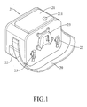
- the portable power and control pack includes an enclosure 2 preferably made of a waterproof material so as to cope with the outdoor environment where bicycles are generally used.
- the enclosure 2 is provided with a strap 20 connected to two opposite lateral surfaces of the enclosure 2.
- the enclosure 2 has a top surface and a lateral surface provided with flippable cover plates 21 and 22, respectively. When the cover plates 21 and 22 are flipped open, two openings 210 and 220 are formed on the enclosure 2.
- the cover plates 21 and 22 can be connected to the openings 210 and 220 by elements such as zippers or, as shown in the present embodiment, by being affixed near the openings 210 and 220 such that the cover plates 21 and 22 are only allowed to be flipped open but not completely removed.
- the cover plate 21 in the present embodiment is formed with a window 211 which is hollow or covered with a transparent plate.
- a fastener 23 and a pair of bilaterally arranged hooks 25 are provided on a frontal surface of the enclosure 2.
- the fastener 23 is configured for fastening with a fastening element 24 on a handlebar 31 of a bicycle 3 (see FIG. 3 ) while the hooks 25 are configured for hooking on a rear rack 32 of the bicycle 3 (see FIG. 4 ).
- the fastener 23 and the hooks 25 described above are preferred embodiments for illustrative purposes only and may vary in structure, quantity, and location so as to suit the portions of a bicycle to which they are applied and the corresponding fastening elements
- An electric power device 26 and a controller 27 electrically connected thereto are disposed in the enclosure 2.
- the controller 27 can be assembled to the electric power device 26 to form one piece.
- the controller 27 is mounted on a top of the electric power device 26 and corresponds in position to the upper opening 210 of the enclosure 2.
- a power switch 261 of the electric power device 26 is also exposed in the opening 210 so that, when the opening 210 is covered by the cover plate 21, the power switch 261 corresponds in position exactly to the window 211 of the cover plate 21, thus allowing the power switch 261 to be easily viewed and operated.
- the electric power device 26 has a lateral surface provided with a plurality of connectors, which in the present embodiment at least include a sensing connector 262, a charging connector 263, and an electric power output connector 264. These connectors correspond in position to the opening 220 of the enclosure 2 so as to be easily connected by transmission lines to a corresponding device (such as an axle motor) of a bicycle after the cover plate 22 is flipped open.
- a corresponding device such as an axle motor
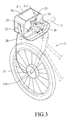
- FIG.3 and FIG. 4 for schematic drawings showing the portable power and control pack of the present invention applied to a bicycle 3.
- a wheel 33 having an axle motor 331 is installed in the bicycle 3 as the front wheel
- the power and control pack is fastened to a fastening element 24 on a handlebar 31 of the bicycle 3 by means of the fastener 23 on the frontal surface of the enclosure 2.
- the power and control pack is electrically connected to the axle motor 331 by a transmission line 28 so that the axle motor 331 is driven by electric power coming from the power and control pack.
- the bicycle 3 is transformed from one purely powered by pedaling into one driven by electricity.
- the power and control pack is hooked on a periphery of a rear rack 32 of the bicycle 3 by means of the pair of hooks 25, before the power and control pack is electrically connected by the transmission line 28 to the axle motor 331.
- the power and control pack can be mounted on the handlebar or the rear rack of a bicycle regardless of whether the axle motor is installed on the front wheel or the rear wheel of the bicycle because the power and control pack can in either case be connected to the axle motor by a transmission line of sufficient length.
- a transmission line longer than required in the case described in the previous paragraph can be used to electrically connect the power and control pack mounted on the handlebar 31 of the bicycle 3 to the axle motor 331 installed at the rear wheel of the bicycle 3, or to electrically connect the power and control pack mounted on the rear rack 32 of the bicycle 3 to the axle motor 331 installed at the front wheel of the bicycle 3.
- the axle motor 331 can be installed on any appropriate part of the bicycle 3 other than the handlebar 31 and the rear rack 32.
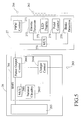
- FIG. 5 is a block diagram of the electric power device 26 and the controller 27 electrically connected thereto that are disposed in the portable power and control pack according to the present invention.
- the electric power device 26 includes a battery 265 (such as a lithium battery used in the present embodiment) and a battery management system (BMS) 266.
- the battery management system 266 includes a micro control unit (MCU) 2661, a balance circuitry 2662, a power output control unit 2663, and a charger control unit 2664.
- the controller 27 in the present embodiment includes a PWM control unit 271 and a throttle detection unit 272.
- the micro control unit 2661 of the battery management system 266 controls the balance circuitry 2662 and the power output control unit 2663 so as to transmit electric power through the PWM control unit 271 of the controller 27 to the electric power output connector 264, from which the electric power is then outputted to the axle motor of a bicycle via a transmission line.
- the battery 265 is charged via the charging connector 263 under the control of the charger control unit 2664.
- the throttle detection unit 272 is connected to the sensing connector 262 and can be further connected to a bicycle by a transmission line so as to detect the electric power demand of the bicycle (such as by detecting a rider's turning a throttle valve on the handlebar 31 of the bicycle) and timely output sufficient electric power accordingly.
- the controller 27 is provided at least with the PWM control unit 271 and the throttle detection unit 272 to satisfy the basic requirement of driving a bicycle.
- the controller 27 may also include an LED display unit 273, a pedal counter unit 274, and a brake detection unit 275.
- the LED display unit 273 is configured for displaying information such as the level of stored electric power and operation modes.
- the pedal counter unit 274 is configured for determining, according to the number of pedal cycles made or the pedaling force applied, whether or not a rider intends to increase the riding speed, so that extra electric power can outputted accordingly.
- the brake detection unit 275 automatically cuts off the supply of electric power and thus lowers the speed of the bicycle when it is detected that a brake is actuated.
- the LED display unit 273, the pedal counter unit 274, and the brake detection unit 275 are preferred embodiments provided for illustrative purposes only. One or all of the units 273, 274, and 275 can be omitted as needed. Besides, the units 273, 274, and 275 can be connected integratedly to the sensing connector 262 so as to output therefrom (as shown by the dashed lines in FIG. 5 ). Alternatively, a corresponding LED display connector, pedal counter connector, or brake detection connector can be added.
- the aforesaid control units or detection units of the controller 27 are managed by a micro control unit 276.
Landscapes
- Engineering & Computer Science (AREA)
- Chemical & Material Sciences (AREA)
- Combustion & Propulsion (AREA)
- Mechanical Engineering (AREA)
- Transportation (AREA)
- Electric Propulsion And Braking For Vehicles (AREA)
- Arrangement Or Mounting Of Propulsion Units For Vehicles (AREA)
- Steering Devices For Bicycles And Motorcycles (AREA)
- Battery Mounting, Suspending (AREA)
- Automatic Cycles, And Cycles In General (AREA)
Applications Claiming Priority (1)
| Application Number | Priority Date | Filing Date | Title |
|---|---|---|---|
| TW097216423U TWM349560U (en) | 2008-09-11 | 2008-09-11 | Portable power control packet |
Publications (2)
| Publication Number | Publication Date |
|---|---|
| EP2164151A2 true EP2164151A2 (de) | 2010-03-17 |
| EP2164151A3 EP2164151A3 (de) | 2012-08-22 |
Family
ID=41137300
Family Applications (1)
| Application Number | Title | Priority Date | Filing Date |
|---|---|---|---|
| EP09158914A Withdrawn EP2164151A3 (de) | 2008-09-11 | 2009-04-28 | Tragbares Netz- und Steuergerät |
Country Status (5)
| Country | Link |
|---|---|
| US (1) | US20100062330A1 (de) |
| EP (1) | EP2164151A3 (de) |
| JP (1) | JP3154782U (de) |
| AU (1) | AU2009100849A4 (de) |
| TW (1) | TWM349560U (de) |
Families Citing this family (3)
| Publication number | Priority date | Publication date | Assignee | Title |
|---|---|---|---|---|
| EP3233619B1 (de) | 2014-12-17 | 2022-02-23 | Williams Advanced Engineering Limited | Elektroantriebsradnabenanordnung für ein elektrisch unterstütztes fahrzeug und fahrzeug damit |
| PL3281855T3 (pl) * | 2016-08-10 | 2020-08-24 | BH Bikes Europe, S.L. | Rama roweru elektrycznego oraz rower elektryczny |
| KR102890124B1 (ko) * | 2022-09-27 | 2025-11-25 | 주식회사 엘엠솔루션 | 전기 자전거용 배터리 백 |
Family Cites Families (10)
| Publication number | Priority date | Publication date | Assignee | Title |
|---|---|---|---|---|
| JP3350189B2 (ja) * | 1993-04-30 | 2002-11-25 | 本田技研工業株式会社 | 電気自動車用バッテリボックス装置 |
| EP0865984B1 (de) * | 1994-11-18 | 2003-10-08 | Yamaha Hatsudoki Kabushiki Kaisha | Befestigungsvorrichtung für Fahrradsattel |
| US5522943A (en) * | 1994-12-05 | 1996-06-04 | Spencer; Jerald C. | Portable power supply |
| US5625275A (en) * | 1995-05-24 | 1997-04-29 | Ast Research, Inc. | Power supply which provides a variable charging current to a battery in a portable computer system |
| EP1441401A1 (de) * | 2003-01-25 | 2004-07-28 | Pihsiang Machinery MFG. Co., Ltd. | Struktur einer modular aufgebauten Batterie für ein elektrisches Kraftfahrzeug |
| US7161253B2 (en) * | 2003-08-06 | 2007-01-09 | Briggs & Stratton Corporation | Portable power source |
| US7301303B1 (en) * | 2004-08-16 | 2007-11-27 | International Specialty Services, Inc. | Portable battery jump start in a soft-sided carrying case |
| US20070060210A1 (en) * | 2005-08-03 | 2007-03-15 | Tennrich International Corp. | Strap attached with a cell unit |
| US7855528B2 (en) * | 2007-04-18 | 2010-12-21 | Powertech Industrial Co., Ltd. | Power supply for portable apparatuses |
| NL2000965C1 (nl) * | 2007-10-28 | 2008-12-02 | Flexaim B V | Rijwiel met elektrische hulpmotor en een batterijdrager, een daarvoor bestemde batterijdrager en oplaadbare batterij. |
-
2008
- 2008-09-11 TW TW097216423U patent/TWM349560U/zh not_active IP Right Cessation
-
2009
- 2009-04-28 EP EP09158914A patent/EP2164151A3/de not_active Withdrawn
- 2009-08-13 JP JP2009005764U patent/JP3154782U/ja not_active Expired - Fee Related
- 2009-08-19 US US12/544,016 patent/US20100062330A1/en not_active Abandoned
- 2009-08-24 AU AU2009100849A patent/AU2009100849A4/en not_active Ceased
Also Published As
| Publication number | Publication date |
|---|---|
| EP2164151A3 (de) | 2012-08-22 |
| US20100062330A1 (en) | 2010-03-11 |
| JP3154782U (ja) | 2009-10-22 |
| TWM349560U (en) | 2009-01-21 |
| AU2009100849A4 (en) | 2009-10-08 |
Similar Documents
| Publication | Publication Date | Title |
|---|---|---|
| NL1018948C2 (nl) | Rijwiel met hulpaandrijving. | |
| EP2287065B1 (de) | Batteriehalterung | |
| JP4277968B2 (ja) | 電動補助自転車のバッテリ取付構造 | |
| CA2808994C (en) | Control device of electric motorcycle | |
| CN103874624B (zh) | 电动车辆 | |
| US9070925B2 (en) | Battery charger and battery charger attaching structure | |
| EP2417011B1 (de) | Pedal mit hilfsantrieb für ein fahrrad und pedalaufladungsmittel | |
| JP5572722B2 (ja) | 電動自転車に対する電源配置 | |
| US20160257374A1 (en) | Portable Multi-Platform Friction Drive System with Retractable Motor Drive Assembly | |
| US7412309B2 (en) | Electric vehicle | |
| JP3297424B2 (ja) | 電動補助自転車用バッテリ | |
| US20130233631A1 (en) | Power assisted vehicle | |
| JP2000341868A (ja) | バッテリ交換装置 | |
| TWI897042B (zh) | 用於自行車的能量儲存裝置 | |
| AU2009100849A4 (en) | Portable Power and Control Pack | |
| EP2663466A2 (de) | Antriebssteuerung eines elektrischbetriebenen fahrrads | |
| US20230365223A1 (en) | Auxiliary motor arrangement and sprocket member for a pedal-powered vehicle | |
| TWM244257U (en) | Electric assisted bicycle | |
| EP4173940A1 (de) | Bausatz zur motorisierung eines fahrrads | |
| JP5576536B2 (ja) | 充電器 | |
| WO2008122985A1 (en) | Electrical system for a step through two wheeled vehicle | |
| CN2245573Y (zh) | 电动助力双人自行车 | |
| IT202100005090U1 (it) | Kit per la motorizzazione di una bicicletta e veicoli similari | |
| JPH1179036A (ja) | 電動補助車両の残容量表示装置 | |
| CN117842259A (zh) | 用于自行车的能量储存装置 |
Legal Events
| Date | Code | Title | Description |
|---|---|---|---|
| PUAI | Public reference made under article 153(3) epc to a published international application that has entered the european phase |
Free format text: ORIGINAL CODE: 0009012 |
|
| AK | Designated contracting states |
Kind code of ref document: A2 Designated state(s): AT BE BG CH CY CZ DE DK EE ES FI FR GB GR HR HU IE IS IT LI LT LU LV MC MK MT NL NO PL PT RO SE SI SK TR |
|
| AX | Request for extension of the european patent |
Extension state: AL BA RS |
|
| RAP1 | Party data changed (applicant data changed or rights of an application transferred) |
Owner name: FORSEN MOTOR CORPORATION |
|
| RAP1 | Party data changed (applicant data changed or rights of an application transferred) |
Owner name: FORSEN GREEN ENERGY CO., LTD |
|
| PUAL | Search report despatched |
Free format text: ORIGINAL CODE: 0009013 |
|
| RIC1 | Information provided on ipc code assigned before grant |
Ipc: B62M 6/90 20100101AFI20120709BHEP |
|
| AK | Designated contracting states |
Kind code of ref document: A3 Designated state(s): AT BE BG CH CY CZ DE DK EE ES FI FR GB GR HR HU IE IS IT LI LT LU LV MC MK MT NL NO PL PT RO SE SI SK TR |
|
| AX | Request for extension of the european patent |
Extension state: AL BA RS |
|
| RIC1 | Information provided on ipc code assigned before grant |
Ipc: B62M 6/90 20100101AFI20120716BHEP |
|
| STAA | Information on the status of an ep patent application or granted ep patent |
Free format text: STATUS: THE APPLICATION IS DEEMED TO BE WITHDRAWN |
|
| 18D | Application deemed to be withdrawn |
Effective date: 20130223 |