EP2165000B1 - Verfahren und vorrichtung zur steuerung der dicke einer beschichtung auf einem flachen metallprodukt - Google Patents
Verfahren und vorrichtung zur steuerung der dicke einer beschichtung auf einem flachen metallprodukt Download PDFInfo
- Publication number
- EP2165000B1 EP2165000B1 EP08762807.9A EP08762807A EP2165000B1 EP 2165000 B1 EP2165000 B1 EP 2165000B1 EP 08762807 A EP08762807 A EP 08762807A EP 2165000 B1 EP2165000 B1 EP 2165000B1
- Authority
- EP
- European Patent Office
- Prior art keywords
- strip
- magnetic field
- product
- alternate
- coating
- Prior art date
- Legal status (The legal status is an assumption and is not a legal conclusion. Google has not performed a legal analysis and makes no representation as to the accuracy of the status listed.)
- Not-in-force
Links
- 238000000576 coating method Methods 0.000 title claims description 62
- 239000011248 coating agent Substances 0.000 title claims description 60
- 238000000034 method Methods 0.000 title claims description 43
- 229910052751 metal Inorganic materials 0.000 title claims description 16
- 239000002184 metal Substances 0.000 title claims description 16
- 230000005291 magnetic effect Effects 0.000 claims description 100
- 238000010438 heat treatment Methods 0.000 claims description 70
- 230000004907 flux Effects 0.000 claims description 19
- 238000009826 distribution Methods 0.000 claims description 14
- 239000000463 material Substances 0.000 claims description 14
- 238000004804 winding Methods 0.000 claims description 14
- 238000005246 galvanizing Methods 0.000 claims description 8
- 230000008569 process Effects 0.000 claims description 7
- 238000013021 overheating Methods 0.000 claims description 6
- 230000001939 inductive effect Effects 0.000 claims description 2
- 239000007789 gas Substances 0.000 description 44
- 239000011701 zinc Substances 0.000 description 31
- 230000009471 action Effects 0.000 description 20
- 230000006698 induction Effects 0.000 description 14
- 230000005294 ferromagnetic effect Effects 0.000 description 11
- 239000007788 liquid Substances 0.000 description 10
- 229910000831 Steel Inorganic materials 0.000 description 9
- 239000010959 steel Substances 0.000 description 9
- 229910052725 zinc Inorganic materials 0.000 description 9
- HCHKCACWOHOZIP-UHFFFAOYSA-N Zinc Chemical compound [Zn] HCHKCACWOHOZIP-UHFFFAOYSA-N 0.000 description 7
- 238000001816 cooling Methods 0.000 description 7
- 238000010586 diagram Methods 0.000 description 7
- 230000000694 effects Effects 0.000 description 7
- 230000001965 increasing effect Effects 0.000 description 6
- 239000000047 product Substances 0.000 description 6
- 230000001276 controlling effect Effects 0.000 description 5
- 238000007711 solidification Methods 0.000 description 5
- 230000008023 solidification Effects 0.000 description 5
- 238000009825 accumulation Methods 0.000 description 4
- 230000005672 electromagnetic field Effects 0.000 description 4
- 239000007787 solid Substances 0.000 description 4
- 238000011282 treatment Methods 0.000 description 4
- 229910000838 Al alloy Inorganic materials 0.000 description 3
- 230000008901 benefit Effects 0.000 description 3
- 239000012141 concentrate Substances 0.000 description 3
- 238000005516 engineering process Methods 0.000 description 3
- 239000012530 fluid Substances 0.000 description 3
- 238000007654 immersion Methods 0.000 description 3
- 239000010410 layer Substances 0.000 description 3
- 238000004519 manufacturing process Methods 0.000 description 3
- 230000002028 premature Effects 0.000 description 3
- 230000009467 reduction Effects 0.000 description 3
- 229910001128 Sn alloy Inorganic materials 0.000 description 2
- 229910001297 Zn alloy Inorganic materials 0.000 description 2
- 239000004411 aluminium Substances 0.000 description 2
- XAGFODPZIPBFFR-UHFFFAOYSA-N aluminium Chemical compound [Al] XAGFODPZIPBFFR-UHFFFAOYSA-N 0.000 description 2
- 230000015572 biosynthetic process Effects 0.000 description 2
- 238000004140 cleaning Methods 0.000 description 2
- 239000011247 coating layer Substances 0.000 description 2
- 238000007598 dipping method Methods 0.000 description 2
- 239000000428 dust Substances 0.000 description 2
- 230000005674 electromagnetic induction Effects 0.000 description 2
- 238000005244 galvannealing Methods 0.000 description 2
- 230000003647 oxidation Effects 0.000 description 2
- 238000007254 oxidation reaction Methods 0.000 description 2
- 230000035515 penetration Effects 0.000 description 2
- 230000010363 phase shift Effects 0.000 description 2
- 230000000704 physical effect Effects 0.000 description 2
- 229910000640 Fe alloy Inorganic materials 0.000 description 1
- 229910007570 Zn-Al Inorganic materials 0.000 description 1
- 231100000136 action limit Toxicity 0.000 description 1
- 229910045601 alloy Inorganic materials 0.000 description 1
- 239000000956 alloy Substances 0.000 description 1
- 238000010009 beating Methods 0.000 description 1
- 238000005520 cutting process Methods 0.000 description 1
- 230000003247 decreasing effect Effects 0.000 description 1
- 230000007547 defect Effects 0.000 description 1
- 230000003467 diminishing effect Effects 0.000 description 1
- 238000006073 displacement reaction Methods 0.000 description 1
- 230000007613 environmental effect Effects 0.000 description 1
- 239000012467 final product Substances 0.000 description 1
- 230000005484 gravity Effects 0.000 description 1
- 239000011261 inert gas Substances 0.000 description 1
- 230000003993 interaction Effects 0.000 description 1
- 238000003475 lamination Methods 0.000 description 1
- 229910001338 liquidmetal Inorganic materials 0.000 description 1
- 238000002844 melting Methods 0.000 description 1
- 230000008018 melting Effects 0.000 description 1
- 230000010355 oscillation Effects 0.000 description 1
- 230000001105 regulatory effect Effects 0.000 description 1
- 239000000758 substrate Substances 0.000 description 1
- 210000003462 vein Anatomy 0.000 description 1
- XLYOFNOQVPJJNP-UHFFFAOYSA-N water Substances O XLYOFNOQVPJJNP-UHFFFAOYSA-N 0.000 description 1
Images


Classifications
-
- C—CHEMISTRY; METALLURGY
- C23—COATING METALLIC MATERIAL; COATING MATERIAL WITH METALLIC MATERIAL; CHEMICAL SURFACE TREATMENT; DIFFUSION TREATMENT OF METALLIC MATERIAL; COATING BY VACUUM EVAPORATION, BY SPUTTERING, BY ION IMPLANTATION OR BY CHEMICAL VAPOUR DEPOSITION, IN GENERAL; INHIBITING CORROSION OF METALLIC MATERIAL OR INCRUSTATION IN GENERAL
- C23C—COATING METALLIC MATERIAL; COATING MATERIAL WITH METALLIC MATERIAL; SURFACE TREATMENT OF METALLIC MATERIAL BY DIFFUSION INTO THE SURFACE, BY CHEMICAL CONVERSION OR SUBSTITUTION; COATING BY VACUUM EVAPORATION, BY SPUTTERING, BY ION IMPLANTATION OR BY CHEMICAL VAPOUR DEPOSITION, IN GENERAL
- C23C2/00—Hot-dipping or immersion processes for applying the coating material in the molten state without affecting the shape; Apparatus therefor
- C23C2/14—Removing excess of molten coatings; Controlling or regulating the coating thickness
- C23C2/24—Removing excess of molten coatings; Controlling or regulating the coating thickness using magnetic or electric fields
-
- C—CHEMISTRY; METALLURGY
- C23—COATING METALLIC MATERIAL; COATING MATERIAL WITH METALLIC MATERIAL; CHEMICAL SURFACE TREATMENT; DIFFUSION TREATMENT OF METALLIC MATERIAL; COATING BY VACUUM EVAPORATION, BY SPUTTERING, BY ION IMPLANTATION OR BY CHEMICAL VAPOUR DEPOSITION, IN GENERAL; INHIBITING CORROSION OF METALLIC MATERIAL OR INCRUSTATION IN GENERAL
- C23C—COATING METALLIC MATERIAL; COATING MATERIAL WITH METALLIC MATERIAL; SURFACE TREATMENT OF METALLIC MATERIAL BY DIFFUSION INTO THE SURFACE, BY CHEMICAL CONVERSION OR SUBSTITUTION; COATING BY VACUUM EVAPORATION, BY SPUTTERING, BY ION IMPLANTATION OR BY CHEMICAL VAPOUR DEPOSITION, IN GENERAL
- C23C2/00—Hot-dipping or immersion processes for applying the coating material in the molten state without affecting the shape; Apparatus therefor
- C23C2/14—Removing excess of molten coatings; Controlling or regulating the coating thickness
- C23C2/16—Removing excess of molten coatings; Controlling or regulating the coating thickness using fluids under pressure, e.g. air knives
- C23C2/18—Removing excess of molten coatings from elongated material
- C23C2/20—Strips; Plates
Definitions
- the present invention relates to a method and a device for controlling the thickness of a coating on a flat metal product, such as a steel strip, during the continuous galvanizing process of the strip by-hot immersion, also referred to briefly "hot dip" by the English term.
- a metal strip suitably thermally pre-treated in a non-oxidising /reducing atmosphere is dipped in a bath of melted Zn (440°C-470°C) and is guided out in a vertical direction by rollers immersed in the bath.
- the amount of liquid Zn extracted by the strip during the passage through the melted bath is determined by the balance between the force of gravity and the viscous forces, and the thickness of the layer of liquid Zn which is deposited on both surfaces of the strip, results as proportional to the speed of the strip and the physical properties of the melted Zn, such as kinematic viscosity and surface tension.
- the devices employed generally comprise two nozzles having a rectangular section or a section having some other form, positioned at the sides of the strip at a predetermined distance from both the strip and the free surface of the Zn bath, from which a gas jet exits advantageously at room temperature. These gas jets act to reduce the thickness of the zinc layer that covers the surface of the strip, forcing part of the liquid metal to return towards the bath.
- the same type of process can be used to coat metal strips with Zn-Al, aluminium and tin alloys.
- the air knife is characterised by very narrow pressure distribution on the zone of impact, only a few millimetres wide, such as 3-5 mm, for example, and by the presence of a larger shear stress zone of action.
- the main effect of the pressure distribution is to generate a force, due to the gradient of pressure on the thickness of the liquid zinc, that abruptly cuts the fluid vein and reduces the thickness of the coating, sending back any quantities of Zn in excess to the bath.
- the value of this force is at its maximum when the gas jet is perpendicular to the strip surface.
- the value of the final coating thickness is also determined by the action of the shear stress generated on the strip by the gas. This value is at its minimum when the gas jet is perpendicular to the strip surface.
- the pressure exercised by the air knives must be increased. This effect is obtained by an increase in the gas flow rate or the reduction of the-opening of the air knife nozzles.
- Main disadvantage of the air knife technology is that of provoking a strong cooling and therefore the premature solidification of the Zn under the action of the air knife, especially when the supply pressure is increased with the purpose of obtaining increasingly thinner coatings. This signifies diminishing the efficacy of Zn thickness reduction.
- a very important problem is caused by the different fluid dynamics and thermal situation present on the centre of the strip with respect to the strip edges. In fact, this situation leads to a lack of uniformity in the thickness of the coating along the total width of the strip, but this is greater at the edges. In fact, the edges of the strip cool more rapidly than the centre of the strip creating variations in the physical properties of the liquid Zn, in particular in the kinematic viscosity, that generate surface forces (Marangoni effect) provoking an accumulation of coating near the edges.
- the problem is resoived only partially using knives or masks to deflect-the gas jet at the edges of the strip, or using butterfly nozzles that increase the gas flow rate on the edges.
- the accumulation of the coating near the edges causes also problems of uniformity in the coating properties when the strip is subjected to successive treatments, for example a heating and a holding for an appropriate time at a temperature close to the melting point of the zinc, a treatment referred to as "galvannealing" in English. Furthermore, this accumulation does not permit to reduce to a minimum the amount of Zn necessary to obtain a given coating, with the consequential economical disadvantages.
- a limit in air knife technology is also represented by the fact that the airflow produces a coating oxidation that increases in intensity in proportion to the increase in speed and gas flow rate. This generates defects in the final product and contributes towards releasing dust into the environment.
- inert gas such as N 2
- a further limit relates to the fact that, once the feeding speed of the strip is fixed, the final thickness of the coating depends on the peak of the pressure gradient force, but the pressure of the air, or gas, must be maintained within certain limits in order-to prevent reaching supersonic air speeds with the consequential problems of vibration, beating and instability in the strip position, and excessive noise levels in the plant.
- EP525387 discloses a method for controlling coating weight on a hot-dipping steel strip, with the provision of flowing a high-frequency current strong enough to magnetically saturate the steel strip through a pair of high-frequency current conducting paths to induce a high-frequency current of an opposite phase in the steel strip, so that a magnetic pressure acting on surfaces of the steel strip is generated by interaction of the induced high-frequency current with a high-frequency current of the high-frequency current conducting paths.
- US4273800 discloses a method for removal of excess metal coating by means of a stationary pulsating or alternating magnetic flux.
- the frequency and intensity of the flux are controlled to exert on the coating surface a force opposing the viscous drag forces exerted on the coating by the moving substrate.
- a first object of the present invention is to provide a method and relative device to realise an operation of controlled removal of the excess coating during the final continuous galvanizing stage by hot dipping of a flat metal product, such as a steel strip for example, by means of the combined use of alternate monophase or pulsed electromagnetic fields and gas jets so as to efficiently control the coating weight and the uniformity of coating distribution, compensating the cooling effect of the air knives by means of a localised induction heating of the coating.
- a second object is that of using the combination of air knives and magnetic fields, generating electromagnetic forces cooperating with the forces of pneumatic pressure, in order to reduce the air supply pressure and thus to reduce the problems of "splashing" and coating oxidation.
- a third object of the invention is that of using magnetic fields, in cooperation with the air knives, to heat the liquid zinc in order to locally reduce the kinematic viscosity and surface tension thereof and, thus, furtherly reduce the "splashing" phenomena caused by air knives.
- Another object of the invention relates to the possibility of increasing the strip feeding speed and, therefore, the maximum productivity of the current galvanizing lines.
- a method for controlling the thickness of coating on a flat metal product with the features of claim 1.
- a second aspect of the invention provides a device for implementing the aforementioned method of controlling the thickness of coating on a flat metal product, according to claim 12.
- the induced currents generate a heating in the Zn coating and in the strip whose entity depends on the intensity and the frequency of the imposed magnetic field.
- the heating of the strip also depends on the geometrical trend of the magnetic flux tubes reclosing in the strip.
- the method according to the present invention advantageously allows to modify the paths that the magnetic fluxs follow when closing in the magnetic yoke, crossing the strip subject to the galvanizing process. Therefore it is possible to dose in the strip the phenomenon of heating by electromagnetic induction, in both concentration and distribution, varying the module and the frequency of the magnetic induction and the path of the field fluxes.
- the flux tubes can be produced substantially in different configurations by means of the control of the currents that supply the magnetic circuit in question.
- the difference in flux distribution influences the different distribution of the induced currents in the strip and consequently also the induced heating.
- this method provides a heating that, under certain conditions, concentrates more on the edges because of the return of the electric currents. In this case it is possible to compensate the natural over-cooling of the strip edges with respect to the strip centre.
- induction heating advantageously reduces the surface tension and the kinematic viscosity of said material, in particular at the edges of the strip. Furthermore, thanks to the heating, kinematic viscosity and surface tension are modified locally in order to make more difficult to provoke "splashing" phenomena.
- the present invention also resolves the problem of the accumulation of Zn on the edges of the strip since the temperature of the Zn and of the strip are more uniform along the thickness of the strip.
- the alternate or pulsed magnetic fields can be applied in directions substantially parallel or in directions substantially perpendicular to the strip. Possibly the aforesaid magnetic fields can be applied in both directions, parallel and perpendicular to the strip.
- the method according to the present invention can be applied to control the thickness of coating on steel strips in exit from a hot bath of zinc, Zn-Al alloys, aluminium, Al and tin alloys, for example.
- FIG. 1 A diagram illustrating the galvanizing process of a metal strip by immersion in a hot bath is shown in Fig. 1 .
- the metal strip 1 suitably thermally pre-treated in a non-oxidising/reducing atmosphere is immersed in the bath 2 of melted Zn and is guided out from the bath in a vertical direction, at a predetermined speed, by three rollers immersed in the bath.
- means for generating gas jets comprising nozzles or air knives 4 suitable to produce jets or blades of air or other gas, such as steam or N 2 , and therefore pneumatic forces to reduce the thickness of Zn deposited on the strip.
- the supply pressure for the nozzles 4 preferably ranges between 0,1 bar and 1 bar.
- a relative device comprises means for generating alternate monophase or pulsed electromagnetic fields in order to remove the excess coating material by means of the induction heating on the coating layers 11 of the strip, said means being advantageously combined with the aforesaid means for generating gas jets.
- the means for generating alternate magnetic fields can comprise one or more magnetic yokes whose magnetic poles have predetermined geometries, or one or more wound coils or turns, placed in proximity of the strip and supplied with alternate or pulsed monophase current.
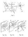
- a first embodiment of the method according to the present invention provides the generation of a longitudinal alternate magnetic field B having a direction substantially parallel to the feeding direction of the strip, that is the vertical direction, as illustrated in Fig. 2a .
- the heating action obtained is uniform and the heating area 5 corresponds with a substantially rectangular area at the zone of impact 12 of the gas jets.
- the heating area 5 advantageously covers the total width of the strip 1, edges included.
- the heating induced by the uniform longitudinal field B depends on the intensity and the distribution of the induced currents 6, which are function of the penetration depth of the current in the strip, depending on the magnetic induction frequency, and function of the thickness of the strip itself.
- the frequency of the generated magnetic induction is varied in a manner to obtain a predetermined ratio between thickness of the strip and depth of the penetration of the induced currents in the strip itself, ranging between 0,5 and 20.
- the intensity of the alternate magnetic field is comprised between 0,05 and 1 T in the air at the "wiping" zone, that is at the air knife action zone.
- This first embodiment of the method according to the invention can be realised by means of a device comprising, in a first variant, one or more coils or turns 7, wound around the strip 1 and supplied with alternate or pulsed current in order to create a longitudinal magnetic field B, alternate or pulsed, inside said coils or turns, as illustrated in Fig. 3 , or comprising, in a second variant, magnetic yokes provided with poles 8, 8', placed at each of the surfaces of major extension of the strip, having the same function, arranged according to the diagram in Fig. 4 .
- the generated magnetic flux moves, parallel to the strip feeding direction, from the upper poles 8 to the lower poles 8' of the respective magnetic yoke.
- nozzles 4 are provided placed in proximity of the coil 7, preferably at half-height of the winding, as illustrated in Fig. 3a .
- the turns of the coil 7 can also be arranged closer to the strip at the top, and gradually further away from the strip at the bottom, as shown in Fig. 3b , or alternatively they can be provided in a decreasing number along the vertical plane towards the melted coating material bath, that is from top to bottom as shown in Fig. 3c .
- the flare angle ⁇ of the coil 7 with respect to the vertical plane is between 0° and 60°.
- the second variant of the device illustrated in Fig. 4a , on the other hand, provides means for generating electromagnetic fields comprising two inductors, each one for example composed of one or more windings or coils-30 wound around a ferromagnetic core or yoke 31, substantially having a C shape, while the means for generating gas jets comprise, for each inductor, a support and supply structure for supporting and supplying nozzle 4, the structure comprising a gas feed manifold 32 and the same nozzles, placed in proximity of each surface 11 of major extension of the steel strip 1 in exit from the melted coating material bath.
- the ferromagnetic cores 31, having a substantially C shape, are lamination stack or compact type and produced in ferromagnetic or magneto-dielectric or ferritic material, while the coils 30 are positioned opposite one another on each side of the steel strip 1 and can be cooled with water.
- the control of the alternating magnetic field frequency is provided according to the type and quality of the coating to be removed.
- the support structure comprising the feed manifold 32 and the nozzles 4, is positioned inside the ferromagnetic cores 31, the superposition of the gas jets over the action zone of the induction heating is always guaranteed.
- the nozzles 4, positioned placed in proximity of the magnetic yoke poles 8, 8' of each ferromagnetic core 31, can be placed inside or outside the inductors.
- an alternate or pulsed current flows through the coils 30 with a phase shift angle between currents equal to 180° in a manner such there is only one longitudinal magnetic flux generated by the magnetic flux loops 33, 33' circulating on each inductor.
- All the variants of the first embodiment of the invention are characterised by a vertical distribution of the coils or of the terminal parts of the magnetic yokes, in proximity of the strip feeding plane, ranging between 10 ⁇ 100 mm in order to advantageously concentrate the heating along a strip zone that extends in longitudinal direction for 5 ⁇ 30 mm and that is at least partially superimposed over the zone most intensely cooled by the air knives, extending longitudinally for about 3 ⁇ 10 mm, thus reducing the necessary heating power, equal to approximately 1 ⁇ 50 kW for metre of strip width.
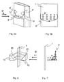
- a second embodiment of the method according to the invention instead, provides the generation of a non-uniform alternate magnetic field B' having a direction substantially perpendicular to the feeding direction of the strip, as shown in Fig. 5a .
- the heating action obtained is not uniform on the strip.
- the field B' has a gradient which causes a distribution of induced current represented by the curved line 6' such to heat both the edges and centre of the strip.
- the heating is localised in several heating areas:
- the gradient of the magnetic field B' can be obtained, in a first variant, by supplying a magnetic yoke in which the poles 10 in the- magnetic gap have a geometry that is similar to that illustrated in Fig. 6 , said poles being provided with a surface 20 inclined by an angle between 0° and 60° with respect to a vertical plane.
- This first variant illustrated in Fig. 6a , comprises two inductors, each one for example composed of one or more windings or coils 30 wound around a ferromagnetic core or yoke 31'.
- the two parts of the yoke 31', each one placed at a surface of major extension of the strip 1, are advantageously connected on the horizontal plane perpendicular to the sheet in order to close and maximise the magnetic flux.
- the means for generating gas jets comprise, for each inductor, a support and supply structure for supporting and supplying nozzles 4', the structure comprising a gas feed manifold 32' and placed outside the ferromagnetic yoke 31'.
- the nozzles 4' are placed immediately above said inductors and slightly inclined in a downward direction to ensure that the gas jet zone coincides with the action zone of magnetic field B'. This solution allows an easier access for nozzle cleaning since the upper part of the nozzles is unencumbered.
- the gradient of the magnetic field B' can be obtained, in a second alternative variant, by adopting a series or winding of non-uniformly distributed turns 7' of the type illustrated in Fig. 7 .
- the turns 7' arranged on one side only with respect to the feeding direction of the strip, are wound in a manner to define axes perpendicular to said direction and an internal surface inclined, with respect to a vertical plane, of an angle preferably comprised between 0° and 60°.
- a third embodiment of the method according to the invention is obtained by inverting the gradient of the non-uniform alternate magnetic field B", as illustrated in Fig. 8a .
- the gradient of the magnetic field B" causes a distribution of induced current represented by the curved line 6" such to heat both the edges and centre of the strip.
- the heating is localised in- several heating areas:
- the gradient of the magnetic field B" can be obtained, in a manner similar to that described above, in a first variant, by supplying a magnetic yoke whose poles 10 in the magnetic gap have a geometry similar to that illustrated in Fig. 9 , said poles being provided with a surface 20' inclined of an angle preferably comprised between 0° and 60° with respect to a vertical plane.
- This first variant illustrated in Fig. 9a , comprises two inductors, each one for example composed of one or more windings or coils 30' wound around a core or ferromagnetic yoke 31'.
- the two parts of the yoke 31', each one arranged at one surface of major extension of the strip 1, are advantageously connected on a horizontal plane perpendicular to the sheet in order to close and maximise the magnetic flux.
- the means for generating gas jets comprise, for each inductor, a support and supply structure for supporting and supplying nozzles 4', the structure comprising a gas feed manifold 32' and placed outside the ferromagnetic yoke 31'.
- the nozzles 4' are placed immediately above said inductors and slightly inclined in a downward direction to ensure that the gas jet zone coincides with the action zone of the magnetic field B". This solution allows an easier access for nozzle cleaning since the upper part of the nozzles is unencumbered.
- the gradient of the magnetic field B" can be realised, in a second alternative variant, by adopting a series or winding of non-uniformly distributed turns 7" of the type illustrated in Fig. 10 .
- the turns 7" arranged on one side only with respect to the feeding direction of the strip, are wound in a manner to define axes perpendicular to said direction and an internal surface inclined, with respect to a vertical plane, of an angle preferably comprised between 0° and 60°.
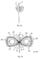
- a fourth embodiment of the method according to the invention is obtained by generating two non-uniform alternate magnetic fields B', B", having a direction perpendicular to the feeding direction of the strip and directions opposite to one another, that is by combining the second and third embodiments, as illustrated in the Figures from 11 a to 13.
- the distribution of the induced- currents 6', 6" on the surfaces 11 of the strip 1 are such to generate a heating at the centre of the surfaces 11 higher with respect to the edges. Therefore a central heating area 9'" wider than the central area 9 of the previous cases is provided; and second side heating areas 9', 9" are provided both above and below the area 9"'.
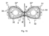
- the gradients of the magnetic fields B', B" can be realised by providing the combination, as illustrated in Figures 12 and 13 , of the magnetic yokes shown in Figures 6 and 9 , arranged symmetrically with respect to a horizontal plane, or the combination of the series or windings of the non uniformly distributed turns 7', 7" shown in Figures 7 and 10 , each winding being arranged to be placed at a respective side with respect to the feeding direction of the strip.
- this fourth embodiment of the method according to the invention can be realised by means of a device, such as that illustrated in Fig. 15 , totally identical to that already described above and illustrated in Fig. 4a .
- an alternate or pulsed current flows through the coils 30 with a phase shift angle between the currents equal to 0° in a manner such there is only one magnetic flux crossing the strip twice in opposite directions, said flux being generated by the magnetic flux loop 33" common to the two inductors.
- ferromagnetic yokes or cores with appropriately shaped poles allows to model the shape of the magnetic field.
- inclination of the poles with respect to the vertical direction, that is the feeding direction of the strip must be between 0° and 60° in order to be efficacious.
- the heating induced by field B' and/or B" depends on the intensity and the distribution of the induced currents 6' and/or 6", which are function of the intensity of the magnetic induction and its frequency. For example, for strips with a thickness ranging between 0,2 mm and 4 mm it is appropriate to work with frequencies ranging between 5 and 1000 Hz, preferably between 50 and 500 Hz.
- the intensity of the alternate magnetic field B', B" is, instead, comprised between 0,05 and 1 T, in the air.
- the induced heating is such that it contrasts the cooling- effect due to the gas jet or air knife action, whereby the heating areas 5, 9, 9', 9", 9"' must be provided underneath or at most at the zone of impact of said jets.
- the strip can be maintained in motion at a temperature that is substantially equal to that at the exit from the bath 2 until it reaches the impact zone of the jets, thus avoiding surface solidification of the zinc in proximity of the nozzles 4.
- the strip surface that could be subject to the risk of solidification is the part just below the nozzles 4, that is below the air jet impact zone, having a width approximately equal to that of the strip and having a height ranging between a few millimetres and 10 mm that corresponds with the pressure peak of the gas jet.
- the thermal power that can be removed from the strip in the gas jet impact zone, having a height equal to 1 ⁇ 10 mm, caused by the cooling of the gas jets, is variable between 1 and 50 kW according to the working conditions of the air knives.
- intensity and frequency of the magnetic field are regulated in order to provide the strip with a thermal power equivalent to that removed, thus being able to avoid premature solidification of the liquid coating before the excess coating is removed.
- the figures 14a to 14c show possible arrangements of the nozzles 4 with respect to the heating areas generated on the strip during feeding.
- the gas jet can be advantageously applied at or above the heating area 5. It must not be applied under this area 5 because the coating could have already attained the solid state when it reaches this area, therefore making the heating action, generated by the magnetic field B, ineffective.
- the induced heating will have a different effect according to whether the nozzles are placed in proximity of the central elliptical heating area or in proximity of the heating areas at the edges.
- the gas jet can be applied at or above the side heating areas 9'. It must not be applied under these areas 9' because the coating could have already attained the solid state when it reaches these heating areas, therefore making ineffective the heating action generated by the magnetic field B' at the edges. Therefore, in this case the nozzles 4 are preferably placed at or above the side heating areas 9', because, if they are placed at the central heating area 9, the thermal power supplied to heat the edges could become superfluous, as the coating at the edges could have already solidified by the time it reaches the areas 9'.
- the gas jetcan be applied at or above the central-heating area 9. It must not be applied under this area because the coating could have already attained the solid state when it reaches this area 9, therefore making ineffective the heating action generated by the magnetic field B" at the centre of the strip.
- the nozzles 4 are preferably placed at or above the central heating area 9, because, if they are placed at the side heating areas 9", the thermal power supplied to heat the central surface of the strip could become superfluous, as the coating in the centre could have already solidified by the time it reaches the central area 9.
- the gas jet generation occurs above the heating area or the heating areas furthest from the melted coating material bath. Therefore, the nozzles 4 are arranged above or at the coils or the magnetic poles that cause the localised heating.
- the localised heating of the strip coating performed by induction using electromagnetic fields, therefore allows to compensate the cooling effect of the air knives in the zone where they perform.
- the known travelling field "wiping" systems produce heating zones, or thermal action zones, which extend for a much greater longitudinal distance, longer than at least 100 mm, and consequently are less efficient.
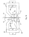
- the polar expansions or magnetic poles 8, 8' can be appropriately shaped to define the nozzles 4 adapted to generate gas jets, as in the example in Fig. 16 .
- the nozzles 4 are defined by the configuration of the polar expansions 8, 8' and have a passage orifice which, when seen in transversal section ( Fig . 16 ), has a shape tapering along the feeding direction of the strip.
- said passage orifice comprises two successive tapering stretches defining directions incident with one another.
- the distance between the magnetic yoke poles 8, 8', respectively the upper one and the lower one is comprised between 0,5 and 5 mm.
- each ferromagnetic core 31 and comprising the manifold 32 and possibly the nozzles 4 it can be provided at least one high electrical conductivity electromagnetic shield, placed between said structure and the core 31, that performs two functions:
- said electromagnetic shield placed inside the magnetic cores, can be shaped so that it forms the nozzle for the gas jets.
- the nozzles will be defined by the configuration of the electromagnetic shield or shields.
Landscapes
- Chemical & Material Sciences (AREA)
- Chemical Kinetics & Catalysis (AREA)
- Engineering & Computer Science (AREA)
- Materials Engineering (AREA)
- Mechanical Engineering (AREA)
- Metallurgy (AREA)
- Organic Chemistry (AREA)
- Coating With Molten Metal (AREA)
- Application Of Or Painting With Fluid Materials (AREA)
Claims (14)
- Verfahren zum Überprüfen der Dicke einer Beschichtung auf einem flachen Metallprodukt, wobei das Produkt eine Transportrichtung definiert, wenn es von einem Beschichtungsmaterial-Schmelzbad in einem kontinuierlichen Feuerverzinkungs-Ver-fahren austritt, worin darin bereitgestellt werden erste Mittel zum Erzeugen wenigstens eines alternierenden oder gepulsten einphasigen Magnetfeldes, und zweite Mittel zum Erzeugen von Gasströmen, die geeignet sind zur Herstellung von Gas strömen, die auf die Oberflächen einer Haupt-Erstreckung des Produktes gerichtet sind, wobei beide der Mittel in der Nähe der Oberflächen platziert sind, wobei das Verfahren die folgenden Abschnitte umfaßt, daß man(a) durch die ersten Mittel wenigstens ein alternierendes oder gepulstes einphasiges Magnetfeld (B, B', B") in der Nähe der Oberflächen des Produktes erzeugt, wobei das Magnetfeld eine Intensität zwischen 0,05 und 1 T in Luft und eine Frequenz zwischen 5 Hz und 500 kHz aufweist, eine Verteilung der Ströme (6, 6', 6") auf den Oberflächen induziert, und somit, abhängig von der Intensität und Frequenz des magnetischen Feldes und der Geometrie der Magnetflußröhre, eine Konzentration und Verteilung des Heizens auf den Oberflächen produziert, um wenigstens eine Heizfläche (9, 9', 9", 9'") auf den Oberflächen zu erzeugen;(b) eine Energie, die niedriger ist als 0,9 MW/m2, zu dem Produkt überführt, um eine Überhitzung des Produkts zu erreichen, die niedriger ist als 50 °C;(c) Gasströme durch die zweiten Mittel an der wenigstens einen Heizfläche erzeugt, um eine vorbestimmte einheitliche Beschichtungdicke entlang der gesamten Breite des Produktes zu erhalten.
- Verfahren nach Anspruch 1, worin das alternierende oder gepulste Magnetfeld (B) einheitlich ist und eine Richtung aufweist, die im Wesentlichen parallel zu der Transportrichtung des Produktes ist.
- Verfahren nach Anspruch 2, worin die Heizfläche (5), hergestellt an jeder der Oberflächen des Produktes, im Wesentlichen rechteckig ist und die gesamte Breite der Oberflächen bedeckt, einschließlich der Ecken.
- Verfahren nach Anspruch 3, worin das alternierende oder gepulste Magnetfeld eine Frequenz zwischen 0,5 und 500 kHz aufweist.
- Verfahren nach Anspruch 4, worin das alternierende oder gepulste Magnetfeld eine Frequenz zwischen 10 kHz und 300 kHz aufweist.
- Verfahren nach Anspruch 1, worin das alternierende oder gepulste Magnetfeld (B', B") nicht einheitlich ist und eine Richtung aufweist, die im Wesentlichen senkrecht zu der Transportrichtung des Produktes ist.
- Verfahren nach Anspruch 6, worin auf den Oberflächen einige Heizflächen erzeugt werden, einschließlich einer ersten zentralen Fläche (9, 9'"), die im Wesentlichen elliptisch ist, und zweiten Seitenflächen (9', 9"), die kleiner sind als die erste Fläche, in der Nähe der Kanten der Produkte, wobei die zweite Heizfläche erzeugt wird oberhalb (9') und/oder unterhalb (9") der ersten zentralen Heizfläche (9).
- Verfahren nach Anspruch 7, worin das alternierende oder gepulste Magnetfeld (B', B") eine Frequenz zwischen 5 und 1.000 Hz aufweist.
- Verfahren nach Anspruch 8, worin das alternierende oder gepulste Magnetfeld (B', B") eine Frequenz zwischen 50 Hz und 500 Hz aufweist.
- Verfahren nach Anspruch 4, 5, 8 oder 9, worin die thermische Energie, die an der Heizfläche oder den Heizflächen zugeführt wird, variabel ist zwischen 1 und 50 kW.
- Verfahren nach Anspruch 4, 5, 8 oder 9, worin die Erzeugung der Gasströme oberhalb der Heizfläche oder den Heizflächen geschieht, die am weitesten weg von dem Beschichtungsmaterial-Schmelzbad sind.
- Vorrichtung zum Überprüfen der Dicke einer Beschichtung auf einem flachen Metallprodukt (1) nach dem Verfahren von Anspruch 1, umfassend erste Mittel zum Erzeugen (4) wenigstens eines alternierenden oder gepulsten einphasigen Magnetfelds und zweite Mittel zum Erzeugen von Gasströmen, die geeignet sind zur Herstellung von Gasströmen, die auf die Oberflächen der Haupt-Erstreckung des Produktes gerichtet sind, wobei beide der Mittel zum Erzeugen der Gasströme und des magnetischen Feldes in der Nähe der Oberflächen platziert sind, wobei die ersten Mittel wenigstens eine magnetische Spule umfassen, die magnetischen Pole davon (10, 10') in dem Magnetspalt eine Oberfläche (20, 20') aufweisen, die, bezogen auf eine vertikale Ebene, in einem Winkel zwischen 0 ° und 60 ° geneigt ist, oder eine Wicklung von nicht einheitlich verteilten Windungen (7', 7") umfassen, um eine innere Oberfäche zu definieren, die, bezogen auf die vertikale Ebene, in einem Winkel zwischen 0 ° und 60 ° geneigt ist.
- Vorrichtung nach Anspruch 12, worin zwei magnetische Spulen bereitgestellt werden, die jeweils mit ersten Polen (10) und zweiten Polen (10') versehen sind, die an beiden Seiten angeordnet sind, bezogen auf die Transportrichtung des flachen Metallproduktes (1) oder zwei magnetische Wicklungen von nicht einheitlich verteilten Windungen (7', 7") bereitgestellt werden, die an beiden Seiten angeordnet sind, bezogen auf die Transportrichtung des Streifens, um zwei alternierende oder gepulste Magnetfelder (B', B") zu erzeugen, die gegensätzliche Richtungen aufweisen.
- Vorrichtung nach Anspruch 13, worin die zwei Magnetspulen einen gemeinsamen Magnetfluss aufweisen, der das flache Metallprodukt zweimal in gegensätzlichen Richtungen kreuzt.
Applications Claiming Priority (2)
| Application Number | Priority Date | Filing Date | Title |
|---|---|---|---|
| ITMI20071164 ITMI20071164A1 (it) | 2007-06-08 | 2007-06-08 | Metodo e dispositivo per il controllo dello spessore di rivestimento di un prodotto metallico piano |
| PCT/IB2008/001471 WO2008149217A2 (en) | 2007-06-08 | 2008-06-09 | Method and device for controlling the thickness of a coating on a flat metal product |
Publications (2)
| Publication Number | Publication Date |
|---|---|
| EP2165000A2 EP2165000A2 (de) | 2010-03-24 |
| EP2165000B1 true EP2165000B1 (de) | 2014-07-30 |
Family
ID=38863069
Family Applications (1)
| Application Number | Title | Priority Date | Filing Date |
|---|---|---|---|
| EP08762807.9A Not-in-force EP2165000B1 (de) | 2007-06-08 | 2008-06-09 | Verfahren und vorrichtung zur steuerung der dicke einer beschichtung auf einem flachen metallprodukt |
Country Status (4)
| Country | Link |
|---|---|
| EP (1) | EP2165000B1 (de) |
| CN (1) | CN101720360B (de) |
| IT (1) | ITMI20071164A1 (de) |
| WO (1) | WO2008149217A2 (de) |
Families Citing this family (4)
| Publication number | Priority date | Publication date | Assignee | Title |
|---|---|---|---|---|
| ITMI20111131A1 (it) * | 2011-06-21 | 2012-12-22 | Danieli Off Mecc | Dispositivo di generazione di getto di gas per processi di rivestimento di nastri metallici |
| IT202000020626A1 (it) | 2020-08-28 | 2022-02-28 | Matricar Di Matricardi Luciano | Dispositivo a gabbia di sicurezza e veicolo comprendente tale dispositivo |
| CN113118043B (zh) * | 2021-03-10 | 2023-05-02 | 华奈克(武汉)汽车部件有限公司 | 一种点火线圈铁芯的表面涂层厚度检测装置 |
| CN117187727B (zh) * | 2023-09-11 | 2025-09-05 | 江苏省沙钢钢铁研究院有限公司 | 一种板材边部镀层厚度控制装置及方法 |
Citations (1)
| Publication number | Priority date | Publication date | Assignee | Title |
|---|---|---|---|---|
| US4273800A (en) * | 1977-11-24 | 1981-06-16 | John Lysaght (Australia) Limited | Coating mass control using magnetic field |
Family Cites Families (8)
| Publication number | Priority date | Publication date | Assignee | Title |
|---|---|---|---|---|
| SE341651B (de) * | 1969-05-19 | 1972-01-10 | Asea Ab | |
| KR950000007B1 (ko) * | 1991-06-25 | 1995-01-07 | 니홍고오깡가부시끼가이샤 | 용융도금의 강대상에 도포중량을 제어하기 위한 방법 |
| JP2602757B2 (ja) * | 1992-05-29 | 1997-04-23 | 新日本製鐵株式会社 | 薄目付け連続溶融メッキ法 |
| BE1011059A6 (fr) * | 1997-03-25 | 1999-04-06 | Centre Rech Metallurgique | Procede de revetement d'une bande d'acier par galvanisation au trempe. |
| DE10255994A1 (de) * | 2002-11-30 | 2004-06-09 | Sms Demag Ag | Verfahren und Vorrichtung zur Schmelztauchbeschichtung eines Metallstranges |
| SE527507C2 (sv) * | 2004-07-13 | 2006-03-28 | Abb Ab | En anordning och ett förfarande för stabilisering av ett metalliskt föremål samt en användning av anordningen |
| SE528663C2 (sv) * | 2005-06-03 | 2007-01-16 | Abb Ab | En anordning och ett förfarande för att belägga ett långsträckt metalliskt element med ett skikt av metall |
| SE529060C2 (sv) * | 2005-06-30 | 2007-04-24 | Abb Ab | Anordning samt förfarande för tjockleksstyrning |
-
2007
- 2007-06-08 IT ITMI20071164 patent/ITMI20071164A1/it unknown
-
2008
- 2008-06-09 EP EP08762807.9A patent/EP2165000B1/de not_active Not-in-force
- 2008-06-09 CN CN2008800192979A patent/CN101720360B/zh not_active Expired - Fee Related
- 2008-06-09 WO PCT/IB2008/001471 patent/WO2008149217A2/en not_active Ceased
Patent Citations (1)
| Publication number | Priority date | Publication date | Assignee | Title |
|---|---|---|---|---|
| US4273800A (en) * | 1977-11-24 | 1981-06-16 | John Lysaght (Australia) Limited | Coating mass control using magnetic field |
Also Published As
| Publication number | Publication date |
|---|---|
| WO2008149217A3 (en) | 2009-01-29 |
| CN101720360A (zh) | 2010-06-02 |
| CN101720360B (zh) | 2011-12-28 |
| EP2165000A2 (de) | 2010-03-24 |
| ITMI20071164A1 (it) | 2008-12-09 |
| WO2008149217A2 (en) | 2008-12-11 |
Similar Documents
| Publication | Publication Date | Title |
|---|---|---|
| JP6875530B2 (ja) | コンパクトな連続焼き鈍し溶体化熱処理 | |
| KR101372765B1 (ko) | 전자기 와이핑 장치와 이를 포함하는 도금강판 와이핑 장치 | |
| US9462641B2 (en) | Transverse flux strip heating with DC edge saturation | |
| EP2165000B1 (de) | Verfahren und vorrichtung zur steuerung der dicke einer beschichtung auf einem flachen metallprodukt | |
| EP2167697B1 (de) | Verfahren und vorrichtung zur steuerung der dicke einer beschichtung auf einem flachen metallprodukt | |
| RU2482213C2 (ru) | Способ и устройство отжима жидкого металла покрытия на выходе бака для нанесения металлического покрытия погружением | |
| CN101720361B (zh) | 用于控制平的金属制品上的涂层厚度的方法和装置 | |
| JP2602757B2 (ja) | 薄目付け連続溶融メッキ法 | |
| JP5526677B2 (ja) | 連続溶融金属めっきの付着量制御装置 | |
| KR101051325B1 (ko) | 금속판재의 주석도금 공정처리용 리플로우 장비 및 방법 | |
| JP2006131983A (ja) | 連続溶融金属めっきの付着量制御方法および付着量制御装置 | |
| JP2619474B2 (ja) | 高速薄目付溶融メッキ法 | |
| JP3498430B2 (ja) | 溶融金属めっき鋼板の製造装置 | |
| JP4867453B2 (ja) | 連続溶融金属めっきの付着量制御装置 | |
| Chen et al. | Design and Simulation of Three-Phase Electromagnetic Wiping Device for Steel Strips Hot-Dip Galvanizing | |
| JPH0721567Y2 (ja) | 溶融メッキ装置 | |
| JPWO2018155245A1 (ja) | 連続溶融金属めっき処理装置及び該装置を用いた溶融金属めっき処理方法 | |
| JP2530909Y2 (ja) | 溶融めっきのエッジオーバーコート防止装置 | |
| JPS62205258A (ja) | 溶融金属めつき装置 | |
| JPS62205259A (ja) | 溶融金属めつき装置 |
Legal Events
| Date | Code | Title | Description |
|---|---|---|---|
| PUAI | Public reference made under article 153(3) epc to a published international application that has entered the european phase |
Free format text: ORIGINAL CODE: 0009012 |
|
| 17P | Request for examination filed |
Effective date: 20100108 |
|
| AK | Designated contracting states |
Kind code of ref document: A2 Designated state(s): AT BE BG CH CY CZ DE DK EE ES FI FR GB GR HR HU IE IS IT LI LT LU LV MC MT NL NO PL PT RO SE SI SK TR |
|
| AX | Request for extension of the european patent |
Extension state: AL BA MK RS |
|
| RIN1 | Information on inventor provided before grant (corrected) |
Inventor name: GUASTINI, FABIO Inventor name: CODUTTI, ANDREA Inventor name: POLONI, ALFREDO Inventor name: PAVLICEVIC, MILORAD |
|
| 17Q | First examination report despatched |
Effective date: 20101109 |
|
| DAX | Request for extension of the european patent (deleted) | ||
| GRAP | Despatch of communication of intention to grant a patent |
Free format text: ORIGINAL CODE: EPIDOSNIGR1 |
|
| INTG | Intention to grant announced |
Effective date: 20140122 |
|
| GRAS | Grant fee paid |
Free format text: ORIGINAL CODE: EPIDOSNIGR3 |
|
| GRAA | (expected) grant |
Free format text: ORIGINAL CODE: 0009210 |
|
| AK | Designated contracting states |
Kind code of ref document: B1 Designated state(s): AT BE BG CH CY CZ DE DK EE ES FI FR GB GR HR HU IE IS IT LI LT LU LV MC MT NL NO PL PT RO SE SI SK TR |
|
| REG | Reference to a national code |
Ref country code: GB Ref legal event code: FG4D |
|
| REG | Reference to a national code |
Ref country code: CH Ref legal event code: EP |
|
| REG | Reference to a national code |
Ref country code: AT Ref legal event code: REF Ref document number: 680045 Country of ref document: AT Kind code of ref document: T Effective date: 20140815 |
|
| REG | Reference to a national code |
Ref country code: IE Ref legal event code: FG4D |
|
| REG | Reference to a national code |
Ref country code: DE Ref legal event code: R096 Ref document number: 602008033593 Country of ref document: DE Effective date: 20140911 |
|
| REG | Reference to a national code |
Ref country code: AT Ref legal event code: MK05 Ref document number: 680045 Country of ref document: AT Kind code of ref document: T Effective date: 20140730 |
|
| REG | Reference to a national code |
Ref country code: NL Ref legal event code: VDEP Effective date: 20140730 |
|
| REG | Reference to a national code |
Ref country code: LT Ref legal event code: MG4D |
|
| PG25 | Lapsed in a contracting state [announced via postgrant information from national office to epo] |
Ref country code: BG Free format text: LAPSE BECAUSE OF FAILURE TO SUBMIT A TRANSLATION OF THE DESCRIPTION OR TO PAY THE FEE WITHIN THE PRESCRIBED TIME-LIMIT Effective date: 20141030 Ref country code: SE Free format text: LAPSE BECAUSE OF FAILURE TO SUBMIT A TRANSLATION OF THE DESCRIPTION OR TO PAY THE FEE WITHIN THE PRESCRIBED TIME-LIMIT Effective date: 20140730 Ref country code: ES Free format text: LAPSE BECAUSE OF FAILURE TO SUBMIT A TRANSLATION OF THE DESCRIPTION OR TO PAY THE FEE WITHIN THE PRESCRIBED TIME-LIMIT Effective date: 20140730 Ref country code: FI Free format text: LAPSE BECAUSE OF FAILURE TO SUBMIT A TRANSLATION OF THE DESCRIPTION OR TO PAY THE FEE WITHIN THE PRESCRIBED TIME-LIMIT Effective date: 20140730 Ref country code: NO Free format text: LAPSE BECAUSE OF FAILURE TO SUBMIT A TRANSLATION OF THE DESCRIPTION OR TO PAY THE FEE WITHIN THE PRESCRIBED TIME-LIMIT Effective date: 20141030 Ref country code: PT Free format text: LAPSE BECAUSE OF FAILURE TO SUBMIT A TRANSLATION OF THE DESCRIPTION OR TO PAY THE FEE WITHIN THE PRESCRIBED TIME-LIMIT Effective date: 20141202 Ref country code: LT Free format text: LAPSE BECAUSE OF FAILURE TO SUBMIT A TRANSLATION OF THE DESCRIPTION OR TO PAY THE FEE WITHIN THE PRESCRIBED TIME-LIMIT Effective date: 20140730 Ref country code: GR Free format text: LAPSE BECAUSE OF FAILURE TO SUBMIT A TRANSLATION OF THE DESCRIPTION OR TO PAY THE FEE WITHIN THE PRESCRIBED TIME-LIMIT Effective date: 20141031 |
|
| PG25 | Lapsed in a contracting state [announced via postgrant information from national office to epo] |
Ref country code: PL Free format text: LAPSE BECAUSE OF FAILURE TO SUBMIT A TRANSLATION OF THE DESCRIPTION OR TO PAY THE FEE WITHIN THE PRESCRIBED TIME-LIMIT Effective date: 20140730 Ref country code: AT Free format text: LAPSE BECAUSE OF FAILURE TO SUBMIT A TRANSLATION OF THE DESCRIPTION OR TO PAY THE FEE WITHIN THE PRESCRIBED TIME-LIMIT Effective date: 20140730 Ref country code: LV Free format text: LAPSE BECAUSE OF FAILURE TO SUBMIT A TRANSLATION OF THE DESCRIPTION OR TO PAY THE FEE WITHIN THE PRESCRIBED TIME-LIMIT Effective date: 20140730 Ref country code: CY Free format text: LAPSE BECAUSE OF FAILURE TO SUBMIT A TRANSLATION OF THE DESCRIPTION OR TO PAY THE FEE WITHIN THE PRESCRIBED TIME-LIMIT Effective date: 20140730 Ref country code: NL Free format text: LAPSE BECAUSE OF FAILURE TO SUBMIT A TRANSLATION OF THE DESCRIPTION OR TO PAY THE FEE WITHIN THE PRESCRIBED TIME-LIMIT Effective date: 20140730 Ref country code: HR Free format text: LAPSE BECAUSE OF FAILURE TO SUBMIT A TRANSLATION OF THE DESCRIPTION OR TO PAY THE FEE WITHIN THE PRESCRIBED TIME-LIMIT Effective date: 20140730 Ref country code: IS Free format text: LAPSE BECAUSE OF FAILURE TO SUBMIT A TRANSLATION OF THE DESCRIPTION OR TO PAY THE FEE WITHIN THE PRESCRIBED TIME-LIMIT Effective date: 20141130 |
|
| PG25 | Lapsed in a contracting state [announced via postgrant information from national office to epo] |
Ref country code: SK Free format text: LAPSE BECAUSE OF FAILURE TO SUBMIT A TRANSLATION OF THE DESCRIPTION OR TO PAY THE FEE WITHIN THE PRESCRIBED TIME-LIMIT Effective date: 20140730 Ref country code: DK Free format text: LAPSE BECAUSE OF FAILURE TO SUBMIT A TRANSLATION OF THE DESCRIPTION OR TO PAY THE FEE WITHIN THE PRESCRIBED TIME-LIMIT Effective date: 20140730 Ref country code: CZ Free format text: LAPSE BECAUSE OF FAILURE TO SUBMIT A TRANSLATION OF THE DESCRIPTION OR TO PAY THE FEE WITHIN THE PRESCRIBED TIME-LIMIT Effective date: 20140730 Ref country code: RO Free format text: LAPSE BECAUSE OF FAILURE TO SUBMIT A TRANSLATION OF THE DESCRIPTION OR TO PAY THE FEE WITHIN THE PRESCRIBED TIME-LIMIT Effective date: 20140730 Ref country code: EE Free format text: LAPSE BECAUSE OF FAILURE TO SUBMIT A TRANSLATION OF THE DESCRIPTION OR TO PAY THE FEE WITHIN THE PRESCRIBED TIME-LIMIT Effective date: 20140730 |
|
| REG | Reference to a national code |
Ref country code: DE Ref legal event code: R097 Ref document number: 602008033593 Country of ref document: DE |
|
| PLBE | No opposition filed within time limit |
Free format text: ORIGINAL CODE: 0009261 |
|
| STAA | Information on the status of an ep patent application or granted ep patent |
Free format text: STATUS: NO OPPOSITION FILED WITHIN TIME LIMIT |
|
| 26N | No opposition filed |
Effective date: 20150504 |
|
| PG25 | Lapsed in a contracting state [announced via postgrant information from national office to epo] |
Ref country code: SI Free format text: LAPSE BECAUSE OF FAILURE TO SUBMIT A TRANSLATION OF THE DESCRIPTION OR TO PAY THE FEE WITHIN THE PRESCRIBED TIME-LIMIT Effective date: 20140730 |
|
| PG25 | Lapsed in a contracting state [announced via postgrant information from national office to epo] |
Ref country code: MC Free format text: LAPSE BECAUSE OF FAILURE TO SUBMIT A TRANSLATION OF THE DESCRIPTION OR TO PAY THE FEE WITHIN THE PRESCRIBED TIME-LIMIT Effective date: 20140730 |
|
| REG | Reference to a national code |
Ref country code: CH Ref legal event code: PL |
|
| GBPC | Gb: european patent ceased through non-payment of renewal fee |
Effective date: 20150609 |
|
| PG25 | Lapsed in a contracting state [announced via postgrant information from national office to epo] |
Ref country code: LU Free format text: LAPSE BECAUSE OF FAILURE TO SUBMIT A TRANSLATION OF THE DESCRIPTION OR TO PAY THE FEE WITHIN THE PRESCRIBED TIME-LIMIT Effective date: 20150609 |
|
| REG | Reference to a national code |
Ref country code: IE Ref legal event code: MM4A |
|
| PG25 | Lapsed in a contracting state [announced via postgrant information from national office to epo] |
Ref country code: GB Free format text: LAPSE BECAUSE OF NON-PAYMENT OF DUE FEES Effective date: 20150609 Ref country code: IE Free format text: LAPSE BECAUSE OF NON-PAYMENT OF DUE FEES Effective date: 20150609 Ref country code: CH Free format text: LAPSE BECAUSE OF NON-PAYMENT OF DUE FEES Effective date: 20150630 Ref country code: LI Free format text: LAPSE BECAUSE OF NON-PAYMENT OF DUE FEES Effective date: 20150630 |
|
| REG | Reference to a national code |
Ref country code: FR Ref legal event code: PLFP Year of fee payment: 9 |
|
| PG25 | Lapsed in a contracting state [announced via postgrant information from national office to epo] |
Ref country code: BE Free format text: LAPSE BECAUSE OF FAILURE TO SUBMIT A TRANSLATION OF THE DESCRIPTION OR TO PAY THE FEE WITHIN THE PRESCRIBED TIME-LIMIT Effective date: 20140730 |
|
| PG25 | Lapsed in a contracting state [announced via postgrant information from national office to epo] |
Ref country code: MT Free format text: LAPSE BECAUSE OF FAILURE TO SUBMIT A TRANSLATION OF THE DESCRIPTION OR TO PAY THE FEE WITHIN THE PRESCRIBED TIME-LIMIT Effective date: 20140730 |
|
| REG | Reference to a national code |
Ref country code: FR Ref legal event code: PLFP Year of fee payment: 10 |
|
| PG25 | Lapsed in a contracting state [announced via postgrant information from national office to epo] |
Ref country code: HU Free format text: LAPSE BECAUSE OF FAILURE TO SUBMIT A TRANSLATION OF THE DESCRIPTION OR TO PAY THE FEE WITHIN THE PRESCRIBED TIME-LIMIT; INVALID AB INITIO Effective date: 20080609 |
|
| PG25 | Lapsed in a contracting state [announced via postgrant information from national office to epo] |
Ref country code: TR Free format text: LAPSE BECAUSE OF FAILURE TO SUBMIT A TRANSLATION OF THE DESCRIPTION OR TO PAY THE FEE WITHIN THE PRESCRIBED TIME-LIMIT Effective date: 20140730 |
|
| REG | Reference to a national code |
Ref country code: FR Ref legal event code: PLFP Year of fee payment: 11 |
|
| PGFP | Annual fee paid to national office [announced via postgrant information from national office to epo] |
Ref country code: FR Payment date: 20200520 Year of fee payment: 13 Ref country code: DE Payment date: 20200519 Year of fee payment: 13 |
|
| PGFP | Annual fee paid to national office [announced via postgrant information from national office to epo] |
Ref country code: IT Payment date: 20200519 Year of fee payment: 13 |
|
| REG | Reference to a national code |
Ref country code: DE Ref legal event code: R119 Ref document number: 602008033593 Country of ref document: DE |
|
| PG25 | Lapsed in a contracting state [announced via postgrant information from national office to epo] |
Ref country code: DE Free format text: LAPSE BECAUSE OF NON-PAYMENT OF DUE FEES Effective date: 20220101 |
|
| PG25 | Lapsed in a contracting state [announced via postgrant information from national office to epo] |
Ref country code: FR Free format text: LAPSE BECAUSE OF NON-PAYMENT OF DUE FEES Effective date: 20210630 |
|
| PG25 | Lapsed in a contracting state [announced via postgrant information from national office to epo] |
Ref country code: IT Free format text: LAPSE BECAUSE OF NON-PAYMENT OF DUE FEES Effective date: 20210609 |