EP2165585B1 - Kühlsystem und benutzungsverfahren - Google Patents
Kühlsystem und benutzungsverfahren Download PDFInfo
- Publication number
- EP2165585B1 EP2165585B1 EP07869465A EP07869465A EP2165585B1 EP 2165585 B1 EP2165585 B1 EP 2165585B1 EP 07869465 A EP07869465 A EP 07869465A EP 07869465 A EP07869465 A EP 07869465A EP 2165585 B1 EP2165585 B1 EP 2165585B1
- Authority
- EP
- European Patent Office
- Prior art keywords
- electronic device
- line
- breaker box
- quick connector
- interlock
- Prior art date
- Legal status (The legal status is an assumption and is not a legal conclusion. Google has not performed a legal analysis and makes no representation as to the accuracy of the status listed.)
- Active
Links
Images



Classifications
-
- H—ELECTRICITY
- H05—ELECTRIC TECHNIQUES NOT OTHERWISE PROVIDED FOR
- H05K—PRINTED CIRCUITS; CASINGS OR CONSTRUCTIONAL DETAILS OF ELECTRIC APPARATUS; MANUFACTURE OF ASSEMBLAGES OF ELECTRICAL COMPONENTS
- H05K7/00—Constructional details common to different types of electric apparatus
- H05K7/20—Modifications to facilitate cooling, ventilating, or heating
- H05K7/20709—Modifications to facilitate cooling, ventilating, or heating for server racks or cabinets; for data centers, e.g. 19-inch computer racks
- H05K7/20763—Liquid cooling without phase change
- H05K7/2079—Liquid cooling without phase change within rooms for removing heat from cabinets
Definitions
- This disclosure relates generally to cooling systems, and more particularly to use of liquid coolants with respect to electronic components.
- a need exists for a connector that overcomes the limitations normally encountered in circulating coolant in a flexibly configured plumbing system by addressing each of the performance bottlenecks or limitations of existing designs.
- a need also exists to provide a method of pumping coolant at the server, on-board, or chip level via a simple connection means.
- the present invention includes a coordinated system to allow quick coolant connections at the electronic device in a very simple, user-friendly manner and offer the use of a breaker box system to provide liquid coolant to at least one server. It removes the major barriers to using two-phase coolant as the cooling medium.
- the present invention relates to a system for cooling at least one electronic device with a liquid coolant, wherein each electronic device has a wireless identifier
- the system comprising: a pumper module; a breaker box; a supply line connected to the pumper module and the breaker box system; a return line connected to the pumper module and the breaker box system; a quick connector; a data reader capable of reading the wireless identifier; a connector line connected to the breaker box system and the quick connector; and/or a software monitoring and control system.
- the system may also include a filtration/purification system in connection with the pumper module and the breaker box, a connection interlock; and an interlock engager/disengager.
- the quick connector may further comprise status lights, and/or a pneumatic interlock, wherein the connector line comprises metallic layers and polymer layers.
- RFID is a preferred embodiment and an active transmitter with communications from the server, or could be other passive ID, such as barcode or matrix bar code, or similar identification.
- the liquid coolant is preferably a refrigerant.
- the breaker box may further comprise a pump and a reservoir.
- a quick connector for use in a system for cooling at least one electronic device having a wireless identifier with a liquid coolant comprising: a data reader capable of reading the wireless identifier of the server; a connection interlock; and an interlock engager/disengager.
- the quick connector may further comprise status lights, a connector supply line; a connector return line; wherein the pneumatic interlock is capable of restricting connection or disconnection; and/or an interlock confirm.
- the liquid coolant is preferably a refrigerant.
- a breaker box for use in cooling at least one electronic device with a liquid coolant comprising: at least one pump; at least one reservoir; a supply line connected to the breaker box system; a return line connected to the breaker box system; a water line; and a heat exchanger in thermal communication with the water line, the supply line, and the return line.
- each pump, each reservoir, and the heat exchanger are located within the breaker box and/or the liquid coolant is water.
- a method of cooling at least one electronic device wherein the electronic device has a receptacle, an electronic device supply line receiver, and an electronic device return line receiver, and wherein the receptacle has a wireless identifier, which comprises the steps of: (a) connecting a quick connector to the receptacle, wherein the quick connector comprises a data reader capable of reading the wireless identifier, a supply line, and a return line; (b) reading data from the wireless identifier; (c) connecting the supply line to the electronic device supply line receiver; and (d) connecting the return line to the electronic device return line receiver.
- the method may also include feeding refrigerant through at least one line.
- a method of cooling at least one electronic device using a liquid coolant which comprises the steps of: (a) routing a supply line, a return line, and a water coolant line into a breaker box; (b) connecting the liquid coolant line to the server; (c) pumping water to and from the electronic device in the water coolant line with a pump; and (d) exchanging heat from the liquid coolant line to the return line using a heat exchanger.
- the method may also include maintaining a supply of liquid in a reservoir.
- the pump, the reservoir, and the heat exchanger are located within the breaker box, the liquid coolant is water, and/or the method uses the quick connector.
- US 6714412 relates to a scalable coolant conditioning unit (SCCU) is designed to accommodate removable modular pumping units (MPU's).
- the MPU's may comprise one or a plurality of pump/pump motor combinations.
- the MPU's are connected to coolant supply and discharge mechanisms by an insertion facilitation mechanism comprising an automatic coupling assembly and an isolation valve mechanism and are placed into and removed from the SCCU body with the aid of a seating mechanism.
- MPU's are added to an operating SCCU as needed to support increased heat loads of electronics frames.
- a plate heat exchanger is physically integrated within the expansion tank, reducing volumetric requirements for the SCCU and is sized to accommodate the maximum heat load.
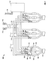
- Figure 1 is a diagram of an embodiment of the overall system.
- Figure 2 is a close up diagram of an embodiment of the electronic device receptacle.
- Figure 3 is a cross sectional side view of an embodiment of the quick connector.
- Figure 4 is a perspective cut away view of an embodiment of a line.
- Figure 5 is a cross sectional longitudinal view of an embodiment of the supply line and the return line.
- Figure 6 is a cross sectional longitudinal view of an embodiment of the supply line and the return line.
- Figure 7 is a diagram of an embodiment of the breaker box.
- Figure 8 is a diagram of an embodiment of the clean/purge system.
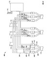
- Figure 9 is a diagram of an embodiment of the breaker box.
- the system described herein preferably includes a pumped coolant module, a filtration/purification system, dry nitrogen or similar compressed gas, a vacuum systems a breaker box system, a quick connector system, flexible coolant lines, and a software monitoring and control system.
- a plurality of electronic devices 100 is shown.
- the electronic devices are servers, but those skilled in the art will recognize that any electronic devices, modules, or assemblies are considered to be within the scope of the invention.
- Each electronic device 100 is cooled in part by a circulation of coolant that enters the electronic device 100 via an electronic device supply line and leaves the electronic device 100 via an electronic device return line contained within the quick connector 106.
- the quick connector 106 is connected to the breaker box 108 via a connector line 110.
- the breaker box 108 is also connected to a supply line 112, a return line 114, a clean/purge line 116, and a data/power line 118.
- the supply line 112, return line 114, and data/power line 118 are directly connected to a coolant pumper module 120.
- the clean/purge line 116 is also indirectly connected to the coolant pumper module 120, but a few components shown in greater detail in FIG. 8 provide greater detail about the clean/purge system.
- a plurality of electronic devices 100 may be connected by a plurality of corresponding quick connectors 106 via a plurality of breaker boxes 108 and via at least one coolant pumper module 120.
- This arrangement allows for the cooling of racks 102 of electronic devices 100.
- the quick connector 106 further enables this arrangement to be simpler with less bulky connections.
- each electronic device 100 has a receptacle 200 as shown.
- the receptacle 200 as shown includes a wireless identifier 202, preferably a radio frequency identification (“RFID”) identifier, an interlocking pin 204, an electronic device supply line receiver 206, and an electronic device return line receiver 208.
- RFID radio frequency identification
- RFID is a preferred embodiment and an active transmitter with communications from the server, or could be other passive ID, such as barcode or matrix bar code, or similar identification.
- the quick connector 106 is shown in greater detail in FIG. 3 .
- the quick connector 106 has a data reader 300, a connection interlock 302, an electronic device supply line coupling 304, an electronic device return line coupling 306.
- the data reader 300 is capable of reading the wireless identifier 202. It preferred that the data reader 300 is capable of reading the wireless identifier 202 before, during, or after quick connector 106 is engaged with the receptacle 200.
- the interlock pin 204 is enclosed within the connection interlock 302 when the quick connector 106 is engaged with the receptacle 200.
- the interlock pin 204 is but one embodiment capable of affecting the connection and that variations of this element are considered to be within the scope of the invention.
- the interlock pin 204 may disallow a connection if there is some incompatibility, such as capacity, connector style, unit identification issues, or similar incompatibility and to disallow a disconnection if the lines are charged with refrigerant.
- the electronic device supply line coupling 304 and the electronic device return line coupling 306 interface with the electronic device supply line receiver 206 and the electronic device return line receiver 208, respectively, when the quick connector 106 is engaged with the receptacle 200.
- the electronic device supply line coupling 304 is connected to a connector supply line 308, which passes through the quick connector 106 into the connector line 110.
- the electronic device return line coupling 306 is connected to a connector return line 310, which passes through the quick connector 106 into the connector line 110.
- a connector data line 312 is connected to the data reader 300 and passes through the quick connector 106 into the connector line 110 also.
- data reader 300 may be an interface for at least one signal from the server, with the actual reader located at the breaker box or at the pumper or at some master control.
- the connector line 110 also contains a power line, which is connected to several additional components within the quick connector, in addition to the connector data line 312.
- the additional components include an interlock confirm 314, an interlock engager/disengager 316, and status lights 318.
- the interlock engager/disengager 316 may be electronic, pneumatic, hydraulic, magnetic, mechanical, or any similar means.
- a pneumatic effect ensures the pneumatic interlock 320 can not be released if the lines contain pressurized fluid or is otherwise regulated by the interlock engager/disengager 316.
- the connector 106 cannot be connected or disconnected if the lines are pressurized or if the connection/disconnection is not permitted as controlled by software or hardware logic controlling the action of the interlock engager/disengager 316.
- the full insertion of the interlock pin 204 into the connection interlock 302 will trigger the interlock confirm 314. This action may be coupled with visual indications from the status lights 318, wherein a color or display pattern or sequence may allow the user to determine the connection status of the quick connector 106.
- an electro-mechanical solenoid lock or similar device is disengaged to allow connection.
- the RFID information is sent to the coolant pumper module 120 and the breaker box 108 for further processing. Electrical and/or mechanical interlocks are maintained until it is safe to disconnect the quick connector.
- FIG. 4 Examples of the lines that may be used for the supply or return lines are shown in greater detail in FIGs. 4-6 .
- a polymer is too porous with respect to coolant and moisture, although it has the sufficient inherent strength and flexibility for use as a coolant line.
- the porous nature of the polymer layers is affected by adding a coating of metallization film by vacuum vapor deposition or similar techniques.
- the metal film seals the polymer's pores, as well as adding hoop strength to the tubing.
- FIGs. 5 and 6 show two different configurations of the connection line 110.
- the supply line 500 is located within the return line 502.
- FIG. 5 allows the metallization layer to be omitted for the supply line, because any small porosity will allow leakage from the supply line only into the return line, which is then collected with ordinary flow in the return line. Further, it allows the supply line to be thinner and more flexible, because the supply line only then has to support the difference in pressure between the supply and return lines, rather than from the supply to ambient pressure, which may be significantly greater.
- the supply line 600 is adjacent to the return line 602.
- each connector line 110 is connected to the breaker box 108 as shown. Additionally, the supply line 112, the return line 114, the clean/purge line 116, and the data/power line 118 are connected to the breaker box 108. At the breaker box 108, each of these lines may be connected with standard connectors 700, 702, and 704 as shown for the leftmost connector line 110. Those skilled in the art will recognize that a plurality of connector lines, such as the two additional connector lines shown in the Figure, may be included within each breaker box.
- solenoid valves 706, 708, and 710 or standard non-spill quick disconnects may be installed on these lines as shown. Ordinarily, the connection of the lines to the breaker box 108 remains in place and is connected before the electronic device 100 is connected.
- the breaker box 108 is akin to an electrical breaker box with breakers.
- the breaker box 108 contains preferably electronically controlled valves that prevent coolant from flowing to the electronic device 100 until the lines have been properly prepared.
- the data line/power lines 118 provides a signal to the control computer or a relay communication device 712 at the breaker box 108 that a valid connection has been made.
- the filtration/purification system 800 shown in FIG. 8 is responsible for continuous filtering of moisture from the coolant supply, as well as removal of non-condensable gases, and any particulates.
- the coolant pumper module 120 is connected to the filtration/purification system 800.
- the non-condensable gases are removed from the filter system the by a vacuum system 802 connected to the filtration/purification system 800 and also connected to the breaker box 108.
- the vacuum either purges the residual gas to the atmosphere via a vent 804 or is pumped to a purge/storage tank 806 that is periodically emptied/changed with its contents disposed of according to local regulations.
- the filtration/purification system 800 works by membrane separation, pressure-swing or temperature-swing adsorption/desorption processes, or similar methods. For example, this system 800 may be affected by how well the vacuum 802 is able to operate. Moreover, the amount of residual moisture/gas that is left in the lines may affect the system 800. Other factors that may affect the usage of the system 800 include how often connections/disconnections are made and how much residual contaminant the coolant pumper module can tolerate without issue.
- the vacuum system 802 coordinates to purge the lines during connections/disconnections. Ordinarily, it might maintain a reservoir under partial vacuum, so that new connections/disconnections can be purged quickly without waiting for a vacuum to be drawn through a lot of tubing, or it may provide a vacuum on demand. Microprocessor controls may be used to purge nitrogen to the atmosphere and coolant to the purge/storage tank.
- the nitrogen system 808 or any other inert gas as appropriately selected serves to dry and pressure test any added lines after connections, and to fill any lines to atmospheric pressure before disconnection. In a preferred embodiment, newly added lines may be tested and existing connections may be left undisturbed.
- the software monitoring and control system oversees the operation of system components to ensure they work together and that no faults of one system cause a failure in other parts of the system.
- the lines are first pressurized with nitrogen supply 808 to ensure the lines are sealed and that any moisture is dried or pulled out into the nitrogen stream.
- the line is evacuated.
- Controls in the breaker box control 712 the sequence of interlock valves 706, 708, and 710 to ensure that no coolant is introduced unless the connection to the electronic device 100 is complete.
- the breaker box 108 is also responsible for coordinating disconnection. When a signal to disconnect is detected by the system, which originates from the electronic device 100 or the quick connector 106, or a master controller in or connected to the pumper 120, the following sequence may occur:
- the clean/purge line 116 is closed via valves 714 and 716 and nitrogen from the nitrogen system 808 charges the lines to atmospheric pressure.
- the line 810 from the vacuum system 802 would be closed, but the nitrogen line 812 is opened to pressurize the lines back up to atmospheric pressure.
- the nitrogen system 808 is closed and a signal is given to the quick connector 106 to release the interlock 316.
- the connector supply line 304 has no positive pressure relative to atmosphere, the interlock 320 releases. Both interlocks 316 and 320 must have released to allow the connector to release.
- the lines do not contain coolant and are not under pressure. From the user's perspective, this greatly simplifies the process compared to charged lines.
- the lines do not need particularly specialized connectors at the breaker box 108, and thus the lines could be simply sized to length in the field.
- the coolant pumper module 120 benefits from having a supply and return coolant path to the filtration/purification system 800.
- the coolant pumper module 120 also receives communication data from the breaker box 108 and/or the quick connector 106 to monitor total system load, or other dynamic data that can be relayed from the electronic devices 100 to the coolant pumper module 120 that can assist overall operation and performance, such as sudden increases or decreases in power consumed at the electronic device 100.
- the coolant pumper module 120 may prohibit additional quick connector 106 connections if the total system capacity would be exceeded.
- the coolant pumper module 120 would prohibit a quick connector 106 disconnection if the electronic device 100 was still live, or would be damaged by the loss of cooling for a period of time.
- the communication between the quick connector 106 and the breaker box 108 relates to the load and the coolant pumper module 120 or other coolant distribution unit that cools the electronic devices 100.
- the communication is among the pumper module or some monitor/control to the pumper module, the breaker box, the quick connector, and the electronic devices, as well as the clean/purge system.
- the communication may be two-way and use any of the communication connection options discussed herein or known to those skilled in the art.
- the communication may preferably include communication in fault situations from the coolant pumper module 120 to the electronic device 100 so that the electronic devices 100 may take action accordingly.
- the coolant pumper module 120 fails and coolant cannot be circulated, this information would be communicated to the electronic devices 100 so that the electronic devices 100 may decrease their cooling demand, either by reducing power, temporarily suspending operation, or by shutting down, so that the loss of cooling will not cause damage to the electronic device 100 from overheating.
- notices would be communicated if cooling capacity is reduced by some fault or condition, and not entirely eliminated, such as a partial loss of cooling to the coolant pumper module 120 by its chilled water/chiller heat rejection modules. Additionally, notices would be given if actual demand were exceeding expected demand beyond the system nominal capacity.
- the communication to the electronic devices 100 may include information about the thermal limitations of the coolant pumper module 120, such as the speed of response to varying load conditions, active load control capability, such as regulation of the amount of coolant circulated to the electronic devices 100, or a passive load control capability, such as a fixed orifice or other fixed flow regulating device, or other pertinent information.
- the electronic devices 100 may alter their dynamic variations of cooling power required, either in magnitude or rate of change of the load, to suit the coolant pumper module 120 and/or any other restrictions imposed due to the other electronic devices 100 connected to the system at any given time, and their thermal demands and operational requirements.
- the two-way communication allows a coordinated control of all thermal loads, including the interaction between coolant pumper module 120 and the electronic devices 100, and one or more electronic device 100 with each other, including situations of fault in any of the units, such as the electronic devices 100 or the coolant pumper module 120, within the connected system. Further, the communication allows thermal load balancing or shifting by coordinating the workloads performed by each of the electronic devices 100, so that the system may operate at some determined optimal operating point, thus reducing the combined system power requirements for the cooling system of the pumper 120 and the electronic devices 100.
- the breaker box 108 described herein is effective in aiding the distribution of a variety of coolants, including refrigerants as described above, but also water cooling.
- water is moved from the breaker box 108 to each individual electronic device 100 by the pump 900, which pumps water in this embodiment.
- the pump 900 may be located within the breaker box 108, as shown.
- the breaker box 108 may also contain at least one water reservoir 902 and at least one heat exchanger 904 in thermal communication with the supply line 112/return line 114 and a water line 906.
- a plurality of water pumps with a corresponding plurality of water reservoirs may accommodate each electronic device connected to the system.
- multiple breaker boxes 108 may be connected to each electronic device 100 to offer redundancy in the event that a pump 900 fails or becomes inoperative.
- the breaker box may also have a single pump manifolded to feed all connectors or may have a single reservoir manifolded to all connectors, or some combination of distinct and shared pumps and reservoirs.
- the breaker box 108 may have either conventional water quick disconnects 908 or the novel connector described herein. In another embodiment, the breaker box 108 may even be fixed connected to the supply 112 and return 114 lines.
- the water lines 906 to and from the electronic device are preferably equipped with either no-spill water quick connects or the novel connectors described herein.
- the water line continues inside the electronic device 100, supplying cold water to a heat exchanger, cold plate, heat sink, or similar device that removes heat from the component or components within the electronic device.
- the warm water is returned to the edge of the electronic device then through the water connector and back to the breaker box 108.
- the heat is then rejected into the refrigerant through the heat exchanger inside the breaker box 108.
- the present invention offers the flexibility of using liquid coolants in conjunction with electronics, namely the server's components.
- coolants may be used herein with the breaker box discussed herein, water and refrigerant are preferred embodiments.
- the quick connector With respect to the quick connector, the use of the quick connector with respect to refrigerants is preferred.
- refrigerants known to those skilled in the art may be used, the use of R134 and carbon dioxide as the refrigerant are preferred. These refrigerants offer the additional advantage of vaporizing at atmospheric pressure.
Landscapes
- Engineering & Computer Science (AREA)
- Computer Hardware Design (AREA)
- General Engineering & Computer Science (AREA)
- Physics & Mathematics (AREA)
- Thermal Sciences (AREA)
- Microelectronics & Electronic Packaging (AREA)
- Cooling Or The Like Of Electrical Apparatus (AREA)
Claims (15)
- System zum Kühlen mindestens einer elektronischen Vorrichtung (100) mit einem flüssigen Kühlmittel, wobei jede elektronische Vorrichtung eine drahtlose Kennung (202) hat, welches System aufweist:ein Pumpmodul (120);einen Unterbrecherkasten (108);eine mit dem Pumpmodul und dem Unterbrecherkasten verbundene Versorgungsleitung (112);eine mit dem Pumpmodul und dem Unterbrecherkasten verbundene Rückleitung (114);einen mit der elektronischen Vorrichtung verbundenen Schnellverbinder (106);ein Datenlesegerät (300), das eingerichtet ist, die drahtlose Kennung (202) zu lesen;eine mit dem Unterbrecherkasten und dem Steckanschluss verbundene Anschlussleitung (110); undein Software-System zur Überwachung und Steuerung bzw. Regelung..
- System nach Anspruch 1, weiters mit einem Filtrations/- Reinigungs-System in Verbindung mit dem Pumpmodul und dem Unterbrecherkasten.
- System nach Anspruch 1, wobei der Schnellverbinder weiters eine Verbindungs-Verriegelung (302) und einen Ein-/Ausschalter (316) für die Verriegelung aufweist.
- System nach Anspruch 1, wobei der Schnellverbinder weiters Statuslichter aufweist.
- System nach Anspruch 1, wobei der Schnellverbinder weiters eine Verriegelung aufweist; oder wobei vorzugsweise die Anschlussleitung mindestens eine Metallschicht und mindestens eine Polymerschicht aufweist.
- System nach Anspruch 1, wobei die drahtlose Kennung eine Hochfrequenzkennung ist; oder wobei vorzugsweise das flüssige Kühlmittel ein Kältemittel ist; oder wobei vorzugsweise der Unterbrecherkasten weiters eine Pumpe und einen Vorratsbehälter aufweist.
- Schnellverbinder (106) zur Verwendung in einem System zum Kühlen mindestens einer mit einer drahtlosen Kennung (202) versehenen elektronischen Vorrichtung (100) mit einem flüssigen Kühlmittel, welcher Schnellverbinder aufweist:ein Datenlesegerät (300), das eingerichtet ist, die drahtlose Kennung der elektronischen Vorrichtung zu lesen;eine Verbindungs-Verriegelung (302); undeinen Ein-/Ausschalter (316) für die Verriegelung.
- Schnellverbinder nach Anspruch 7, weiters mit Statuslichtern; oder vorzugsweise weiters mit:einer Anschlussversorgungsleitung (308);einer Anschlussrückleitung (310);wobei eine pneumatische Verriegelung eingerichtet ist, die Verbindung oder Trennung zu beschränken;oder vorzugsweise weiters mit einer Verriegelungs-Rückmeldung; oder wobei vorzugsweise das flüssige Kühlmittel eine Kältemittel ist.
- Unterbrecherkasten (108) zur Verwendung beim Kühlen mindestens einer elektronischen Vorrichtung (100) mit einem flüssigen Kühlmittel, welcher Unterbrecherkasten aufweist:mindestens eine Pumpe;mindestens einen Vorratsbehälter;eine mit dem Unterbrecherkasten verbundene Versorgungsleitung (112);eine mit dem Unterbrecherkasten verbundene Rückleitung (114);eine Wasserleitung;einen Wärmetauscher (904) in Fluidverbindung mit der Wasserleitung, der Versorgungsleitung und der Rückleitung; undmindestens einen Schnellverbinder (106) gemäß Anspruch 7.
- Unterbrecherkasten nach Anspruch 9, wobei jede Pumpe, jeder Vorratsbehälter und der Wärmetauscher im Unterbrecherkasten untergebracht sind; oder wobei vorzugsweise das flüssige Kühlmittel Wasser ist.
- Verfahren zum Kühlen mindestens einer elektronischen Vorrichtung, wobei die elektronische Vorrichtung eine Aufnahme (200), einen Versorgungsleitungsempfänger der elektronischen Vorrichtung und einen Rückleitungsempfänger der elektroni-schen Vorrichtung aufweist, und wobei die Aufnahme eine drahtlose Kennung (202) hat, welches Verfahren die Schritte umfasst:(a) Verbinden eines Schnellverbinders (106) mit der Aufnahme, wobei der Schnellverbinder ein Datenlesegerät, das eingerichtet ist, die drahtlose Kennung zu lesen, eine Versorgungsleitung und eine Rückleitung aufweist;(b) Lesen von Daten aus der drahtlosen Kennung (202);(c) Verbinden der Versorgungsleitung (112) mit dem Versorgungsleitungsempfänger der elektronischen Vorrichtung; und(d) Verbinden der Rückleitung (114) mit dem Rückleitungsempfänger der elektronischen Vorrichtung.
- Verfahren nach Anspruch 11, weiters umfassend die Schritte:(e) Zuführen eines Kältemittels durch mindestens eine Leitung; oder wobei vorzugsweise der Schnellverbinder weiters aufweist: eine Verbindungs-Verriegelung (302) und einen Ein-/Ausschalter (316) für die Verriegelung; oder wobei vorzugsweise die drahtlose Kennung eine Hochfrequenz-Identifikationskennung ist.
- Verfahren zum Kühlen mindestens einer elektronischen Vorrichtung unter Verwendung eines flüssigen Kühlmittels, welches Verfahren die folgenden Schritte umfasst:(a) Leiten einer Versorgungsleitung (112), einer Rückleitung (114) und einer Wasser-Kühlmittelleitung in einen Unterbrecherkasten (108);(b) Verbinden der Flüssigkühlmittelleitung mit der elektronischen Vorrichtung unter Verwendung des Schnellverbinders (106) gemäß Anspruch 7;(c) Pumpen von Wasser zu bzw. weg von der elektronischen Vorrichtung in der Wasser-Kühlmittelleitung mit einer Pumpe; und(d) Austauschen von Wärme aus der Flüssigkühlmittelleitung in die Rückleitung unter Verwendung eines Wärmetauschers (904).
- Verfahren nach Anspruch 13, welches weiters den Schritt des Aufrechterhaltens einer Flüssigkeitsversorgung in einem Vorratsbehälter umfasst; oder wobei vorzugsweise die Pumpe, der Vorratsbehälter und der Wärmetauscher im Unterbrecherkasten untergebracht sind.
- Verfahren nach Anspruch 13, wobei das flüssige Kühlmittel Wasser ist; oder vorzugsweise weiters umfassend den Schritt des Ausgleichens von thermischen Belastungen für eine optimale Nutzung der Anlage.
Applications Claiming Priority (2)
| Application Number | Priority Date | Filing Date | Title |
|---|---|---|---|
| US11/756,060 US7602609B2 (en) | 2007-05-31 | 2007-05-31 | Cooling system and method of use |
| PCT/US2007/088013 WO2008147469A1 (en) | 2007-05-31 | 2007-12-18 | Cooling system and method of use |
Publications (2)
| Publication Number | Publication Date |
|---|---|
| EP2165585A1 EP2165585A1 (de) | 2010-03-24 |
| EP2165585B1 true EP2165585B1 (de) | 2012-03-14 |
Family
ID=39515894
Family Applications (1)
| Application Number | Title | Priority Date | Filing Date |
|---|---|---|---|
| EP07869465A Active EP2165585B1 (de) | 2007-05-31 | 2007-12-18 | Kühlsystem und benutzungsverfahren |
Country Status (6)
| Country | Link |
|---|---|
| US (1) | US7602609B2 (de) |
| EP (1) | EP2165585B1 (de) |
| JP (1) | JP5218864B2 (de) |
| CN (1) | CN101715656B (de) |
| AT (1) | ATE549906T1 (de) |
| WO (1) | WO2008147469A1 (de) |
Families Citing this family (15)
| Publication number | Priority date | Publication date | Assignee | Title |
|---|---|---|---|---|
| US20090126293A1 (en) * | 2007-11-16 | 2009-05-21 | Rocky Research | Telecommunications shelter with emergency cooling and air distribution assembly |
| US7724524B1 (en) * | 2008-11-12 | 2010-05-25 | International Business Machines Corporation | Hybrid immersion cooled server with integral spot and bath cooling |
| AU2010314560B2 (en) * | 2009-11-04 | 2015-04-30 | Invensor Gmbh | Cooling station as a central hydraulic circuit and distribution system for sorption machines |
| EP2507746B1 (de) | 2009-11-30 | 2015-10-14 | Corning Incorporated | Rfid-zustandsverriegelung |
| WO2012049704A1 (ja) * | 2010-10-12 | 2012-04-19 | 三菱電機株式会社 | 熱媒体変換機及びそれを搭載した空気調和装置 |
| JP5673318B2 (ja) * | 2011-04-12 | 2015-02-18 | 富士通株式会社 | 冷却器、電子機器及び冷却システム |
| US20120274452A1 (en) * | 2011-04-26 | 2012-11-01 | Aravind Chamarti | Radio frequency (rf)-enabled latches and related components, assemblies, systems, and methods |
| US9165232B2 (en) | 2012-05-14 | 2015-10-20 | Corning Incorporated | Radio-frequency identification (RFID) tag-to-tag autoconnect discovery, and related methods, circuits, and systems |
| CN102711419B (zh) * | 2012-06-14 | 2016-03-09 | 航天重型工程装备有限公司 | 一种液冷散热系统 |
| US9140475B2 (en) * | 2012-12-07 | 2015-09-22 | Liebert Corporation | Receiver tank purge in vapor compression cooling system with pumped refrigerant economization |
| US8820351B1 (en) * | 2013-06-25 | 2014-09-02 | Chilldyne, Inc. | No drip hot swap connector and method of use |
| US10653042B2 (en) | 2016-11-11 | 2020-05-12 | Stulz Air Technology Systems, Inc. | Dual mass cooling precision system |
| TWI783678B (zh) * | 2021-04-30 | 2022-11-11 | 廣達電腦股份有限公司 | 冷卻電腦系統之冷卻迴路及冷卻系統 |
| US11755084B2 (en) | 2021-07-20 | 2023-09-12 | Quanta Computer Inc. | Cooling circuits for cooling a computing system and flow control methods thereof |
| EP4572549A1 (de) * | 2023-12-15 | 2025-06-18 | Ovh | Reinigungssystem für flüssigkeitsgekühlte gestellmontierte verarbeitungsanordnungen |
Family Cites Families (39)
| Publication number | Priority date | Publication date | Assignee | Title |
|---|---|---|---|---|
| US4847602A (en) * | 1985-10-18 | 1989-07-11 | Hmw Enterprises, Inc. | Explosion-protected computer terminal |
| JPH0682941B2 (ja) * | 1987-10-22 | 1994-10-19 | 富士通株式会社 | 冷却液供給装置 |
| US4846701A (en) | 1987-12-16 | 1989-07-11 | Amp Incorporated | Quick disconnect smart connector |
| JPH02138586A (ja) * | 1988-11-16 | 1990-05-28 | Tokai Rubber Ind Ltd | 冷媒輸送用ホース |
| US5131859A (en) * | 1991-03-08 | 1992-07-21 | Cray Research, Inc. | Quick disconnect system for circuit board modules |
| JPH05317616A (ja) * | 1992-05-19 | 1993-12-03 | Fujitsu Ltd | 冷却水供給装置 |
| JPH0660190U (ja) * | 1993-01-26 | 1994-08-19 | 富士通株式会社 | 電子ユニットとシェルフの構造 |
| JPH06257695A (ja) * | 1993-03-04 | 1994-09-16 | Fuji Electric Co Ltd | 配管,配線用コネクタ装置 |
| WO1998013653A1 (en) | 1996-09-27 | 1998-04-02 | Galbreath Charles E Sr | Refrigerant recycle and reclaim system |
| US6161612A (en) * | 1998-06-02 | 2000-12-19 | Ericsson Inc. | Cooling system and method for distributing cooled air |
| JP2000357766A (ja) * | 1999-06-14 | 2000-12-26 | Hitachi Ltd | モジュール内への液体冷媒の封止方法 |
| US6616469B2 (en) * | 2001-03-12 | 2003-09-09 | Tyco Electronics Logistics Ag | Electrical and fluid interconnect |
| MXPA03010697A (es) * | 2001-05-21 | 2005-03-07 | Colder Prod Co | Aparato conector y metodo para conectar el mismo para controlar la dosificacion de fluidos. |
| US6622925B2 (en) * | 2001-10-05 | 2003-09-23 | Enernet Corporation | Apparatus and method for wireless control |
| US6688650B2 (en) * | 2001-12-04 | 2004-02-10 | Sun Microsystems, Inc. | Dry disconnect fluidic coupling |
| US6880587B1 (en) | 2002-02-23 | 2005-04-19 | Precision Thermoplastic Components, Inc. | Refrigerant material transfer device and method |
| US6889509B1 (en) * | 2002-09-13 | 2005-05-10 | Isothermal Systems Research Inc. | Coolant recovery system |
| US6714412B1 (en) | 2002-09-13 | 2004-03-30 | International Business Machines Corporation | Scalable coolant conditioning unit with integral plate heat exchanger/expansion tank and method of use |
| US6807056B2 (en) * | 2002-09-24 | 2004-10-19 | Hitachi, Ltd. | Electronic equipment |
| JP4199018B2 (ja) | 2003-02-14 | 2008-12-17 | 株式会社日立製作所 | ラックマウントサーバシステム |
| WO2004084276A2 (en) | 2003-03-19 | 2004-09-30 | Wayburn Lewis S | Apparatus and method for controlling the temperature of an electronic device |
| US7610582B2 (en) * | 2003-04-18 | 2009-10-27 | Sap Ag | Managing a computer system with blades |
| US7106590B2 (en) * | 2003-12-03 | 2006-09-12 | International Business Machines Corporation | Cooling system and method employing multiple dedicated coolant conditioning units for cooling multiple electronics subsystems |
| US7088585B2 (en) * | 2003-12-03 | 2006-08-08 | International Business Machines Corporation | Cooling system and method employing at least two modular cooling units for ensuring cooling of multiple electronics subsystems |
| US7086237B2 (en) | 2004-05-06 | 2006-08-08 | Yakov Arshansky | Method and apparatus to measure and transfer liquefied refrigerant in a refrigeration system |
| US7546857B2 (en) | 2004-05-06 | 2009-06-16 | Colder Products Company | Connect/disconnect coupling for a container |
| JP2006003947A (ja) * | 2004-06-15 | 2006-01-05 | Hitachi Ltd | 液冷情報処理装置システム |
| US7447920B2 (en) * | 2004-08-31 | 2008-11-04 | Hewlett-Packard Development Company, L.P. | Workload placement based on thermal considerations |
| CN101076491B (zh) | 2004-09-24 | 2013-08-07 | 考尔得产品公司 | 具有射频识别标签的联接器 |
| US7355852B2 (en) * | 2004-09-30 | 2008-04-08 | Amphenol Corporation | Modular liquid cooling of electronic assemblies |
| US7380409B2 (en) * | 2004-09-30 | 2008-06-03 | International Business Machines Corporation | Isolation valve and coolant connect/disconnect assemblies and methods of fabrication for interfacing a liquid cooled electronics subsystem and an electronics housing |
| US6973801B1 (en) * | 2004-12-09 | 2005-12-13 | International Business Machines Corporation | Cooling system and method employing a closed loop coolant path and micro-scaled cooling structure within an electronics subsystem of an electronics rack |
| US7469551B2 (en) | 2005-01-18 | 2008-12-30 | Isothermal Systems Research, Inc. | Globally cooled computer system |
| US7599761B2 (en) * | 2005-01-19 | 2009-10-06 | Hewlett-Packard Development Company, L.P. | Cooling assist module |
| US7484530B2 (en) * | 2005-04-22 | 2009-02-03 | Parker-Hannifin Corporation | Dual purpose alignment and fluid coupling |
| US20070048475A1 (en) * | 2005-08-31 | 2007-03-01 | The Goodyear Tire & Rubber Company | Refrigerant hose |
| US20070213881A1 (en) * | 2006-03-08 | 2007-09-13 | Belady Christian L | Liquid cooling of electronic device environments |
| EP1996851B1 (de) * | 2006-03-13 | 2011-11-02 | Colder Products Company | Verbindungsstatus-sensor für eine kopplungsvorrichtung |
| US7447026B2 (en) * | 2006-08-31 | 2008-11-04 | Hewlett-Packard Development Company, L.P. | System for hot swapping heat exchangers |
-
2007
- 2007-05-31 US US11/756,060 patent/US7602609B2/en active Active
- 2007-12-18 WO PCT/US2007/088013 patent/WO2008147469A1/en not_active Ceased
- 2007-12-18 EP EP07869465A patent/EP2165585B1/de active Active
- 2007-12-18 AT AT07869465T patent/ATE549906T1/de active
- 2007-12-18 CN CN200780053174.2A patent/CN101715656B/zh active Active
- 2007-12-18 JP JP2010510278A patent/JP5218864B2/ja active Active
Also Published As
| Publication number | Publication date |
|---|---|
| ATE549906T1 (de) | 2012-03-15 |
| US7602609B2 (en) | 2009-10-13 |
| CN101715656A (zh) | 2010-05-26 |
| EP2165585A1 (de) | 2010-03-24 |
| WO2008147469A1 (en) | 2008-12-04 |
| JP5218864B2 (ja) | 2013-06-26 |
| CN101715656B (zh) | 2013-01-16 |
| US20080298019A1 (en) | 2008-12-04 |
| JP2010528486A (ja) | 2010-08-19 |
Similar Documents
| Publication | Publication Date | Title |
|---|---|---|
| EP2165585B1 (de) | Kühlsystem und benutzungsverfahren | |
| EP1943889B1 (de) | Sub-kühleinheit für ein kühlsystem und verfahren | |
| US7088585B2 (en) | Cooling system and method employing at least two modular cooling units for ensuring cooling of multiple electronics subsystems | |
| US10582639B1 (en) | Liquid cooling distribution in a modular electronic system | |
| US7106590B2 (en) | Cooling system and method employing multiple dedicated coolant conditioning units for cooling multiple electronics subsystems | |
| US8297069B2 (en) | Modular scalable coolant distribution unit | |
| US7325410B1 (en) | IT equipment cooling | |
| US7086247B2 (en) | Cooling system and method employing auxiliary thermal capacitor unit for facilitating continuous operation of an electronics rack | |
| US10897838B2 (en) | Cooling system for high density heat loads | |
| JP2005167248A5 (de) | ||
| CN103443564A (zh) | 多功能制冷剂容器及操作这种制冷剂容器的方法 | |
| WO2016069271A1 (en) | Method of absorbing heat with series-connected heat sink modules | |
| US12515149B2 (en) | Liquid cooling system fill kit and method of use | |
| CN119865990A (zh) | 维护装置、液冷系统组件及液冷系统的维护方法 |
Legal Events
| Date | Code | Title | Description |
|---|---|---|---|
| PUAI | Public reference made under article 153(3) epc to a published international application that has entered the european phase |
Free format text: ORIGINAL CODE: 0009012 |
|
| 17P | Request for examination filed |
Effective date: 20091229 |
|
| AK | Designated contracting states |
Kind code of ref document: A1 Designated state(s): AT BE BG CH CY CZ DE DK EE ES FI FR GB GR HU IE IS IT LI LT LU LV MC MT NL PL PT RO SE SI SK TR |
|
| AX | Request for extension of the european patent |
Extension state: AL BA HR MK RS |
|
| DAX | Request for extension of the european patent (deleted) | ||
| 17Q | First examination report despatched |
Effective date: 20101227 |
|
| GRAP | Despatch of communication of intention to grant a patent |
Free format text: ORIGINAL CODE: EPIDOSNIGR1 |
|
| GRAS | Grant fee paid |
Free format text: ORIGINAL CODE: EPIDOSNIGR3 |
|
| GRAA | (expected) grant |
Free format text: ORIGINAL CODE: 0009210 |
|
| AK | Designated contracting states |
Kind code of ref document: B1 Designated state(s): AT BE BG CH CY CZ DE DK EE ES FI FR GB GR HU IE IS IT LI LT LU LV MC MT NL PL PT RO SE SI SK TR |
|
| REG | Reference to a national code |
Ref country code: GB Ref legal event code: FG4D |
|
| REG | Reference to a national code |
Ref country code: CH Ref legal event code: EP Ref country code: AT Ref legal event code: REF Ref document number: 549906 Country of ref document: AT Kind code of ref document: T Effective date: 20120315 |
|
| REG | Reference to a national code |
Ref country code: IE Ref legal event code: FG4D |
|
| REG | Reference to a national code |
Ref country code: DE Ref legal event code: R096 Ref document number: 602007021382 Country of ref document: DE Effective date: 20120510 |
|
| REG | Reference to a national code |
Ref country code: NL Ref legal event code: VDEP Effective date: 20120314 |
|
| PG25 | Lapsed in a contracting state [announced via postgrant information from national office to epo] |
Ref country code: LT Free format text: LAPSE BECAUSE OF FAILURE TO SUBMIT A TRANSLATION OF THE DESCRIPTION OR TO PAY THE FEE WITHIN THE PRESCRIBED TIME-LIMIT Effective date: 20120314 |
|
| LTIE | Lt: invalidation of european patent or patent extension |
Effective date: 20120314 |
|
| PG25 | Lapsed in a contracting state [announced via postgrant information from national office to epo] |
Ref country code: GR Free format text: LAPSE BECAUSE OF FAILURE TO SUBMIT A TRANSLATION OF THE DESCRIPTION OR TO PAY THE FEE WITHIN THE PRESCRIBED TIME-LIMIT Effective date: 20120615 Ref country code: LV Free format text: LAPSE BECAUSE OF FAILURE TO SUBMIT A TRANSLATION OF THE DESCRIPTION OR TO PAY THE FEE WITHIN THE PRESCRIBED TIME-LIMIT Effective date: 20120314 Ref country code: FI Free format text: LAPSE BECAUSE OF FAILURE TO SUBMIT A TRANSLATION OF THE DESCRIPTION OR TO PAY THE FEE WITHIN THE PRESCRIBED TIME-LIMIT Effective date: 20120314 |
|
| REG | Reference to a national code |
Ref country code: AT Ref legal event code: MK05 Ref document number: 549906 Country of ref document: AT Kind code of ref document: T Effective date: 20120314 |
|
| PG25 | Lapsed in a contracting state [announced via postgrant information from national office to epo] |
Ref country code: CY Free format text: LAPSE BECAUSE OF FAILURE TO SUBMIT A TRANSLATION OF THE DESCRIPTION OR TO PAY THE FEE WITHIN THE PRESCRIBED TIME-LIMIT Effective date: 20120314 |
|
| PG25 | Lapsed in a contracting state [announced via postgrant information from national office to epo] |
Ref country code: EE Free format text: LAPSE BECAUSE OF FAILURE TO SUBMIT A TRANSLATION OF THE DESCRIPTION OR TO PAY THE FEE WITHIN THE PRESCRIBED TIME-LIMIT Effective date: 20120314 Ref country code: RO Free format text: LAPSE BECAUSE OF FAILURE TO SUBMIT A TRANSLATION OF THE DESCRIPTION OR TO PAY THE FEE WITHIN THE PRESCRIBED TIME-LIMIT Effective date: 20120314 Ref country code: IS Free format text: LAPSE BECAUSE OF FAILURE TO SUBMIT A TRANSLATION OF THE DESCRIPTION OR TO PAY THE FEE WITHIN THE PRESCRIBED TIME-LIMIT Effective date: 20120714 Ref country code: PL Free format text: LAPSE BECAUSE OF FAILURE TO SUBMIT A TRANSLATION OF THE DESCRIPTION OR TO PAY THE FEE WITHIN THE PRESCRIBED TIME-LIMIT Effective date: 20120314 Ref country code: CZ Free format text: LAPSE BECAUSE OF FAILURE TO SUBMIT A TRANSLATION OF THE DESCRIPTION OR TO PAY THE FEE WITHIN THE PRESCRIBED TIME-LIMIT Effective date: 20120314 Ref country code: SE Free format text: LAPSE BECAUSE OF FAILURE TO SUBMIT A TRANSLATION OF THE DESCRIPTION OR TO PAY THE FEE WITHIN THE PRESCRIBED TIME-LIMIT Effective date: 20120314 Ref country code: BE Free format text: LAPSE BECAUSE OF FAILURE TO SUBMIT A TRANSLATION OF THE DESCRIPTION OR TO PAY THE FEE WITHIN THE PRESCRIBED TIME-LIMIT Effective date: 20120314 Ref country code: SI Free format text: LAPSE BECAUSE OF FAILURE TO SUBMIT A TRANSLATION OF THE DESCRIPTION OR TO PAY THE FEE WITHIN THE PRESCRIBED TIME-LIMIT Effective date: 20120314 |
|
| PG25 | Lapsed in a contracting state [announced via postgrant information from national office to epo] |
Ref country code: SK Free format text: LAPSE BECAUSE OF FAILURE TO SUBMIT A TRANSLATION OF THE DESCRIPTION OR TO PAY THE FEE WITHIN THE PRESCRIBED TIME-LIMIT Effective date: 20120314 Ref country code: PT Free format text: LAPSE BECAUSE OF FAILURE TO SUBMIT A TRANSLATION OF THE DESCRIPTION OR TO PAY THE FEE WITHIN THE PRESCRIBED TIME-LIMIT Effective date: 20120716 |
|
| PLBE | No opposition filed within time limit |
Free format text: ORIGINAL CODE: 0009261 |
|
| STAA | Information on the status of an ep patent application or granted ep patent |
Free format text: STATUS: NO OPPOSITION FILED WITHIN TIME LIMIT |
|
| PG25 | Lapsed in a contracting state [announced via postgrant information from national office to epo] |
Ref country code: DK Free format text: LAPSE BECAUSE OF FAILURE TO SUBMIT A TRANSLATION OF THE DESCRIPTION OR TO PAY THE FEE WITHIN THE PRESCRIBED TIME-LIMIT Effective date: 20120314 Ref country code: AT Free format text: LAPSE BECAUSE OF FAILURE TO SUBMIT A TRANSLATION OF THE DESCRIPTION OR TO PAY THE FEE WITHIN THE PRESCRIBED TIME-LIMIT Effective date: 20120314 Ref country code: NL Free format text: LAPSE BECAUSE OF FAILURE TO SUBMIT A TRANSLATION OF THE DESCRIPTION OR TO PAY THE FEE WITHIN THE PRESCRIBED TIME-LIMIT Effective date: 20120314 |
|
| 26N | No opposition filed |
Effective date: 20121217 |
|
| REG | Reference to a national code |
Ref country code: DE Ref legal event code: R097 Ref document number: 602007021382 Country of ref document: DE Effective date: 20121217 |
|
| PG25 | Lapsed in a contracting state [announced via postgrant information from national office to epo] |
Ref country code: ES Free format text: LAPSE BECAUSE OF FAILURE TO SUBMIT A TRANSLATION OF THE DESCRIPTION OR TO PAY THE FEE WITHIN THE PRESCRIBED TIME-LIMIT Effective date: 20120625 |
|
| PG25 | Lapsed in a contracting state [announced via postgrant information from national office to epo] |
Ref country code: MC Free format text: LAPSE BECAUSE OF NON-PAYMENT OF DUE FEES Effective date: 20121231 Ref country code: BG Free format text: LAPSE BECAUSE OF FAILURE TO SUBMIT A TRANSLATION OF THE DESCRIPTION OR TO PAY THE FEE WITHIN THE PRESCRIBED TIME-LIMIT Effective date: 20120614 |
|
| REG | Reference to a national code |
Ref country code: CH Ref legal event code: PL |
|
| REG | Reference to a national code |
Ref country code: IE Ref legal event code: MM4A |
|
| PG25 | Lapsed in a contracting state [announced via postgrant information from national office to epo] |
Ref country code: LI Free format text: LAPSE BECAUSE OF NON-PAYMENT OF DUE FEES Effective date: 20121231 Ref country code: CH Free format text: LAPSE BECAUSE OF NON-PAYMENT OF DUE FEES Effective date: 20121231 Ref country code: IE Free format text: LAPSE BECAUSE OF NON-PAYMENT OF DUE FEES Effective date: 20121218 |
|
| PG25 | Lapsed in a contracting state [announced via postgrant information from national office to epo] |
Ref country code: MT Free format text: LAPSE BECAUSE OF FAILURE TO SUBMIT A TRANSLATION OF THE DESCRIPTION OR TO PAY THE FEE WITHIN THE PRESCRIBED TIME-LIMIT Effective date: 20120314 |
|
| PG25 | Lapsed in a contracting state [announced via postgrant information from national office to epo] |
Ref country code: TR Free format text: LAPSE BECAUSE OF FAILURE TO SUBMIT A TRANSLATION OF THE DESCRIPTION OR TO PAY THE FEE WITHIN THE PRESCRIBED TIME-LIMIT Effective date: 20120314 |
|
| PG25 | Lapsed in a contracting state [announced via postgrant information from national office to epo] |
Ref country code: LU Free format text: LAPSE BECAUSE OF NON-PAYMENT OF DUE FEES Effective date: 20121218 |
|
| PG25 | Lapsed in a contracting state [announced via postgrant information from national office to epo] |
Ref country code: HU Free format text: LAPSE BECAUSE OF FAILURE TO SUBMIT A TRANSLATION OF THE DESCRIPTION OR TO PAY THE FEE WITHIN THE PRESCRIBED TIME-LIMIT Effective date: 20071218 |
|
| REG | Reference to a national code |
Ref country code: FR Ref legal event code: PLFP Year of fee payment: 9 |
|
| REG | Reference to a national code |
Ref country code: FR Ref legal event code: PLFP Year of fee payment: 10 |
|
| PG25 | Lapsed in a contracting state [announced via postgrant information from national office to epo] |
Ref country code: IT Free format text: LAPSE BECAUSE OF NON-PAYMENT OF DUE FEES Effective date: 20151218 |
|
| PG25 | Lapsed in a contracting state [announced via postgrant information from national office to epo] |
Ref country code: IT Free format text: LAPSE BECAUSE OF NON-PAYMENT OF DUE FEES Effective date: 20151218 |
|
| PGRI | Patent reinstated in contracting state [announced from national office to epo] |
Ref country code: IT Effective date: 20170710 |
|
| REG | Reference to a national code |
Ref country code: FR Ref legal event code: PLFP Year of fee payment: 11 |
|
| REG | Reference to a national code |
Ref country code: DE Ref legal event code: R082 Ref document number: 602007021382 Country of ref document: DE Representative=s name: ZIMMERMANN & PARTNER PATENTANWAELTE MBB, DE Ref country code: DE Ref legal event code: R081 Ref document number: 602007021382 Country of ref document: DE Owner name: VERTIV CORP., COLUMBUS, US Free format text: FORMER OWNER: LIEBERT CORP., COLUMBUS, OHIO, US |
|
| P01 | Opt-out of the competence of the unified patent court (upc) registered |
Effective date: 20230621 |
|
| PGFP | Annual fee paid to national office [announced via postgrant information from national office to epo] |
Ref country code: GB Payment date: 20251229 Year of fee payment: 19 |
|
| PGFP | Annual fee paid to national office [announced via postgrant information from national office to epo] |
Ref country code: IT Payment date: 20251219 Year of fee payment: 19 |
|
| PGFP | Annual fee paid to national office [announced via postgrant information from national office to epo] |
Ref country code: FR Payment date: 20251226 Year of fee payment: 19 |
|
| PGFP | Annual fee paid to national office [announced via postgrant information from national office to epo] |
Ref country code: DE Payment date: 20251229 Year of fee payment: 19 |