EP2165641A2 - Instrument endoscopique - Google Patents
Instrument endoscopique Download PDFInfo
- Publication number
- EP2165641A2 EP2165641A2 EP09009468A EP09009468A EP2165641A2 EP 2165641 A2 EP2165641 A2 EP 2165641A2 EP 09009468 A EP09009468 A EP 09009468A EP 09009468 A EP09009468 A EP 09009468A EP 2165641 A2 EP2165641 A2 EP 2165641A2
- Authority
- EP
- European Patent Office
- Prior art keywords
- electrodes
- shaft
- endoscope head
- endoscopic instrument
- instrument according
- Prior art date
- Legal status (The legal status is an assumption and is not a legal conclusion. Google has not performed a legal analysis and makes no representation as to the accuracy of the status listed.)
- Granted
Links
Images



Classifications
-
- A—HUMAN NECESSITIES
- A61—MEDICAL OR VETERINARY SCIENCE; HYGIENE
- A61B—DIAGNOSIS; SURGERY; IDENTIFICATION
- A61B1/00—Instruments for performing medical examinations of the interior of cavities or tubes of the body by visual or photographical inspection, e.g. endoscopes; Illuminating arrangements therefor
- A61B1/005—Flexible endoscopes
- A61B1/0051—Flexible endoscopes with controlled bending of insertion part
- A61B1/0052—Constructional details of control elements, e.g. handles
-
- A—HUMAN NECESSITIES
- A61—MEDICAL OR VETERINARY SCIENCE; HYGIENE
- A61B—DIAGNOSIS; SURGERY; IDENTIFICATION
- A61B1/00—Instruments for performing medical examinations of the interior of cavities or tubes of the body by visual or photographical inspection, e.g. endoscopes; Illuminating arrangements therefor
- A61B1/00002—Operational features of endoscopes
- A61B1/00004—Operational features of endoscopes characterised by electronic signal processing
- A61B1/00006—Operational features of endoscopes characterised by electronic signal processing of control signals
-
- A—HUMAN NECESSITIES
- A61—MEDICAL OR VETERINARY SCIENCE; HYGIENE
- A61B—DIAGNOSIS; SURGERY; IDENTIFICATION
- A61B1/00—Instruments for performing medical examinations of the interior of cavities or tubes of the body by visual or photographical inspection, e.g. endoscopes; Illuminating arrangements therefor
- A61B1/005—Flexible endoscopes
- A61B1/0051—Flexible endoscopes with controlled bending of insertion part
- A61B1/0052—Constructional details of control elements, e.g. handles
- A61B1/0053—Constructional details of control elements, e.g. handles using distributed actuators, e.g. artificial muscles
-
- A—HUMAN NECESSITIES
- A61—MEDICAL OR VETERINARY SCIENCE; HYGIENE
- A61B—DIAGNOSIS; SURGERY; IDENTIFICATION
- A61B5/00—Measuring for diagnostic purposes; Identification of persons
- A61B5/06—Devices, other than using radiation, for detecting or locating foreign bodies ; Determining position of diagnostic devices within or on the body of the patient
- A61B5/065—Determining position of the probe employing exclusively positioning means located on or in the probe, e.g. using position sensors arranged on the probe
-
- G—PHYSICS
- G02—OPTICS
- G02B—OPTICAL ELEMENTS, SYSTEMS OR APPARATUS
- G02B23/00—Telescopes, e.g. binoculars; Periscopes; Instruments for viewing the inside of hollow bodies; Viewfinders; Optical aiming or sighting devices
- G02B23/24—Instruments or systems for viewing the inside of hollow bodies, e.g. fibrescopes
- G02B23/2476—Non-optical details, e.g. housings, mountings, supports
-
- A—HUMAN NECESSITIES
- A61—MEDICAL OR VETERINARY SCIENCE; HYGIENE
- A61B—DIAGNOSIS; SURGERY; IDENTIFICATION
- A61B5/00—Measuring for diagnostic purposes; Identification of persons
- A61B5/03—Measuring fluid pressure within the body other than blood pressure, e.g. cerebral pressure ; Measuring pressure in body tissues or organs
- A61B5/036—Measuring fluid pressure within the body other than blood pressure, e.g. cerebral pressure ; Measuring pressure in body tissues or organs by means introduced into body tracts
Definitions
- the invention relates to an endoscopic instrument having the features specified in the preamble of claim 1.
- endoscopes which have electrically operated actuators in the shaft in order to deflect the shaft.
- Such an instrument is for example off EP 1 884 185 A1 known.
- EP 1 884 185 A1 known.
- these instruments are relatively complicated to assemble because they require a variety of parts and electrical connections inside.
- an object of the invention to provide an endoscopic instrument having a deflectable or bendable shaft, wherein a simple manufacture of the instrument and the smallest possible restriction of the usable lumen is given inside the instrument.
- the endoscopic instrument according to the invention which can be used for medical and technical purposes, has a shaft which is bendable or flexible. That is, the shaft can be angled or curved with respect to its longitudinal axis in the stretched state.
- an endoscope head is formed as part of the shaft, in which the distal-side interfaces of the instrument are arranged.
- the distal-side interfaces are the outlet openings of the channels, for example access channels for tools or flushing channels, as well as windows of lighting devices and / or optics. In addition, these interfaces may also include windows or lens openings of cameras and the like. That is, the distal-side interfaces are the outlet openings or end regions of all channels, instruments and viewing and / or illumination devices arranged in the interior of the instrument shaft.
- the endoscope head forms a bendable section of the shaft. That is, the distal end portion of the shaft formed by the endoscope head may be angled relative to the longitudinal axis of the shaft. In this case, there is preferably a mobility in all radial directions with respect to the longitudinal axis of the instrument. That is, the endoscope head can be angled relative to the longitudinal axis of the shaft in any angular direction between 0 and 360 °.
- the endoscope head according to the invention is integrally formed from an electroactive polymer. That is, both the peripheral wall and in particular the distal-side end wall of the endoscope head are integrally formed from this polymer.
- the electroactive polymer forms the supporting structure of the shaft in the region of the endoscope head.
- This structure gives the endoscope head the required mechanical strength.
- an additional protective layer for the chemical preparation of the endoscope may be formed, for example, as an adhesion-based or cohesive-based outer layer.
- no additional outer sheath is applied to the outside of the polymer. In this way, the manufacture and assembly of the endoscope head is significantly simplified, since the endoscope head can be integrally molded from the electroactive polymer. It does not have to be assembled from individual parts. In addition, no additional outer shaft to protect the actuators must be provided.
- the electroactive polymer simultaneously forms the actuator, which causes the deflection of the endoscope head with respect to the longitudinal axis of the instrument.
- electrodes are arranged in the endoscope head in the polymer, which can be acted upon by an electrical voltage.
- the application of a voltage causes a change in size of the polymer actuator, which is used for the deformation or deflection of the endoscope head.
- the deflection is achieved by applying the electrical voltage only to selected electrodes or electrode groups and not at the same time to all circumferentially distributed electrodes.
- a change in length of the polymer in the direction of the longitudinal axis of the shaft is achieved in only a certain peripheral portion, which leads to a deflection of the instrument in the desired radial direction.
- the one-piece design of the electroactive polymer allows an integrated design of the endoscope head, which combines the distal-side interfaces of the instrument and the one or more actuators for the deflection of the shaft in one component. Since this component manufactured in one piece, for example, can be cast, are not complex Installation steps required.
- the fact that the polymer itself forms the outer or peripheral wall of the shaft in the region of the endoscope head the required wall thickness can be reduced, and so the available lumen can be increased inside the endoscope head or shaft. That is, the integration of the actuators in the mechanically bearing wall of the endoscope head, the space required for receiving the actuators can be reduced, ideally, no additional space is required.
- the electrodes are cast in the polymer.
- the electrodes are designed so that they can participate in the movements of the endoscope head during its deflection. Pouring the electrodes into the polymer allows for ease of fabrication as it eliminates the need to install the electrodes on the polymer. Rather, the electrodes can be arranged in one operation with the formation of the integrated endoscope head in this at the desired positions.
- the electrodes preferably have at least one electrode group consisting of at least one control electrode and at least one reference electrode. Between the reference and control electrodes, the voltage is applied to resize the polymer.
- Reference and control electrodes are preferred in the electroactive polymer in the axial direction, i. H. spaced apart in the direction of the longitudinal axis of the instrument, so that in this direction preferably the maximum change in length can be achieved by applying the electrical voltage in the polymer.
- the endoscope head has a plurality of electrode groups, which are arranged at different angular positions with respect to the longitudinal axis of the instrument.
- a deflection of the electrode head in different radial directions with respect to the longitudinal axis can be achieved.
- three electrode groups distributed uniformly over the circumference of the longitudinal axis are expediently provided.
- a deflection in different angular directions can be achieved.
- a finer gradation of the angle or radial directions, in which a deflection is possible can be achieved.
- by optionally also applying a plurality of electrode groups simultaneously with voltage a deflection in any radial direction with respect to the longitudinal axis of the instrument can be achieved.
- the greatest possible mobility of the instrument can be realized in any direction.
- the endoscope head can have a plurality of electrode groups, which are arranged at different axial positions with respect to the longitudinal axis of the instrument.
- the electrode groups are preferably designed such that they can be subjected to voltage independently of each other, so that a deflection or bending of the shaft can be realized at different axial positions. This allows different angles of curvature in the deflection of the electrode head and also different deflection directions over the axial length of the endoscope head reach, so that a very large mobility of the endoscope head in different directions is possible.
- the electrode head can be guided or deflected in a three-dimensional snake movement.
- the individual electrode groups can each consist of a plurality of individual electrodes, which can optionally be applied simultaneously with voltage.
- single actuators each consisting of two electrodes can be stacked in an electrode group so that the electrode group forms an actuator group.
- the individual electrodes are only very slightly spaced apart, so that the size changes between two electrodes are very small.
- At least one electrode group is provided which has a plurality of control electrodes which are spaced apart from one another in the axial direction with respect to the longitudinal axis of the instrument and which can preferably be supplied with voltage independently of one another.
- the mobility of the instrument can be increased, d. H. the deformation in individual angular ranges and also in the axial direction can be set very flexible, so that a large mobility of the shaft is achieved.
- multiple control electrodes may be simultaneously energized and, for example, solidly grouped into electrically interconnected electrode groups to provide greater strain ranges.
- the electrode groups preferably each have a plurality of control electrodes and a plurality of reference electrodes, which are alternately arranged in the axial direction. That is, there is always a control electrode on a reference electrode, which cause by an applied voltage size or shape change of the polymer.
- the polymer forms between the electrodes preferably a dielectric. Electrode groups of this kind, which form an actuator group together with the polymer in which they are embedded, are preferably distributed over the circumference of the shaft, so that, depending on which electrode groups are subjected to stress, a deflection of the shaft in different angular directions with respect to the longitudinal axis is possible.
- the control and / or reference electrodes can be designed so that they can be individually charged with voltage. However, they can also be grouped together and electrically connected.
- the plurality of control electrodes and the plurality of reference electrodes are each preferably designed as a comb structure, and the two comb structures intermesh with their teeth. So there is always a reference electrode between two control electrodes to lie.
- the individual electrodes of each comb structure are preferably on one side, d. H. one end electrically connected to each other. This side forms the closed side of the comb. From the opposite side, the respective other electrodes then engage in the free spaces between the electrodes.
- the reference electrode can be helical or spiral-shaped and control electrodes can be arranged between individual screw flights of the reference electrodes.
- the control electrodes can also be helical or helical.
- a plurality of electrodes can be accommodated in a relatively space-saving manner in the wall of the endoscope head, which can be subjected to voltage individually or in groups in order to be able to realize a great mobility of the endoscope head in different directions.
- a plurality of electrode groups may have a common reference electrode, in particular in a helical shape.
- the required electrical connections that must be arranged in the polymer are simplified, since not a plurality of reference electrodes must be electrically connected to each other, but instead a continuous helical reference electrode for a plurality of electrode groups can be used.
- Such a helical conductor structure is relatively easy to form and embed in the electroactive polymer.
- the above-described embodiment of the electrode or Akoran angelen is not limited to the described endoscope head. Rather, further bendable or deflectable sections made of an electroactive polymer with electrodes arranged therein may also be formed in the shaft on the proximal side of the endoscope head.
- the shaft has such bendable portions over its entire length, so that a very movable shaft is formed, which can also move through tortuous or tortuous body channels.
- the electroactive polymer preferably forms the supporting wall or supporting structure of the shaft, ie the electroactive polymer preferably extends substantially over the entire wall thickness of the shaft.
- a coating in be arranged above the manner described above with reference to the endoscope head. The arrangement of the electrodes and their function corresponds to the embodiments described above with reference to the endoscope head, even with such bendable proximal shaft portions.
- the electrodes are connected to control lines which extend to the proximal end of the shaft. There they can then be connected to a control device which activates the individual actuators.
- the control lines are preferably formed as metallic conductors which are embedded in the wall material of the shaft, which preferably consists of a plastic, particularly preferably also of an electroactive polymer. However, they can also be attached or applied to the inside or outside of the shaft wall. In bendable or movable sections of the shaft, these control lines are also preferably bendable. In rigid sections, they can also be rigid.
- the embedding in a plastic has the advantage that at the same time the electrical insulation is ensured. Furthermore, the assembly is simplified, since the electrical conductors or control lines can be embedded in the same during the casting of the plastic in the shape of the shaft.
- the endoscope head has at least one force sensor arranged at the distal end.
- the force sensor is preferably oriented such that it can detect at least one force component acting in the direction of the longitudinal axis of the shaft.
- a plurality of force sensors is preferably arranged at the distal end, in particular at the end face of the distal end.
- the force sensors are advantageously arranged distributed over the circumference near the outer periphery.
- the force sensors are inclined with their main direction of action z. B. oriented in a direction of 45 ° to the longitudinal axis of the instrument or to the feed direction of the instrument.
- the force sensors serve to be able to quickly detect a bumping of the distal end of the endoscope to tissue parts in order to prevent damage to tissue during the advance.
- the force sensors cooperate with a control device which controls the deflection or bending of the endoscope head.
- the force sensor (s) may, for example, be designed as capacitive force sensors. Conveniently, the force sensors are embedded or cast directly into the electroactive polymer. Ideally, only electrodes are required for this purpose. The capacitance change between the electrodes is due to the elastic compression of the polymer between the electrodes of the sensor.
- a control device is provided, which is connected to the force sensor (s) in such a way that it receives from the force sensors signals that are representative of the respectively detected force.
- the connection is preferably carried out in an electrical manner, ie electrical signals are generated by the force sensors which are transmitted to the control device.
- the control device evaluates the detected force signals.
- control device is designed such that it controls the actuators for the deflection of the shaft. That is, the controller causes the actuators to deflect the shaft in a certain way.
- control device is designed such that the actuators are controlled by the control device taking into account the force detected by the force sensor. This allows an automatic or partially automatic control of the deflection of the endoscope head in dependence of the forces acting on the front side forces.
- the control device can deflect the shaft or the endoscope head by controlling the actuators in order to prevent further advancement in the direction of the acting force , In this way, a violation of vessels during the advancement of the instrument can be prevented because of the control device allows automatic avoidance of obstacles.
- a force acts on the force sensor when an obstacle opposes the endoscope during its feed. By appropriate deflection of the shaft this obstacle can be avoided.
- the corresponding obstacle is signaled by the control device of the operator. This can be done, for example, optically, acoustically or haptically.
- a plurality of force sensors are arranged on the front-side edge region at the distal end of the shaft, preferably such that a force acting on the distal end can be determined depending on the direction.
- the arrangement on the distal edge region, ie on the outer circumference of the distal end face, has the advantage that it is also possible to detect obstacles which are only touched by the edge region of the distal end via the force sensors.
- a plurality of force sensors are arranged distributed over the circumference of the distal end face, it is also possible to detect at which circumferential area the obstacle opposes the instrument.
- the controller may react and control the actuators to deflect the shaft in an opposite direction to avoid the obstacle.
- the force sensors are arranged at the edge region of the distal end so that they not only detect a force in the axial direction with respect to the longitudinal axis of the elongated instrument shaft, but also force components which act in the radial direction on the end.
- the force sensors can be arranged at an angle to the end face and the longitudinal axis, for example 45 °, so that their main direction of action is inclined to the longitudinal axis and the end face. In this way, even better obstacles can be detected, which put the feed of the instrument in the way at the edge region of the front page.
- control device is connected to control elements, via which the deflection of the shaft is adjustable.
- control elements via which the deflection of the shaft is adjustable.
- This allows a semi-manual motion control.
- a user of the instrument the feed direction and thus preselect the required deflection of the endoscope head. This can be done for example on the basis of an image generated by the endoscope optics.
- the control device then controls the actuators in such a way that the shaft of the instrument, ie in particular its distal end or the endoscope head, is deflected or angled in a corresponding manner by the actuators.
- the control device is also connected to the force sensors and can cause an automatic deflection when the force sensors detect a resistance.
- the control device can be designed so that the automatic deflection of the manual selection of the deflection is superimposed priority so that driving around obstacles or avoiding in any case automatically regardless of which deflection an operator has manually selected.
- control device such that the actuators are automatically controlled as a function of the force detected by the at least one force sensor.
- the control device can achieve a fully automatic deflection during the feed.
- the instrument can automatically follow a predetermined channel, for example a body opening, without an operator having to pay attention to correct deflection of the instrument shaft.
- controller may also be configured to selectively allow both modes, the described fully automatic mode or the previously described semi-manual mode.
- the control device is designed such that upon detection of a compressive force above a predetermined limit value on a force sensor, the shaft is deflected by controlling the actuators in a direction opposite to the detected force.
- the fact that the deflection takes place only above a certain limit has the meaning that low resistances, which result from friction during the advancement of the instrument, can be ignored and only those forces are taken into account by the control device, which actually suggest an obstacle.
- the control device On the basis of the direction-dependent force detection, it is then possible for the control device to control the actuators in such a way that the shaft is deflected in an opposite direction of the occurring force. That is, for example, when a force sensor detects an obstacle at the edge of the front of the instrument in a position of 0 °, the shaft then becomes actuated by the actuators preferably deflected by the control device in the direction of 180 °. In this way, an obstacle is safely bypassed.
- the control device is designed such that upon detection of a compressive force above a predetermined limit value of several force sensors, the axial feed of the shaft stopped and / or a warning signal is output.
- the detection of several force sensors can be concluded on a force acting frontally in the axial direction of the instrument end face. In this case, the instrument stumps on an obstacle. In the case of such blunt collisions, z. B. in a dead end, an automatic deflection can not be done.
- the controller should then issue a warning signal to the operator so that he can stop the feed of the instrument.
- the feed In the case of an automated feed, the feed can also be stopped automatically in such a case.
- the warning signal can also be visual, tactile or acoustic, for example.
- a plurality of independently actuated by the control device actuators are arranged.
- This embodiment allows a mobility of the shaft over a greater axial length. Due to the independent controllability of the actuators, it is possible to deflect the shaft in different axial areas in different directions. Thus, the shaft can also be moved serpentine. It is thus possible to follow with the shaft and multiple curved channels.
- the control device is designed such that it controls the proximally located actuators during advancement of the shaft in such a way that the shaft of the deflection caused by the distally located actuators is tracked. That is, at Feed the proximal actuators are actuated so that the curvature of the distal actuators proportional to the advancing movement of the shaft transmits to the actuators in the proximal direction.
- the shaft can follow a curved channel during the feed. In particular, it becomes possible to follow a multiply curved channel course also in serpentine lines.
- the control device will control the actuators located farther distally so as to follow the curvature.
- Such control is preferably automatic.
- an automatic feed device and / or a detection device for detecting the feed is preferably present, which interact with the control device. That is, in the case of a manual feed, the feed path is detected and fed to the control device as an input variable, so that the control device can control the actuators during the axial movement such that the instrument shaft follows a curved channel path.
- the entire feed can be controlled automatically, i. H. the control device via a drive also causes the feed.
- input means or operating elements can be provided, via which the user can select the desired feed. That is, the feed is then not directly caused mechanically by the user, but indirectly via the intermediate control device.
- This embodiment has the advantage that the control device, as described above, can automatically stop the feed in the event of an obtuse collision at the distal end of the shaft.
- the force sensors are preferably embedded in a plastic material from which the distal end of the shaft is made. So you can use the force sensors in the distal end, especially in the endoscope head integrate. On the one hand, this simplifies manufacturing. On the other hand, the space requirement of the sensors is kept very small, so that the usable lumen inside the shaft is not significantly affected, and preferably the entire distal end of the shaft for the distal interfaces, ie exit opening of the channels in the shaft and optical elements or lighting devices Available.
- the force sensors are preferably cast in the plastic material. In this case, the plastic material itself form part of the force sensor. For example, electrodes can be poured into the plastic material at a distance from each other.
- the plastic material Upon application of force, the plastic material deforms between the electrodes, which changes the electrical resistance or the capacitance between the electrodes, which is detectable. With knowledge of the mechanical properties, in particular of the modulus of elasticity, it is then possible to deduce the acting force. In this way, the force sensors can be easily formed in the plastic material of the shaft.
- the deflection or bending of the endoscope shaft that has taken place can also be detected in such a way that the electrical resistance changes due to the deformation of the electroactive polymer between two electrodes, which can be detected directly between the electrodes. That is, no additional sensors in the shaft wall or wall of the endoscope head are to be arranged here, but only the resistance between the electrodes used for the actuation of the actuators must be detected.
- the endoscopic instrument expediently has an electronic control device which is connected to the electrodes and controls the deformation or deflection of the shaft. That is, the control device applies voltage to the required electrodes by a desired movement or deflection direction of the shaft or endoscope head to ensure.
- the deflection direction can be specified in semi-manual operation in addition via suitable controls by the user of the instrument.
- the invention enables a special method for controlling an endoscopic instrument, which is designed in the manner described above.
- this method as already described above with reference to the device, during the advancement of the instrument, the forces acting on the distal end of the shaft are detected and a deflection of the movable shaft is effected as a function of the detected forces. In this way, obstacles can be detected via the force detection, and be bypassed by appropriate deflection of the shaft.
- the deflection of the shaft takes place in each case in a direction away from the detected force. In this way, obstacles which are located only in the edge region or partial regions of the distal end face of the shaft are avoided.
- the feed of the instrument is preferably stopped and / or issued a warning signal, so that the operator of the instrument can stop the feed.
- the instrument described by way of example comprises a handle 2 arranged at the proximal end, from which a shaft 4 extends distally.
- the shaft 4 has a first proximal Shank portion 6, which is flexible.
- Proximal notes extends from the handle 2, a connection cable 12 which terminates in a connector 14, with which the instrument can be connected to a controller and optionally with a light source.
- the handle has operating elements 16, via which the deflection of the endoscope tip on the endoscope head 8 can be adjusted.
- the endoscope head 8 can bend or deflect very flexible.
- actuators are arranged in the interior of the endoscope head 8, as will be described below, which effect the deflection.
- the endoscope head 8 allows a meandering endoscope movement, which is based on Fig. 2 is explained in more detail.
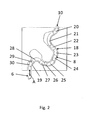
- Fig. 2 shows the endoscope head 8 in a meandering channel 18, such as a tortuous body opening.
- a meandering channel 18 such as a tortuous body opening.
- the distal end of the endoscope head 8, ie the endoscope tip 10 is inserted in the direction of the arrow A in the channel 18.
- a first section 20, which adjoins the endoscope tip 10 on the proximal side is bent or curved in such a way that the first bend 19 can be rounded.
- the section 20 is respectively steered or bent, that the following curves can be bypassed.
- the sections 21-30 of the endoscope head 8 adjoining the section 20 in the proximal direction can likewise be angled, wherein the sections 21-30 are always angled during further advancing in such a way that they follow the movement of the first section 20 so that the endoscope head 8 moves can move in a meandering motion through the channel 18.
- the deflection of the Sections 20 to 30 active by arranged in the sections actuators. This has the advantage that the friction on the walls of the channel 18 is reduced, since there occur much lower pressure forces. Thus, a slight advance of the instrument is possible overall, thereby reducing the risk of injury.
- the deflection of the sections 21 to 30 is preferably by a control device 32 (see Fig. 10 ).
- the control device controls in dependence on the feed in the direction A, the deflection of the sections 21 to 30 automatically, so that these areas are tracked to the movements of the first section 20, and overall results in the shown snaking movement.
- Fig. 3 shows schematically how the endoscope head 8 can bend or deflect in substantially any radial direction with respect to the longitudinal axis X. In this case, a bending by about 270 ° is possible, so that the endoscope tip 10 in the radial direction of the longitudinal axis X of the shaft 4 faces. So shows Fig. 3 the maximum possible deflection and the possible deflection directions of the endoscope head 8.
- the deflection of the endoscope head 8 is made possible by actuators arranged in the endoscope head 8. This will be closer to the FIGS. 4 to 9 explained.
- the endoscope head 8 is formed as an integrated component, which combines several functions.
- the peripheral wall 34 and the end wall 36 on the endoscope tip 10 are manufactured in one piece from a polymer material.
- This polymer material is an electroactive polymer, ie a polymer which changes its shape or extent as a function of an applied electrical voltage.
- the distal-side interfaces of the instrument are integrated. In the example shown, these are a probe channel 38, an optic 40, and light guides 42 and 44. All of these channels and elements terminate in the endoscope tip 10 and have there on their distal-side interfaces.
- image sensors, LED light sources and the like could be integrated into the frontal wall 36 as distal-side interfaces.
- the front-side wall 36 and the peripheral wall 34 form the mechanically supporting structure of the endoscope head 8. That is, the peripheral wall 34 forms in this area the tube of the shaft, which also limits the shaft to the outside at the same time.
- Electrodes 46 and 48 are embedded in the electroactive polymer.
- the electrodes 46 form control electrodes, while the electrodes 48 represent reference electrodes. Between the electrodes 46 and 48, which are alternately spaced apart in the polymer 34, a voltage is applied, whereby the expansion of the polymer between the electrodes 46 and 48 changes. As a result, change in length in the direction of the longitudinal axis X can be caused. Since the electrodes 46 and 48 are arranged in electrode groups which are arranged at different points of the circumference in the peripheral wall 34, these changes in length can be selectively caused by corresponding electrical voltages on the electrodes in individual peripheral regions, whereby a deflection in the previously achieved manner is achieved.
- the electrodes 46 and 48 are connected via control lines 50 to the control device 32.
- the control lines 50 are also embedded in the polymer of the wall 34 and extend in the proximal direction into the handle 2, from where they are then electrically conductively connected to the control device 32.
- the actuators which are formed from the electrodes 46 and 48 and the polymer between the electrodes, ie the material of the wall 34, very space-saving in arranged the instrument.
- the actuators can be integrated into the wall 34 and the wall itself acts as an actuator.
- the free lumen in the interior for the channels, light guides and the like can be kept very large.
- the structure of the instrument is very simple, since the endoscope head is integrally formed.
- the endoscope tip 10 can be cast together with the peripheral wall 34 of the electroactive polymer, wherein at the same time required for the actuators electrodes 46 and 48 are poured with their control lines 50 in the polymer. That is, it eliminates an additional assembly for the actuators and the endoscope tip 10th
- Electrodes 46 and 48 Since the distance between the individual electrodes 46 and 48 is very small, the achievable change in length between the individual electrodes 46 and 48 is very small. For this reason, several electrodes are combined into electrode groups. In this case, the electrodes of an electrode group are then preferably applied together with voltage, so that the individual changes in length between the individual electrodes in the polymer add up to a greater change in length overall.
- These electrode groups form Akforfelder 52, which schematically in Fig. 4 are shown. In Fig. 4 the electrodes are not shown, but only the areas (actuator fields 52) in which the electrodes are embedded in the circumferential wall 34. In this case, the electrodes, as described above, are preferably cast into the peripheral wall, so that a circumferential wall is produced, which is manufactured in one piece from polymer material.
- the Aktorfelder 52 are arranged on the one hand, that in the circumferential direction of the wall 34 a plurality of Aktorfelder 52 are distributed. That is, in this direction, the actuator fields 52 are located at different circumferential positions, preferably evenly distributed. This allows the Deflection in a certain direction, as in Fig. 3 shown schematically can be achieved. Depending on which of the Aktorfelder 52, is applied in a cross-sectional plane with voltage, the shaft is deflected in the corresponding direction. In Fig. 4 As shown, three actuator fields 52 are distributed over the circumference. If only these three actuator fields 52 were selectively energized, deflection would only be possible in three radial directions.
- the actuator fields 52 are also arranged one behind the other in the axial direction.
- the sections 20 to 30 are created in the axial direction, which can be deflected differently, whereby the serpentine bendability of the instrument is realized, as based on Fig. 2 explained.
- FIG. 8 shows in a circumferential plane three Aktorfelder 52, which are formed by alternately arranged electrodes 46 and 48.
- a comb-shaped electrode structure is selected. That is, the electrodes 46 extend from axial conductors 54 in the circumferential direction each substantially over a third circle.
- the electrodes 48 starting from axial conductors 56 each also in the circumferential direction substantially over a third circle.
- the electrodes 46 and 48 extend from the axial conductors 54 and 56 in opposite directions, so that the electrodes 46 engage in the free spaces between the electrodes 48 and vice versa, the electrodes 48 engage in the free spaces between the electrodes 46. Since all the electrodes 46 of an actuator field 52 are connected to the associated axial conductor 54, these electrodes 46 are all supplied together with voltage to the electrodes 48. The electrodes 48 of an actuator field 52 are each connected in common with an axial conductor 56. The axial conductors 54 and 56 extend in the axial direction to the proximal end of the shaft as control lines 50th
- Fig. 9 shows a second possible electrode arrangement.
- the reference electrode 48 ' as a continuous helical or helical reference electrode 48' is formed. At one end, this electrode 48 'is connected to an axial conductor 56', which forms a control line 50 in the proximal direction.
- the actuator fields 52 are arranged distributed in the circumferential direction, which essentially extend in each case over a third circle.
- the control electrodes 46 ' are each segmented and also extend substantially over a third of a circle.
- arcuate control electrodes 46 ' are arranged at a distance from one another in each actuator field 52 in such a way that they engage in the free spaces between the helical turns of the continuous reference electrode 48'.
- the arcuate control electrodes 46 ' extending from axial conductors 54' in the radial direction web-shaped to the outside.
- the axial conductors 54 ' extend in the proximal direction as control lines 50 on.
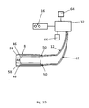
- the force sensors 58 are each formed of two electrodes 60 and 62 embedded in the polymeric material of the walls 34 and 36 and spaced from each other.
- the electrodes 60 and 62 are connected in the axial direction with control lines 50, which extend to the proximal end of the instrument and are then connected via the connecting cable 12 to the control device 32.
- the force sensors 58 operate in a manner that changes their capacitance and / or electrical resistance as the polymeric material between the electrodes 60 and 62 deforms, which may be detected by the electrodes 60 and 62.
- the electrodes 60 and 62 are connected via control lines 50 to the control device 32, which detects the resistance or the capacitance between the electrodes 60 and 62. Knowing the modulus of elasticity of the polymer of the wall 34 and 36 can then be inferred depending on the detected capacitance or the electrical resistance to the applied force. Because the electrodes 60 and 62 are arranged inclined to the longitudinal axis X and the end face of the endoscope tip 10, here at an angle of substantially 45 °, forces can be detected by the force sensors 58 with components from the axial direction and radial direction. About that In addition, a plurality of force sensors 58 are arranged distributed over the circumference of the endoscope tip 10.
- the endoscope can be deflected by deflecting the endoscope head 8, first of the region 20 (see FIG Fig. 2 ), avoid this obstacle.
- the controller 32 is adapted to allow automatic deflection when the endoscope tip 10 encounters an obstacle.
- the control device 32 detects in which circumferential area the obstacle lies, depending on which of the force sensors 58 signals an increased force.
- the electrodes 46 and 48 are acted upon in those Aktorfelder 52 with voltage, which causes a deflection of the endoscope head 8 in one of the detected force istgewantdte or opposite radial direction. In this way, the endoscope tip 10 is deflected or bent away from the obstacle in the radial direction, so that the endoscope tip 10 and the further feed the endoscope head 8 can be guided around the obstacle.
- the control device 32 can recognize in which direction the endoscope head 8 has to be deflected in order to pass the obstacle.
- an alarm signal can then be output by the control device 32 via an alarm device 64, which signals the obstacle to an operator.
- the alarm device 64 can be designed as a visual display, as an acoustic display, as an acoustic detector or as a tuneful detector.
- the haptic detector may generate a vibration in the handle or the like.
- the control device 32 controls the feed automatically. In such a case, in a frontal collision, the feed can be stopped.
- a detection device 66 can be provided for detecting the traveled feed path. This can be arranged, for example, in a fixed point to which the relative axial movement of the shaft 4 is detected. Depending on the expansion or compression of the polymer between the electrodes 46, 46 'and 48, 48', the electrical resistance of the polymer changes, which can be detected via the electrodes 46, 46 'and 48, 48'.
Landscapes
- Health & Medical Sciences (AREA)
- Life Sciences & Earth Sciences (AREA)
- Surgery (AREA)
- Physics & Mathematics (AREA)
- Engineering & Computer Science (AREA)
- Medical Informatics (AREA)
- Animal Behavior & Ethology (AREA)
- Veterinary Medicine (AREA)
- Optics & Photonics (AREA)
- Public Health (AREA)
- Biomedical Technology (AREA)
- Heart & Thoracic Surgery (AREA)
- Biophysics (AREA)
- Molecular Biology (AREA)
- Pathology (AREA)
- General Health & Medical Sciences (AREA)
- Nuclear Medicine, Radiotherapy & Molecular Imaging (AREA)
- Radiology & Medical Imaging (AREA)
- Signal Processing (AREA)
- Astronomy & Astrophysics (AREA)
- General Physics & Mathematics (AREA)
- Human Computer Interaction (AREA)
- Endoscopes (AREA)
- Instruments For Viewing The Inside Of Hollow Bodies (AREA)
Applications Claiming Priority (1)
| Application Number | Priority Date | Filing Date | Title |
|---|---|---|---|
| DE102008047776A DE102008047776B4 (de) | 2008-09-17 | 2008-09-17 | Endoskopisches Instrument |
Publications (3)
| Publication Number | Publication Date |
|---|---|
| EP2165641A2 true EP2165641A2 (fr) | 2010-03-24 |
| EP2165641A3 EP2165641A3 (fr) | 2012-04-04 |
| EP2165641B1 EP2165641B1 (fr) | 2013-02-13 |
Family
ID=41506390
Family Applications (1)
| Application Number | Title | Priority Date | Filing Date |
|---|---|---|---|
| EP09009468A Not-in-force EP2165641B1 (fr) | 2008-09-17 | 2009-07-22 | Instrument endoscopique |
Country Status (4)
| Country | Link |
|---|---|
| US (1) | US8366605B2 (fr) |
| EP (1) | EP2165641B1 (fr) |
| JP (1) | JP5377184B2 (fr) |
| DE (1) | DE102008047776B4 (fr) |
Cited By (3)
| Publication number | Priority date | Publication date | Assignee | Title |
|---|---|---|---|---|
| EP2281499A1 (fr) * | 2009-08-06 | 2011-02-09 | Richard Wolf GmbH | Instrument endoscopique |
| EP2583616A4 (fr) * | 2011-03-29 | 2013-06-26 | Olympus Medical Systems Corp | Endoscope |
| EP2706903A4 (fr) * | 2011-05-13 | 2014-11-05 | Intuitive Surgical Operations | Système médical avec multiples modes de fonctionnement pour diriger un instrument médical à travers des passages corporels reliés |
Families Citing this family (19)
| Publication number | Priority date | Publication date | Assignee | Title |
|---|---|---|---|---|
| DE102010009003B4 (de) | 2010-02-24 | 2014-05-15 | Richard Wolf Gmbh | Endoskopisches Instrument |
| DE102010023519B4 (de) | 2010-06-11 | 2016-11-10 | Richard Wolf Gmbh | Endoskopisches Instrument |
| WO2012027581A2 (fr) * | 2010-08-27 | 2012-03-01 | Massachusetts Institute Of Technology | Endoscope jetable à extrémité commandée |
| US9956042B2 (en) | 2012-01-13 | 2018-05-01 | Vanderbilt University | Systems and methods for robot-assisted transurethral exploration and intervention |
| WO2013158983A1 (fr) | 2012-04-20 | 2013-10-24 | Vanderbilt University | Dispositif robotique pour l'établissement d'un canal d'accès |
| US9687303B2 (en) | 2012-04-20 | 2017-06-27 | Vanderbilt University | Dexterous wrists for surgical intervention |
| WO2013158978A1 (fr) * | 2012-04-20 | 2013-10-24 | Vanderbilt University | Procédé et système pour l'insertion souple de robots continuum |
| US9539726B2 (en) | 2012-04-20 | 2017-01-10 | Vanderbilt University | Systems and methods for safe compliant insertion and hybrid force/motion telemanipulation of continuum robots |
| US9333650B2 (en) | 2012-05-11 | 2016-05-10 | Vanderbilt University | Method and system for contact detection and contact localization along continuum robots |
| US9117347B2 (en) * | 2013-02-25 | 2015-08-25 | Nokia Technologies Oy | Method and apparatus for a flexible housing |
| US10743750B2 (en) | 2014-04-28 | 2020-08-18 | Massachusetts Institute Of Technology | Multi-link modular continuum robotic endoscope system |
| DE102014210281B4 (de) * | 2014-05-30 | 2025-01-02 | Digital Endoscopy Gmbh | Rohrelement für ein endoskop, endoskop mit diesem und herstellverfahren für ein rohrelement |
| US11793394B2 (en) | 2016-12-02 | 2023-10-24 | Vanderbilt University | Steerable endoscope with continuum manipulator |
| WO2019055701A1 (fr) | 2017-09-13 | 2019-03-21 | Vanderbilt University | Robots continuum à mouvement multi-échelle par modulation d'équilibre |
| CN108030493A (zh) * | 2018-01-04 | 2018-05-15 | 科塞尔医疗科技(苏州)有限公司 | 一种用于环肺静脉的电生理导管 |
| WO2020049718A1 (fr) * | 2018-09-07 | 2020-03-12 | オリンパス株式会社 | Système de manipulateur |
| WO2020070851A1 (fr) * | 2018-10-04 | 2020-04-09 | オリンパス株式会社 | Partie courbure d'endoscope |
| US11300480B2 (en) * | 2020-02-28 | 2022-04-12 | Baker Hughes Oilfield Operations Llc | Articulated non-destructive testing device having a plurality of actuation systems and a method of articulating the device |
| WO2023203485A1 (fr) * | 2022-04-19 | 2023-10-26 | Boston Scientific Medical Device Limited | Ensembles de commande pour dispositifs médicaux et procédés d'utilisation associés |
Citations (2)
| Publication number | Priority date | Publication date | Assignee | Title |
|---|---|---|---|---|
| US20060258912A1 (en) | 2000-04-03 | 2006-11-16 | Amir Belson | Activated polymer articulated instruments and methods of insertion |
| EP1884185A1 (fr) | 2005-05-24 | 2008-02-06 | Olympus Medical Systems Corp. | Endoscope |
Family Cites Families (14)
| Publication number | Priority date | Publication date | Assignee | Title |
|---|---|---|---|---|
| JPH0576599A (ja) * | 1991-09-17 | 1993-03-30 | Olympus Optical Co Ltd | 医療用チユーブ |
| JPH0576481A (ja) * | 1991-09-17 | 1993-03-30 | Olympus Optical Co Ltd | メカノケミカルアクチユエータ及び医療用チユーブ |
| US6891317B2 (en) * | 2001-05-22 | 2005-05-10 | Sri International | Rolled electroactive polymers |
| US6809462B2 (en) * | 2000-04-05 | 2004-10-26 | Sri International | Electroactive polymer sensors |
| US6586859B2 (en) | 2000-04-05 | 2003-07-01 | Sri International | Electroactive polymer animated devices |
| US6770027B2 (en) * | 2001-10-05 | 2004-08-03 | Scimed Life Systems, Inc. | Robotic endoscope with wireless interface |
| US9808597B2 (en) * | 2002-09-12 | 2017-11-07 | Intuitive Surgical Operations, Inc. | Shape-transferring cannula system and method of use |
| US20040068161A1 (en) * | 2002-10-02 | 2004-04-08 | Couvillon Lucien Alfred | Thrombolysis catheter |
| US6936003B2 (en) * | 2002-10-29 | 2005-08-30 | Given Imaging Ltd | In-vivo extendable element device and system, and method of use |
| CN1870930A (zh) * | 2003-08-20 | 2006-11-29 | 新引导系统公司 | 活化聚合物关节连接的器械及插入方法 |
| US7744619B2 (en) * | 2004-02-24 | 2010-06-29 | Boston Scientific Scimed, Inc. | Rotatable catheter assembly |
| US20060025812A1 (en) * | 2004-07-28 | 2006-02-02 | Ethicon Endo-Surgery, Inc. | Surgical instrument incorporating an electrically actuated pivoting articulation mechanism |
| EP2289591A3 (fr) * | 2005-06-14 | 2012-01-04 | Olympus Medical Systems Corp. | Instrument de traitement endoscope et appareil d'instrument de traitement pour endoscope |
| EP1957141A1 (fr) * | 2005-11-17 | 2008-08-20 | MicroMuscle AB | Dispositifs medicaux et procedes de fabrication et d utilisation |
-
2008
- 2008-09-17 DE DE102008047776A patent/DE102008047776B4/de not_active Expired - Fee Related
-
2009
- 2009-07-22 EP EP09009468A patent/EP2165641B1/fr not_active Not-in-force
- 2009-09-14 JP JP2009211556A patent/JP5377184B2/ja not_active Expired - Fee Related
- 2009-09-16 US US12/560,764 patent/US8366605B2/en not_active Expired - Fee Related
Patent Citations (2)
| Publication number | Priority date | Publication date | Assignee | Title |
|---|---|---|---|---|
| US20060258912A1 (en) | 2000-04-03 | 2006-11-16 | Amir Belson | Activated polymer articulated instruments and methods of insertion |
| EP1884185A1 (fr) | 2005-05-24 | 2008-02-06 | Olympus Medical Systems Corp. | Endoscope |
Cited By (7)
| Publication number | Priority date | Publication date | Assignee | Title |
|---|---|---|---|---|
| EP2281499A1 (fr) * | 2009-08-06 | 2011-02-09 | Richard Wolf GmbH | Instrument endoscopique |
| EP2583616A4 (fr) * | 2011-03-29 | 2013-06-26 | Olympus Medical Systems Corp | Endoscope |
| US8708892B2 (en) | 2011-03-29 | 2014-04-29 | Olympus Medical Systems Corp. | Endoscope with controlled bending sections |
| EP2706903A4 (fr) * | 2011-05-13 | 2014-11-05 | Intuitive Surgical Operations | Système médical avec multiples modes de fonctionnement pour diriger un instrument médical à travers des passages corporels reliés |
| US9572481B2 (en) | 2011-05-13 | 2017-02-21 | Intuitive Surgical Operations, Inc. | Medical system with multiple operating modes for steering a medical instrument through linked body passages |
| US11490793B2 (en) | 2011-05-13 | 2022-11-08 | Intuitive Surgical Operations, Inc. | Medical system with multiple operating modes for steering a medical instrument through linked body passages |
| US12551092B2 (en) | 2011-05-13 | 2026-02-17 | Intuitive Surgical Operations, Inc. | Medical system with multiple operating modes for steering a medical instrument through linked body passages |
Also Published As
| Publication number | Publication date |
|---|---|
| JP2010069298A (ja) | 2010-04-02 |
| DE102008047776B4 (de) | 2012-11-22 |
| DE102008047776A1 (de) | 2010-03-25 |
| EP2165641B1 (fr) | 2013-02-13 |
| US20100069719A1 (en) | 2010-03-18 |
| US8366605B2 (en) | 2013-02-05 |
| JP5377184B2 (ja) | 2013-12-25 |
| EP2165641A3 (fr) | 2012-04-04 |
Similar Documents
| Publication | Publication Date | Title |
|---|---|---|
| EP2165641B1 (fr) | Instrument endoscopique | |
| EP2464405B1 (fr) | Instrument médical à cathéter | |
| EP2702926B1 (fr) | Tige pour un endoscope flexible ou un instrument endoscopique flexible | |
| EP1342446B1 (fr) | Endoscope avec une extrémité distale flexible | |
| DE19882093B4 (de) | Ultraschallkatheteranordnug | |
| DE10142604B4 (de) | Flexibles Rohr eines Endoskops und mit dem flexiblen Rohr ausgerüstetes elektronisches Endoskop | |
| DE102009041510A1 (de) | Endoskopisches Instrument | |
| EP1604607B1 (fr) | Partie flexible d'un tube d'introduction d'un endoscope et procédé de fabrication | |
| EP2324755B1 (fr) | Endoscope doté d'un arbre d'endoscope flexible | |
| DE4438944C2 (de) | Endoskop | |
| DE102005014529B4 (de) | Ultraschallendoskop | |
| DE102012220578A1 (de) | Endoskop mit schwenkbarer Optik | |
| DE102009037046A1 (de) | Rohrförmiger Schaft eines chirurgischen Instruments sowie chirurgisches Instrument | |
| DE102007002401A1 (de) | Medizinische Untersuchungs- oder Interventionseinrichtung | |
| EP2689716B1 (fr) | Endoscope | |
| EP3534770B1 (fr) | Élément à canal de travail, endoscope ayant un élément à canal de travail et procédé pour uiliser un canal de travail dans un endoscope | |
| DE102013101202A1 (de) | Endoskopisches Instrument | |
| WO2011079897A1 (fr) | Commande d'une tige tubulaire d'un instrument chirurgical | |
| DE102009060718A1 (de) | Endoskopisches Instrument | |
| EP2674098A1 (fr) | Tige pour un endoscope flexible ou un instrument endoscopique flexible | |
| DE112016006985T5 (de) | Einführvorrichtung für einen flexiblen Tubus | |
| DE3435136C2 (fr) | ||
| DE102017117094A1 (de) | Individualisierbare Darstellung einer Umgebung eines Kraftfahrzeugs durch eine Fahrerassistenzvorrichtung | |
| DE102009037045A1 (de) | Rohrförmiger Schaft eines chirurgischen Instruments | |
| DE102014107430A1 (de) | Flexibles Endoskop |
Legal Events
| Date | Code | Title | Description |
|---|---|---|---|
| PUAI | Public reference made under article 153(3) epc to a published international application that has entered the european phase |
Free format text: ORIGINAL CODE: 0009012 |
|
| AK | Designated contracting states |
Kind code of ref document: A2 Designated state(s): AT BE BG CH CY CZ DE DK EE ES FI FR GB GR HR HU IE IS IT LI LT LU LV MC MK MT NL NO PL PT RO SE SI SK SM TR |
|
| AX | Request for extension of the european patent |
Extension state: AL BA RS |
|
| PUAL | Search report despatched |
Free format text: ORIGINAL CODE: 0009013 |
|
| AK | Designated contracting states |
Kind code of ref document: A3 Designated state(s): AT BE BG CH CY CZ DE DK EE ES FI FR GB GR HR HU IE IS IT LI LT LU LV MC MK MT NL NO PL PT RO SE SI SK SM TR |
|
| AX | Request for extension of the european patent |
Extension state: AL BA RS |
|
| RIC1 | Information provided on ipc code assigned before grant |
Ipc: A61B 1/005 20060101AFI20120229BHEP |
|
| 17P | Request for examination filed |
Effective date: 20120524 |
|
| GRAP | Despatch of communication of intention to grant a patent |
Free format text: ORIGINAL CODE: EPIDOSNIGR1 |
|
| GRAS | Grant fee paid |
Free format text: ORIGINAL CODE: EPIDOSNIGR3 |
|
| GRAA | (expected) grant |
Free format text: ORIGINAL CODE: 0009210 |
|
| AK | Designated contracting states |
Kind code of ref document: B1 Designated state(s): AT BE BG CH CY CZ DE DK EE ES FI FR GB GR HR HU IE IS IT LI LT LU LV MC MK MT NL NO PL PT RO SE SI SK SM TR |
|
| REG | Reference to a national code |
Ref country code: GB Ref legal event code: FG4D Free format text: NOT ENGLISH |
|
| REG | Reference to a national code |
Ref country code: AT Ref legal event code: REF Ref document number: 596026 Country of ref document: AT Kind code of ref document: T Effective date: 20130215 |
|
| REG | Reference to a national code |
Ref country code: IE Ref legal event code: FG4D Free format text: LANGUAGE OF EP DOCUMENT: GERMAN |
|
| REG | Reference to a national code |
Ref country code: CH Ref legal event code: NV Representative=s name: ISLER AND PEDRAZZINI AG, CH |
|
| REG | Reference to a national code |
Ref country code: DE Ref legal event code: R096 Ref document number: 502009006188 Country of ref document: DE Effective date: 20130411 |
|
| REG | Reference to a national code |
Ref country code: NL Ref legal event code: T3 |
|
| REG | Reference to a national code |
Ref country code: LT Ref legal event code: MG4D |
|
| PG25 | Lapsed in a contracting state [announced via postgrant information from national office to epo] |
Ref country code: ES Free format text: LAPSE BECAUSE OF FAILURE TO SUBMIT A TRANSLATION OF THE DESCRIPTION OR TO PAY THE FEE WITHIN THE PRESCRIBED TIME-LIMIT Effective date: 20130524 Ref country code: BG Free format text: LAPSE BECAUSE OF FAILURE TO SUBMIT A TRANSLATION OF THE DESCRIPTION OR TO PAY THE FEE WITHIN THE PRESCRIBED TIME-LIMIT Effective date: 20130513 Ref country code: SE Free format text: LAPSE BECAUSE OF FAILURE TO SUBMIT A TRANSLATION OF THE DESCRIPTION OR TO PAY THE FEE WITHIN THE PRESCRIBED TIME-LIMIT Effective date: 20130213 Ref country code: LT Free format text: LAPSE BECAUSE OF FAILURE TO SUBMIT A TRANSLATION OF THE DESCRIPTION OR TO PAY THE FEE WITHIN THE PRESCRIBED TIME-LIMIT Effective date: 20130213 Ref country code: IS Free format text: LAPSE BECAUSE OF FAILURE TO SUBMIT A TRANSLATION OF THE DESCRIPTION OR TO PAY THE FEE WITHIN THE PRESCRIBED TIME-LIMIT Effective date: 20130613 Ref country code: NO Free format text: LAPSE BECAUSE OF FAILURE TO SUBMIT A TRANSLATION OF THE DESCRIPTION OR TO PAY THE FEE WITHIN THE PRESCRIBED TIME-LIMIT Effective date: 20130513 |
|
| PG25 | Lapsed in a contracting state [announced via postgrant information from national office to epo] |
Ref country code: GR Free format text: LAPSE BECAUSE OF FAILURE TO SUBMIT A TRANSLATION OF THE DESCRIPTION OR TO PAY THE FEE WITHIN THE PRESCRIBED TIME-LIMIT Effective date: 20130514 Ref country code: FI Free format text: LAPSE BECAUSE OF FAILURE TO SUBMIT A TRANSLATION OF THE DESCRIPTION OR TO PAY THE FEE WITHIN THE PRESCRIBED TIME-LIMIT Effective date: 20130213 Ref country code: SI Free format text: LAPSE BECAUSE OF FAILURE TO SUBMIT A TRANSLATION OF THE DESCRIPTION OR TO PAY THE FEE WITHIN THE PRESCRIBED TIME-LIMIT Effective date: 20130213 Ref country code: PT Free format text: LAPSE BECAUSE OF FAILURE TO SUBMIT A TRANSLATION OF THE DESCRIPTION OR TO PAY THE FEE WITHIN THE PRESCRIBED TIME-LIMIT Effective date: 20130613 Ref country code: PL Free format text: LAPSE BECAUSE OF FAILURE TO SUBMIT A TRANSLATION OF THE DESCRIPTION OR TO PAY THE FEE WITHIN THE PRESCRIBED TIME-LIMIT Effective date: 20130213 Ref country code: LV Free format text: LAPSE BECAUSE OF FAILURE TO SUBMIT A TRANSLATION OF THE DESCRIPTION OR TO PAY THE FEE WITHIN THE PRESCRIBED TIME-LIMIT Effective date: 20130213 |
|
| PGFP | Annual fee paid to national office [announced via postgrant information from national office to epo] |
Ref country code: IT Payment date: 20130521 Year of fee payment: 5 Ref country code: BE Payment date: 20130527 Year of fee payment: 5 Ref country code: FR Payment date: 20130604 Year of fee payment: 5 |
|
| PG25 | Lapsed in a contracting state [announced via postgrant information from national office to epo] |
Ref country code: HR Free format text: LAPSE BECAUSE OF FAILURE TO SUBMIT A TRANSLATION OF THE DESCRIPTION OR TO PAY THE FEE WITHIN THE PRESCRIBED TIME-LIMIT Effective date: 20130213 |
|
| PG25 | Lapsed in a contracting state [announced via postgrant information from national office to epo] |
Ref country code: EE Free format text: LAPSE BECAUSE OF FAILURE TO SUBMIT A TRANSLATION OF THE DESCRIPTION OR TO PAY THE FEE WITHIN THE PRESCRIBED TIME-LIMIT Effective date: 20130213 Ref country code: SK Free format text: LAPSE BECAUSE OF FAILURE TO SUBMIT A TRANSLATION OF THE DESCRIPTION OR TO PAY THE FEE WITHIN THE PRESCRIBED TIME-LIMIT Effective date: 20130213 Ref country code: RO Free format text: LAPSE BECAUSE OF FAILURE TO SUBMIT A TRANSLATION OF THE DESCRIPTION OR TO PAY THE FEE WITHIN THE PRESCRIBED TIME-LIMIT Effective date: 20130213 Ref country code: DK Free format text: LAPSE BECAUSE OF FAILURE TO SUBMIT A TRANSLATION OF THE DESCRIPTION OR TO PAY THE FEE WITHIN THE PRESCRIBED TIME-LIMIT Effective date: 20130213 Ref country code: CZ Free format text: LAPSE BECAUSE OF FAILURE TO SUBMIT A TRANSLATION OF THE DESCRIPTION OR TO PAY THE FEE WITHIN THE PRESCRIBED TIME-LIMIT Effective date: 20130213 |
|
| PGFP | Annual fee paid to national office [announced via postgrant information from national office to epo] |
Ref country code: NL Payment date: 20130716 Year of fee payment: 5 Ref country code: CH Payment date: 20130711 Year of fee payment: 5 |
|
| PGFP | Annual fee paid to national office [announced via postgrant information from national office to epo] |
Ref country code: GB Payment date: 20130705 Year of fee payment: 5 |
|
| PLBE | No opposition filed within time limit |
Free format text: ORIGINAL CODE: 0009261 |
|
| STAA | Information on the status of an ep patent application or granted ep patent |
Free format text: STATUS: NO OPPOSITION FILED WITHIN TIME LIMIT |
|
| 26N | No opposition filed |
Effective date: 20131114 |
|
| REG | Reference to a national code |
Ref country code: DE Ref legal event code: R097 Ref document number: 502009006188 Country of ref document: DE Effective date: 20131114 |
|
| PG25 | Lapsed in a contracting state [announced via postgrant information from national office to epo] |
Ref country code: MC Free format text: LAPSE BECAUSE OF FAILURE TO SUBMIT A TRANSLATION OF THE DESCRIPTION OR TO PAY THE FEE WITHIN THE PRESCRIBED TIME-LIMIT Effective date: 20130213 |
|
| REG | Reference to a national code |
Ref country code: IE Ref legal event code: MM4A |
|
| PG25 | Lapsed in a contracting state [announced via postgrant information from national office to epo] |
Ref country code: IE Free format text: LAPSE BECAUSE OF NON-PAYMENT OF DUE FEES Effective date: 20130722 |
|
| REG | Reference to a national code |
Ref country code: NL Ref legal event code: V1 Effective date: 20150201 |
|
| REG | Reference to a national code |
Ref country code: CH Ref legal event code: PL |
|
| GBPC | Gb: european patent ceased through non-payment of renewal fee |
Effective date: 20140722 |
|
| PG25 | Lapsed in a contracting state [announced via postgrant information from national office to epo] |
Ref country code: NL Free format text: LAPSE BECAUSE OF NON-PAYMENT OF DUE FEES Effective date: 20150201 |
|
| REG | Reference to a national code |
Ref country code: FR Ref legal event code: ST Effective date: 20150331 |
|
| PG25 | Lapsed in a contracting state [announced via postgrant information from national office to epo] |
Ref country code: IT Free format text: LAPSE BECAUSE OF NON-PAYMENT OF DUE FEES Effective date: 20140722 Ref country code: LI Free format text: LAPSE BECAUSE OF NON-PAYMENT OF DUE FEES Effective date: 20140731 Ref country code: CH Free format text: LAPSE BECAUSE OF NON-PAYMENT OF DUE FEES Effective date: 20140731 |
|
| PG25 | Lapsed in a contracting state [announced via postgrant information from national office to epo] |
Ref country code: FR Free format text: LAPSE BECAUSE OF NON-PAYMENT OF DUE FEES Effective date: 20140731 Ref country code: GB Free format text: LAPSE BECAUSE OF NON-PAYMENT OF DUE FEES Effective date: 20140722 Ref country code: SM Free format text: LAPSE BECAUSE OF FAILURE TO SUBMIT A TRANSLATION OF THE DESCRIPTION OR TO PAY THE FEE WITHIN THE PRESCRIBED TIME-LIMIT Effective date: 20130213 |
|
| PG25 | Lapsed in a contracting state [announced via postgrant information from national office to epo] |
Ref country code: CY Free format text: LAPSE BECAUSE OF FAILURE TO SUBMIT A TRANSLATION OF THE DESCRIPTION OR TO PAY THE FEE WITHIN THE PRESCRIBED TIME-LIMIT Effective date: 20130213 Ref country code: TR Free format text: LAPSE BECAUSE OF FAILURE TO SUBMIT A TRANSLATION OF THE DESCRIPTION OR TO PAY THE FEE WITHIN THE PRESCRIBED TIME-LIMIT Effective date: 20130213 Ref country code: MT Free format text: LAPSE BECAUSE OF FAILURE TO SUBMIT A TRANSLATION OF THE DESCRIPTION OR TO PAY THE FEE WITHIN THE PRESCRIBED TIME-LIMIT Effective date: 20130213 |
|
| PG25 | Lapsed in a contracting state [announced via postgrant information from national office to epo] |
Ref country code: LU Free format text: LAPSE BECAUSE OF NON-PAYMENT OF DUE FEES Effective date: 20130722 Ref country code: HU Free format text: LAPSE BECAUSE OF FAILURE TO SUBMIT A TRANSLATION OF THE DESCRIPTION OR TO PAY THE FEE WITHIN THE PRESCRIBED TIME-LIMIT; INVALID AB INITIO Effective date: 20090722 Ref country code: MK Free format text: LAPSE BECAUSE OF FAILURE TO SUBMIT A TRANSLATION OF THE DESCRIPTION OR TO PAY THE FEE WITHIN THE PRESCRIBED TIME-LIMIT Effective date: 20130213 |
|
| REG | Reference to a national code |
Ref country code: AT Ref legal event code: MM01 Ref document number: 596026 Country of ref document: AT Kind code of ref document: T Effective date: 20140722 |
|
| PG25 | Lapsed in a contracting state [announced via postgrant information from national office to epo] |
Ref country code: AT Free format text: LAPSE BECAUSE OF NON-PAYMENT OF DUE FEES Effective date: 20140722 |
|
| PG25 | Lapsed in a contracting state [announced via postgrant information from national office to epo] |
Ref country code: BE Free format text: LAPSE BECAUSE OF NON-PAYMENT OF DUE FEES Effective date: 20140731 |
|
| REG | Reference to a national code |
Ref country code: DE Ref legal event code: R084 Ref document number: 502009006188 Country of ref document: DE |
|
| PGFP | Annual fee paid to national office [announced via postgrant information from national office to epo] |
Ref country code: DE Payment date: 20230724 Year of fee payment: 15 |
|
| REG | Reference to a national code |
Ref country code: DE Ref legal event code: R119 Ref document number: 502009006188 Country of ref document: DE |
|
| PG25 | Lapsed in a contracting state [announced via postgrant information from national office to epo] |
Ref country code: DE Free format text: LAPSE BECAUSE OF NON-PAYMENT OF DUE FEES Effective date: 20250201 |