EP2165683A1 - Einführungssystem zur Anwendung in Katheterstentvorrichtungen - Google Patents
Einführungssystem zur Anwendung in Katheterstentvorrichtungen Download PDFInfo
- Publication number
- EP2165683A1 EP2165683A1 EP09169903A EP09169903A EP2165683A1 EP 2165683 A1 EP2165683 A1 EP 2165683A1 EP 09169903 A EP09169903 A EP 09169903A EP 09169903 A EP09169903 A EP 09169903A EP 2165683 A1 EP2165683 A1 EP 2165683A1
- Authority
- EP
- European Patent Office
- Prior art keywords
- insertion system
- head part
- reference mark
- stent device
- holding means
- Prior art date
- Legal status (The legal status is an assumption and is not a legal conclusion. Google has not performed a legal analysis and makes no representation as to the accuracy of the status listed.)
- Granted
Links
Images



Classifications
-
- A—HUMAN NECESSITIES
- A61—MEDICAL OR VETERINARY SCIENCE; HYGIENE
- A61F—FILTERS IMPLANTABLE INTO BLOOD VESSELS; PROSTHESES; DEVICES PROVIDING PATENCY TO, OR PREVENTING COLLAPSING OF, TUBULAR STRUCTURES OF THE BODY, e.g. STENTS; ORTHOPAEDIC, NURSING OR CONTRACEPTIVE DEVICES; FOMENTATION; TREATMENT OR PROTECTION OF EYES OR EARS; BANDAGES, DRESSINGS OR ABSORBENT PADS; FIRST-AID KITS
- A61F2/00—Filters implantable into blood vessels; Prostheses, i.e. artificial substitutes or replacements for parts of the body; Appliances for connecting them with the body; Devices providing patency to, or preventing collapsing of, tubular structures of the body, e.g. stents
- A61F2/95—Instruments specially adapted for placement or removal of stents or stent-grafts
- A61F2/962—Instruments specially adapted for placement or removal of stents or stent-grafts having an outer sleeve
- A61F2/966—Instruments specially adapted for placement or removal of stents or stent-grafts having an outer sleeve with relative longitudinal movement between outer sleeve and prosthesis, e.g. using a push rod
-
- A—HUMAN NECESSITIES
- A61—MEDICAL OR VETERINARY SCIENCE; HYGIENE
- A61F—FILTERS IMPLANTABLE INTO BLOOD VESSELS; PROSTHESES; DEVICES PROVIDING PATENCY TO, OR PREVENTING COLLAPSING OF, TUBULAR STRUCTURES OF THE BODY, e.g. STENTS; ORTHOPAEDIC, NURSING OR CONTRACEPTIVE DEVICES; FOMENTATION; TREATMENT OR PROTECTION OF EYES OR EARS; BANDAGES, DRESSINGS OR ABSORBENT PADS; FIRST-AID KITS
- A61F2/00—Filters implantable into blood vessels; Prostheses, i.e. artificial substitutes or replacements for parts of the body; Appliances for connecting them with the body; Devices providing patency to, or preventing collapsing of, tubular structures of the body, e.g. stents
- A61F2/02—Prostheses implantable into the body
- A61F2/30—Joints
- A61F2002/30001—Additional features of subject-matter classified in A61F2/28, A61F2/30 and subgroups thereof
- A61F2002/30316—The prosthesis having different structural features at different locations within the same prosthesis; Connections between prosthetic parts; Special structural features of bone or joint prostheses not otherwise provided for
- A61F2002/30535—Special structural features of bone or joint prostheses not otherwise provided for
- A61F2002/30617—Visible markings for adjusting, locating or measuring
-
- A—HUMAN NECESSITIES
- A61—MEDICAL OR VETERINARY SCIENCE; HYGIENE
- A61F—FILTERS IMPLANTABLE INTO BLOOD VESSELS; PROSTHESES; DEVICES PROVIDING PATENCY TO, OR PREVENTING COLLAPSING OF, TUBULAR STRUCTURES OF THE BODY, e.g. STENTS; ORTHOPAEDIC, NURSING OR CONTRACEPTIVE DEVICES; FOMENTATION; TREATMENT OR PROTECTION OF EYES OR EARS; BANDAGES, DRESSINGS OR ABSORBENT PADS; FIRST-AID KITS
- A61F2/00—Filters implantable into blood vessels; Prostheses, i.e. artificial substitutes or replacements for parts of the body; Appliances for connecting them with the body; Devices providing patency to, or preventing collapsing of, tubular structures of the body, e.g. stents
- A61F2/95—Instruments specially adapted for placement or removal of stents or stent-grafts
- A61F2/962—Instruments specially adapted for placement or removal of stents or stent-grafts having an outer sleeve
- A61F2/966—Instruments specially adapted for placement or removal of stents or stent-grafts having an outer sleeve with relative longitudinal movement between outer sleeve and prosthesis, e.g. using a push rod
- A61F2002/9665—Instruments specially adapted for placement or removal of stents or stent-grafts having an outer sleeve with relative longitudinal movement between outer sleeve and prosthesis, e.g. using a push rod with additional retaining means
-
- A—HUMAN NECESSITIES
- A61—MEDICAL OR VETERINARY SCIENCE; HYGIENE
- A61F—FILTERS IMPLANTABLE INTO BLOOD VESSELS; PROSTHESES; DEVICES PROVIDING PATENCY TO, OR PREVENTING COLLAPSING OF, TUBULAR STRUCTURES OF THE BODY, e.g. STENTS; ORTHOPAEDIC, NURSING OR CONTRACEPTIVE DEVICES; FOMENTATION; TREATMENT OR PROTECTION OF EYES OR EARS; BANDAGES, DRESSINGS OR ABSORBENT PADS; FIRST-AID KITS
- A61F2250/00—Special features of prostheses classified in groups A61F2/00 - A61F2/26 or A61F2/82 or A61F9/00 or A61F11/00 or subgroups thereof
- A61F2250/0058—Additional features; Implant or prostheses properties not otherwise provided for
- A61F2250/0096—Markers and sensors for detecting a position or changes of a position of an implant, e.g. RF sensors, ultrasound markers
- A61F2250/0097—Visible markings, e.g. indicia
Definitions
- the present invention relates to an insertion system for release of a self-expanding stent device in a body vessel, comprising a first grip, which is fixedly connected to a shaft, a second grip, which is mounted on the shaft to be movable in axial direction, a sheath, which, in a distal portion thereof, keeps the stent device radially compressed and which is fixedly connected to the second grip, and a retention element, which is fixedly connected to the shaft and is guided in the sheath, wherein the retention element holds the stent device in its axial position relative to the first grip when the sheath is being retracted.
- Insertion systems and stent devices of this kind are known, for example, from US 5,026,377 A .
- stent devices are implanted into blood vessels for the treatment of damages in blood vessels like, for example, aneurysms.
- Such treatment is applied, for example, in the surgical reconstruction of major blood vessels, for example the descending part of the thoragic aorta, that cannot be treated by conventional surgical methods because of insufficient accessibility.
- Examples of indications which are to be treated in this way, and as a result of which the function of the vessels is greatly impaired or there is a danger of rupture of the vessels include blood vessel damage caused by disease or the like, acquired or congenital aneurysms or partial occlusions of the lumen of a blood vessel, for example by formation of pseudolumina.
- stent devices are known by means of which blood vessels, for example arteries, are kept open or widenings are excluded from the blood stream. These include stents and stent grafts.
- Stents generally comprise a tubular body which is inserted into the vessel and is expanded and fixed at the appropriate site in order to keep open the lumen of the vessel.
- Stent grafts comprise, for example, a series of stents or, respectively, a wire framework made of a self-expanding material.
- stents are understood to be individual self-expanding elements.
- the self-expanding elements or, respectively, the wire framework are connected to each other by a textile or PTFE tube, called a graft sleeve, to form a functional unit and in this way, analogous to the stents described above, they form a tubular body that supports the vessel walls.
- stent devices which, in addition to a stent graft, also comprise a woven prosthesis part, a so-called prosthesis cuff, attached to the proximal end of the stent graft.
- proximal designates as usual a side directed towards the user (operator)
- distal designates a side directed away from the user.
- Such a prosthesis cuff enables a secure surgical fixation of the stent device to the vessel wall and, by virtue of its relative flexibility, can be used as a vessel adapter for connecting an implanted stent graft to other vessel reconstruction implants or to a vessel itself, for example in vascular reconstruction of the aortic arch.
- the insertion system has a first grip, which is fixedly connected to a proximal end of a shaft. Further, a second grip, which is fixedly connected to a sheath, is arranged movably on the shaft.
- “fixedly” means that the connection between second grip and sheath is suitable for taking up tension, compression and torsion forces.
- a stent device Arranged between sheath and shaft there is a stent device, which is disposed inside the sheath and is radially compressed by the latter. The cross-section of the stent device is in this way greatly reduced, and it can be easily inserted into a vessel.
- the stent device When the sheath is then retracted relative to the stent device by a movement of the second grip, the stent device, by virtue of the resiliency of the metal frame or metal stent, expands back to its original shape in the portion of the stent device released from the sheath. The sleeve surface of the stent device is thereby stretched out and wedges itself within the blood vessel.
- the stent devices are first inserted into the blood vessel with the aid of catheters, which are advanced through the vessel lumen, and they are positioned at the correct location in the vessel.
- deployment position is understood as the whole area of a vessel filled by a stent device after expansion thereof.
- deployment zone is understood as a short proximal area of the deployment position at which the stent device is surgically connected to the vessel wall after expansion.
- the “deployment zone” designates the area of the insertion system at whose axial level, after expansion, the part of the stent device is located which is to be surgically connected to the vessel wall.
- the deployment zone is accordingly situated at the axial level of a proximal portion of the stent device compressed in the sheath.
- the deployment zone can be offset in proximal direction, relative to the proximal end of the stent device compressed in the sheath, to such an extent that it corresponds to the position of the distal portion of the prosthesis cuff after the expansion and unfolding of the stent device, if the stent device is to be connected to the vessel wall at the distal end of the prosthesis cuff portion after the expansion and subsequent unfolding of the prosthesis cuff portion.
- the deployment zone can be offset in distal direction, relative to the proximal end of the stent device compressed in the sheath, to such an extent that it corresponds to the position of the proximal portion of the stent device in its unfolded state.
- the correct position of the stent device can be monitored, for example, by X-ray markers.
- the continuous monitoring of the position by X-ray markers exposes the operator and patient to a certain amount of radiation.
- continuous monitoring of the position by X-ray markers is therefore not only an unnecessary risk but also extremely complicated, since there is no blood flow. This is because the patient is connected to a heart-lung machine during these operations such that the diseased vessel can be opened, because it is empty of blood.
- EP 1 943 988 A1 describes an insertion system for a stent device, in which positional control of the stent device is achieved by sensors provided on the insertion system or the stent device. These sensors operate on the basis of non-ionizing radiation, magnetic fields or pressure waves.
- EP 1 391 181 A1 describes an apparatus for virtual endoscopy, in which apparatus the position of a surgical instrument is determined by means of sensors provided on the surgical instrument, and the data acquired are transmitted to an imaging system for generating a virtual representation of the patient's body and the surgical instrument inserted therein.
- the technical complexity of the sensor systems results in high production costs, hence being especially disadvantageous in single-use surgical instruments such as insertion devices for stent devices.
- the sheath is retracted in the proximal direction.
- the stent device lies in contact with a retention element, which holds the stent device in its axial position relative to the first grip while, with the aid of the second grip, the sheath also enclosing the retention element is pulled off from the stent device to permit expansion thereof.
- the large amount of force to be applied is mainly caused by friction between the outer wall of the stent device, strongly compressed against its expansion forces, and the inner wall of the sheath.
- a disadvantage of this is that, for example with stent parts penetrating into the surrounding vessel wall, additional trauma may be caused.
- the known methods and devices do not offer any certainty of a proximal portion of the stent device coming into contact with the vessel wall at its predetermined landing zone. Consequently, in the event of incorrect handling by the operator, the stent device may shift out of position, for example in distal direction, which in some circumstances is associated with the formation of folds, for example in a graft sleeve. Such folds pose an additional risk in the area of the inner wall of a stent device that has been inserted in this way. Secure anchoring of the proximal end in the vessel wall is also made more difficult, and the imprecision of the proximal deployment position may compromise the overall success of the operation.
- this shifting of the stent device as a whole, or at its proximal end or distal end, can be avoided by not moving the stationary parts of the stent insertion system, especially the shaft and the first grip, relative to the deployment position, such that the deployment zone remains unchanged in position relative to the landing zone.
- the operator can ensure the unchanged position of the stent device relative to the body vessel, and, therefore, relative to the axial deployment position, only by precisely controlling the hold on the first grip of the stent insertion system.
- the second grip since he at the same time has to use his other hand on the second grip to carry out the withdrawal movement, there is a high probability of the withdrawal movement, or of compensatory movements in the opposite direction, causing the stent device to shift, at least partially, in axial direction relative to the predetermined landing zone. This shifting may compromise the success of the operation or even cause damage to the vessel wall.
- this object is achieved by an insertion system of the kind mentioned at the outset, wherein reference means with an optical reference mark are provided for continuous monitoring of the axial position of the stent device.
- the insertion system having reference means according to the invention is to be applied in surgical operations performed on locations inside the human body which during open surgery, are directly accessible and directly visible, i.e. without additional detection equipment, from outside the patient's body.
- the reference mark now provides a visual aid with which the operator can monitor compliance with the predetermined deployment position of the stent device and can thus continuously monitor the axial position of the catheter and thereby the position of the deployment zone relative to the landing zone.
- optical reference mark is to be understood here as a mark which is designed such that it can be detected by the naked eye during an operation. This means that the operator, for detecting the optical reference mark, does not require additional equipment such as detection apparatuses and/or sensors as well as display means.
- a stent device is to be understood as a stent, a stent arrangement, a stent graft, or a stent graft with attached prosthesis cuff.
- the present invention also makes the first use by an operator much easier.
- the reference means being designed such that they have a light source, for example a lamp or a light-emitting diode (LED) or a laser.
- a light source for example a lamp or a light-emitting diode (LED) or a laser.
- This light source can be integrated into the shaft or into the retention element, for example at the level of the deployment zone, such that the emitted light can be seen from outside through an at least partially translucent part of the shaft, of the stent device and/or of the sheath.
- electrical leads routed upwards through the shaft can connect the light source to an external energy source, or to an energy source integrated into the first grip or mounted removably on the first grip, and to control elements.
- materials with light-conducting properties can be incorporated into the shaft, such that a light source, which is connected to an energy source and which is integrated for example into the first grip or mounted removably on the first grip, can be connected to the light-conducting materials in such a way that the emitted light is conveyed through the shaft until it strikes a refraction element at the level of the deployment zone, which element refracts the light such that it can be seen from outside through an at least partially translucent part of the shaft, of the stent device and/or of the sheath.
- the reference means comprise a physical reference mark.
- a "physical reference” mark is understood to be a reference mark that is formed from a body, which is placed near or at the vessel stump to be stented and which can there be seen with the naked eye, and, moreover, can be haptically detected inside the location to be treated without additional detection means required.
- the reference mark is arranged at the insertion system to be proximal to the stent device.
- the operator can continuously - or whenever this might be useful or necessary during an intervention - determine the position of the physical reference mark and thus monitor the axial position of the stent device during deployment thereof, just by touching or feeling the reference mark.
- the operator is at all times well able to see or at least feel a physical reference mark, for example even when viewing conditions are obstructed by blood.
- the physical reference mark by means of suitable choice of colour, for example blue or green, such that it provides a well visible colour contrast with the vessel to be treated and with its surrounding area.
- suitable choice of colour for example blue or green
- light sources such as a lamp, LED and/or laser
- suitable internal lighting for example routing electrical leads or light-conducting materials through the inside of the holding means from the physical reference mark to the grip, where they can be suitably connected, for example, to an energy source or light source removably provided on the grip.
- the reference means comprise holding means which are connected to the physical reference mark and, by way of a holding means head part, are connected to a stationary part of the insertion system.
- the holding means are rod-shaped or designed as a tube.
- the advantage of the rod-shaped holding means is that the reference mark can in this way be easily uncoupled from the movement of the movable parts of the insertion system, in particular from the second grip and the sheath.
- the holding means, which pass the second grip are either routed outside the second grip or inside the second grip, the latter configuration possibly allowing easier operation.
- the holding means are designed as a tube, they are configured in a constructionally simple way; the tube is pushed over the catheter and can carry the physical reference means at the lower end or, respectively, can itself be designed as such physical reference means.
- the holding means have an axially defined length.
- the reference means are arranged thereon in such a way as to be at least partially removable.
- the reference means can be removed when, during an operation, the necessity or desire arises for the operator to have direct access to the other components of the insertion system according to the invention or to the body vessel to be treated.
- a holding means head part of the reference means can be provided with a fastening element which interacts in a suitably reversible manner with a suitable complementary fastening element, for example on the first grip.
- the temporary connection between the holding means head part and preferably the first grip can be established here, for example, by a plug-in connection or screw connection, or by other types of connections, for example adhesive connections, or combined forms of the aforementioned types of connections.
- the holding means head part comprises a recess.
- the holding means head part can be removed laterally from the insertion system, without the need to further manipulate parts of the insertion system or to change the position of the insertion system.
- the physical reference mark comprises a recess.
- the holding means head part is designed as a multi-piece part comprising a head part top segment and at least one head part bottom segment, wherein the head part top segment is movable relative to the head part bottom segment, said head part bottom segment bearing distally on said head part top segment, and wherein the head part top segment comprises means for securing the holding means head part on a stationary part of the insertion system.
- the head part bottom segment can be secured on the head part top segment such that it is reversibly removable or is mounted movably in at least one axis relative to the head part top segment.
- the head part bottom segment can be connected to the head part top segment via a radially encircling holding element such that it is rotatable relative to the head part top segment and, therefore, relative to the first grip, wherein the rotation axis extends substantially parallel to the shaft.
- the head part bottom segment can also be connected to the head part top segment by a hinge, such that it can be removed, when necessary, from the distal portion of the stent insertion system, without releasing the reference means from the device.
- the physical reference mark is shaped substantially annular.
- annular reference mark with an annular shape is well visible from all sides. Further, an annular reference mark is well adapted to the substantially round cross section of a vessel, as a result of which a better marking of the deployment zone is achieved. In addition, by substantially avoiding sharp edges and corners, the risk of tissue damage is reduced.
- the physical reference mark comprises an external dimension smaller than the internal diameter of a body vessel to be treated.
- the physical reference mark comprises an internal dimension greater than the external diameter of the vessel wall of a body vessel to be treated.
- the reference mark is arranged axially at substantially the same level as a deployment zone which represents that axial area of the insertion system, on the level whereof the area of the stent device to be brought into contact with the landing zone is located after expansion.
- the reference mark is axially offset relative to the deployment zone.
- the reference mark is preferably offset in the proximal direction relative to the deployment zone.
- the axial distance between the deployment zone and the reference mark can be chosen such that, when the deployment zone is located at axially the same level as the landing zone, the reference mark lies at the same axial level as the upper rim of the vessel stump.
- the axial distance between the deployment zone and the reference mark can be chosen such that it is situated at a suitable distance, i.e. a distance easy to determine optically, from the upper rim of the vessel stump.
- a suitable distance between the distal end of the reference mark and the proximal rim or margin of the vessel stump can, for example, be between one millimetre and five centimetres.
- the advantage of a reference mark offset in relation to the deployment zone lies, on the one hand, in better handling in narrow vessels and, on the other hand, in the better view the operator has of the edge of the sheath as soon as this approaches the upper end of the stent device compressed in the interior of the sheath. In this way, it is possible to avoid an uncontrolled and abrupt release of the stent device that can cause tissue damage.
- Fig. 1 shows a known insertion system 10 introduced into a body vessel 11.
- the body vessel 11 has a vessel wall 12, an aneurysm 13 to be treated, and an upper margin or rim 14 at which the body vessel 11 is cut open.
- the insertion system 10 comprises a shaft 15, an atraumatic spherical tip 16, and a retention element 17.
- a stent device 18 is furthermore arranged in the insertion system 10 in such a way that it lies inside and is radially compressed by a distal portion of a sheath 19.
- a deployment zone 21 is indicated on insertion system 10, which deployment zone 21, during an operation, is ideally to be maintained directly opposite and at the same axial level as a landing zone 20 on the vessel wall 12 of body vessel 11.
- Fig. 2 shows the progress of a release procedure by means of the stent insertion system 10, where sheath 19 has been retracted proximally in axial direction compared to the view in Fig. 1 , and stent device 18 has been partially released at its distal end.
- stents 22 are shown which are functionally connected via a graft sleeve 23.
- Fig. 3 shows the end of the deployment process of the stent graft by means of the known stent insertion system.
- sheath 19 has been further retracted in proximal axial direction compared to the views in Figures 1 and 2 , and stent device 18 has been completely released.
- a prosthesis cuff 24 previously stored in the interior of stent device 18 has been partially unfolded. It is of particular importance here that the deployment zone 21 at the distal end of the prosthesis cuff 24 comes into direct contact with the landing zone 20 at the proximal end of body vessel 11.
- the vessel wall 12 is shown partially cut away in the front area in order to better illustrate deployment zone 21.
- Fig. 4 shows the final stage of the process, stent device 18 being implanted into body vessel 11, with prosthesis cuff 24 now fully unfolded.
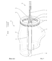
- Fig. 5 shows reference means 25 according to the invention, which reference means 25 have a reference mark 26 in the form of a ring, and holding means 27 which are here formed by two rods.
- Holding means 27 connect reference mark 26 to a holding means head part 28.
- Holding means head part 28 comprises brackets 29 which act as spacers between holding means 27 and a second grip and through which the holding means 27 are guided and, respectively, are secured on holding means head part 28.
- Holding means head part 28 also has a recess 30 via which holding means head part 28 is placed onto shaft 15 of the insertion system.
- holding means head part 28 also has locking means 31 provided at its proximal end, which locking means 31 interact with complementary locking means or recesses on a first grip in such a way that reference means 25 are mounted removably on the insertion system.
- Fig. 6 shows the insertion system 10 with a first grip 33 which has grip furrows 34 and is fixedly connected to shaft 15 and, at its upper end, has a passage 35 for a guide wire (not shown).
- Insertion system 10 is furthermore provided with a second grip 36 which has grip furrows 34, is fixedly connected to sheath 19, and is mounted movably in axial direction relative to shaft 15.
- Insertion system 10 furthermore comprises reference means 25 (shown in Fig. 5 ) in which annular reference mark 26 comprises a recess 32 and in which the holding means 27 are guided outside second grip 36.
- Fig. 7a shows insertion system 10 in which holding means 27 are guided through recesses 37 on second grip 36 in such a way that second grip 36 can be moved in axial direction relative to holding means 27.
- Recesses 37 on second grip 36 serve to release holding means 27 from second grip 36 during removal of reference means 25 from insertion system 10.
- Fig. 7b shows a view of second grip 36 of the embodiment of Fig. 7a , with recesses 37 in which holding means 27 are received, this view being turned through 180° about the longitudinal axis in relation to Fig. 7a .
- Fig. 8a shows, in a view similar to Fig. 3 , another embodiment of insertion system 10, in which annular reference mark 26 comprises an external diameter smaller than the internal diameter of body vessel 11 to be treated.
- reference mark 26 is arranged at the same axial level as deployment zone 21 and is positioned opposite landing zone 20 in the proximal end of a body vessel 11.
- Fig. 8b shows a sectional view of insertion system 10 of Fig. 8a , at the level of the section line I from Fig. 8a .
- reference mark 26 having an internal dimension ⁇ and an external dimension ⁇ , is arranged inside of wall 12 of body vessel 11, having an internal diameter ⁇ and an external diameter ⁇ .
- the internal diameter ⁇ of vessel wall 12, here, is greater than the external dimension ⁇ of reference mark 26.
- Fig. 8c shows a detail of a sectional view of insertion system 10 of Fig. 8a in the axial direction along the section plane II from Fig. 8b .
- reference mark 26 in its axial position marks deployment zone 21.
- the coincidence of the axial position between deployment zone 21 and landing zone 20 is marked by the position of reference mark 26.
- Fig. 8d shows another embodiment of insertion system 10 with reference means 25, in which the reference mark 26 comprises an internal dimension greater than the external diameter of body vessel 11 to be treated.
- reference mark 26 surrounds body vessel 11 at the same axial level as deployment zone 21 and landing zone 20.
- Fig. 8e shows a sectional view of insertion system 10 of Fig. 8d , at the level of the section line III from Fig. 8c .
- reference mark 26 having internal dimension ⁇ and external dimension ⁇ , is arranged outside of wall 12 of body vessel 11, having internal diameter ⁇ and external diameter ⁇ .
- the internal dimension ⁇ of reference mark 26, here, is greater than the external diameter ⁇ of vessel wall 12.
- Fig. 8f shows a third embodiment of the novel insertion system 10 with reference mark 26 and holding means 27, which as a whole are designed in such a way that reference mark 26 is located in axial direction proximal to upper margin 14 of body vessel 11, whereas deployment zone 21 is at the same level as landing zone 20.
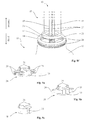
- Fig. 9a shows a first embodiment of holding means head part 28 of the reference means 25 according to the invention, where holding means head part 28 comprises brackets 29 for receiving holding means 27 and acting as spacers between holding means 27 and the second grip 36, recess 30 for releasing the holding means head part 28 from shaft 15, and locking means 31 for securing reference means 25 to first grip 33 in a removable manner.
- Fig. 9b shows a second embodiment of holding means head part 28 of reference means 25 according to the invention, with brackets 29, recess 30 and locking means 31, wherein each of the brackets 29 is formed in one piece.
- Fig. 9c shows a third embodiment of holding means head part 28, which has recess 30 and locking means 31 but has no brackets, such that holding means 27 are received in the interior of holding means head part 28. This reduces the distance between holding means 27 and shaft 15 as compared to the embodiment with brackets (see Fig. 9a for example).
- Fig. 9d shows a fourth embodiment of holding means head part 28, wherein holding means head part 28 is divided into a head part top segment 38 and a head part bottom segment 39, wherein head part bottom segment 39 comprises brackets 29, and head part top segment 38 comprises locking means 31. Moreover, head part top segment 38 and head part bottom segment 39 both comprise recesses 30. Head part top segment 38 is connected to head part bottom segment 39 via a radially encircling holding means 40. Thus, holding means head part 28 can be locked on shaft 15 by turning head part bottom segment 39 relative to head part top segment 38, since recesses 30 then point in different directions.
- Fig. 9e shows a cross section through the fourth embodiment, as shown in Fig. 9d , of holding means head part 28, with head part top segment 38, head part bottom segment 39, brackets 29, locking means 31, radially encircling holding means 40, and recess 30.
- Fig. 9f shows a plan view of the fourth embodiment, as shown in Fig. 9d , of holding means head part 28, showing that brackets 29 are arranged rotatable relative to locking means 31.
- Fig. 9g shows a fifth embodiment of holding means head part 28, in which head part top segment 38 comprises a thread 41 at its proximal portion and comprises a radially encircling knurled surface 42 at its distal portion, and in which head part bottom segment 39 comprises brackets 29, wherein both head part top segment 38 and head part bottom segment 39 comprise a recess 30, and head part top segment 38 is connected to head part bottom segment 39 via said radially encircling holding means 40.
- head part top segment 38 and head part bottom segment 39 can in this case serve to screw reference means 25 onto a suitable complementary thread on or in the first grip by rotating head part top segment 38, while the rest of the reference means 25, including head part bottom segment 39, holding means 27 and reference mark 26, does not have to be entrained in the direction of rotation.
Landscapes
- Health & Medical Sciences (AREA)
- Engineering & Computer Science (AREA)
- Biomedical Technology (AREA)
- Cardiology (AREA)
- Oral & Maxillofacial Surgery (AREA)
- Transplantation (AREA)
- Heart & Thoracic Surgery (AREA)
- Vascular Medicine (AREA)
- Life Sciences & Earth Sciences (AREA)
- Animal Behavior & Ethology (AREA)
- General Health & Medical Sciences (AREA)
- Public Health (AREA)
- Veterinary Medicine (AREA)
- Media Introduction/Drainage Providing Device (AREA)
- Prostheses (AREA)
Applications Claiming Priority (1)
| Application Number | Priority Date | Filing Date | Title |
|---|---|---|---|
| DE102008048533A DE102008048533A1 (de) | 2008-09-16 | 2008-09-16 | Einführsystem zum Absetzen von katheterbasierten Stentvorrichtungen |
Publications (2)
| Publication Number | Publication Date |
|---|---|
| EP2165683A1 true EP2165683A1 (de) | 2010-03-24 |
| EP2165683B1 EP2165683B1 (de) | 2013-11-13 |
Family
ID=41397440
Family Applications (1)
| Application Number | Title | Priority Date | Filing Date |
|---|---|---|---|
| EP09169903.3A Active EP2165683B1 (de) | 2008-09-16 | 2009-09-10 | Einführungssystem zur Anwendung in Katheterstentvorrichtungen |
Country Status (4)
| Country | Link |
|---|---|
| US (1) | US8470015B2 (de) |
| EP (1) | EP2165683B1 (de) |
| DE (1) | DE102008048533A1 (de) |
| ES (1) | ES2440545T3 (de) |
Families Citing this family (4)
| Publication number | Priority date | Publication date | Assignee | Title |
|---|---|---|---|---|
| EP2559401B1 (de) | 2009-12-01 | 2016-05-04 | Altura Medical, Inc. | Modulare Endograft-Vorrichtungen |
| WO2012040240A1 (en) | 2010-09-20 | 2012-03-29 | Altura Medical, Inc. | Stent graft delivery systems and associated methods |
| US10285833B2 (en) | 2012-08-10 | 2019-05-14 | Lombard Medical Limited | Stent delivery systems and associated methods |
| US9737426B2 (en) | 2013-03-15 | 2017-08-22 | Altura Medical, Inc. | Endograft device delivery systems and associated methods |
Citations (5)
| Publication number | Priority date | Publication date | Assignee | Title |
|---|---|---|---|---|
| US6136006A (en) * | 1992-05-08 | 2000-10-24 | Boston Scientific Corporation | Apparatus for deliver and deployment of a stent |
| EP1210959A2 (de) * | 2000-11-29 | 2002-06-05 | Wollschläger, Helmut | Verfahren und Vorrichtung zur Verwendung in nichtinvasiven, chirurgischen Behandlungen |
| US20040138734A1 (en) * | 2001-04-11 | 2004-07-15 | Trivascular, Inc. | Delivery system and method for bifurcated graft |
| US20040176682A1 (en) * | 2003-03-03 | 2004-09-09 | Murphy Kieran P. | Method and apparatus for reducing exposure to an imaging beam |
| EP1943988A1 (de) * | 2007-01-12 | 2008-07-16 | Medtronic Vascular, Inc. | Vorrichtung und Verfahren zum Einsetzen einer Prothese |
Family Cites Families (20)
| Publication number | Priority date | Publication date | Assignee | Title |
|---|---|---|---|---|
| US3628535A (en) * | 1969-11-12 | 1971-12-21 | Nibot Corp | Surgical instrument for implanting a prosthetic heart valve or the like |
| US4411653A (en) | 1982-01-28 | 1983-10-25 | Razi M Dean | Cannula introducer |
| DE9010130U1 (de) | 1989-07-13 | 1990-09-13 | American Medical Systems, Inc., Minnetonka, Minn. | Instrument zum Anbringen eines Aufweitimplantats |
| US5707376A (en) | 1992-08-06 | 1998-01-13 | William Cook Europe A/S | Stent introducer and method of use |
| US5556413A (en) * | 1994-03-11 | 1996-09-17 | Advanced Cardiovascular Systems, Inc. | Coiled stent with locking ends |
| US6165195A (en) | 1997-08-13 | 2000-12-26 | Advanced Cardiovascylar Systems, Inc. | Stent and catheter assembly and method for treating bifurcations |
| US5944727A (en) | 1998-09-02 | 1999-08-31 | Datascope Investment Corp. | Stent/graft catheter handle |
| WO2000018330A1 (en) | 1998-09-30 | 2000-04-06 | Impra, Inc. | Delivery mechanism for implantable stent |
| US6679909B2 (en) * | 2001-07-31 | 2004-01-20 | Advanced Cardiovascular Systems, Inc. | Rapid exchange delivery system for self-expanding stent |
| US7052511B2 (en) | 2002-04-04 | 2006-05-30 | Scimed Life Systems, Inc. | Delivery system and method for deployment of foreshortening endoluminal devices |
| US7105016B2 (en) | 2002-04-23 | 2006-09-12 | Medtronic Vascular, Inc. | Integrated mechanical handle with quick slide mechanism |
| US6892090B2 (en) * | 2002-08-19 | 2005-05-10 | Surgical Navigation Technologies, Inc. | Method and apparatus for virtual endoscopy |
| US6814746B2 (en) * | 2002-11-01 | 2004-11-09 | Ev3 Peripheral, Inc. | Implant delivery system with marker interlock |
| ITTO20030037A1 (it) | 2003-01-24 | 2004-07-25 | Sorin Biomedica Cardio S P A Ora S Orin Biomedica | Dispositivo d'azionamento per cateteri. |
| US6966923B2 (en) | 2003-01-24 | 2005-11-22 | Medtronic Vascular, Inc. | Stent delivery system and low profile stent |
| DE10335649A1 (de) | 2003-07-30 | 2005-02-24 | Jotec Gmbh | Flechtstent zur Implantation in ein Blutgefäß |
| DE102004023559A1 (de) | 2004-02-25 | 2005-09-15 | Schreiber, Hans, Dr. Dr. | Katheter und/oder Stents insbesondere unter Verwendung von Formgedächtniskunststoffen und angepassten Bausatzvorrichtungen bzw. -elementen |
| DE102005059261B4 (de) * | 2005-12-12 | 2013-09-05 | Siemens Aktiengesellschaft | Kathetervorrichtung zur Behandlung eines teilweisen und/oder vollständigen Gefässverschlusses und Röntgeneinrichtung |
| US20080051867A1 (en) * | 2006-08-28 | 2008-02-28 | Davila Luis A | Multiple in vivo implant delivery device |
| US7655034B2 (en) | 2006-11-14 | 2010-02-02 | Medtronic Vascular, Inc. | Stent-graft with anchoring pins |
-
2008
- 2008-09-16 DE DE102008048533A patent/DE102008048533A1/de not_active Withdrawn
-
2009
- 2009-09-10 EP EP09169903.3A patent/EP2165683B1/de active Active
- 2009-09-10 ES ES09169903.3T patent/ES2440545T3/es active Active
- 2009-09-15 US US12/560,302 patent/US8470015B2/en active Active
Patent Citations (5)
| Publication number | Priority date | Publication date | Assignee | Title |
|---|---|---|---|---|
| US6136006A (en) * | 1992-05-08 | 2000-10-24 | Boston Scientific Corporation | Apparatus for deliver and deployment of a stent |
| EP1210959A2 (de) * | 2000-11-29 | 2002-06-05 | Wollschläger, Helmut | Verfahren und Vorrichtung zur Verwendung in nichtinvasiven, chirurgischen Behandlungen |
| US20040138734A1 (en) * | 2001-04-11 | 2004-07-15 | Trivascular, Inc. | Delivery system and method for bifurcated graft |
| US20040176682A1 (en) * | 2003-03-03 | 2004-09-09 | Murphy Kieran P. | Method and apparatus for reducing exposure to an imaging beam |
| EP1943988A1 (de) * | 2007-01-12 | 2008-07-16 | Medtronic Vascular, Inc. | Vorrichtung und Verfahren zum Einsetzen einer Prothese |
Also Published As
| Publication number | Publication date |
|---|---|
| ES2440545T3 (es) | 2014-01-29 |
| US8470015B2 (en) | 2013-06-25 |
| EP2165683B1 (de) | 2013-11-13 |
| DE102008048533A1 (de) | 2010-03-25 |
| US20100070017A1 (en) | 2010-03-18 |
Similar Documents
| Publication | Publication Date | Title |
|---|---|---|
| US10194905B2 (en) | Devices, systems, and methods for endovascular staple and/or prosthesis delivery and implantation | |
| CN109561958B (zh) | 血管医疗装置和系统 | |
| JP4570957B2 (ja) | 医療器具送達装置 | |
| CA2487131C (en) | Thoracic stent graft introducer | |
| US9095464B2 (en) | Slotted pusher rod for flexible delivery system | |
| US20090112302A1 (en) | Devices, systems, and methods for endovascular staple and/or prosthesis delivery and implantation | |
| US20090138072A1 (en) | Devices, systems, and methods for endovascular staple and/or prosthesis delivery and implantation | |
| JP2022515988A (ja) | 統合されたイメージング及び医療デバイスの配送装置及び使用方法 | |
| CN107106312B (zh) | 支架递送装置 | |
| CA2740831A1 (en) | Devices, systems, and methods for endovascular staple and/or prosthesis delivery and implantation | |
| JPH11503056A (ja) | 血管内測定装置ならびに導入配置手段 | |
| AU2006305689A1 (en) | Devices, systems, and methods for prosthesis delivery and implantation, including the use of a fastener tool | |
| JP6505771B2 (ja) | 血管内グラフト給送装置 | |
| CN113967115A (zh) | 一种支架及支架递送系统 | |
| EP2165683B1 (de) | Einführungssystem zur Anwendung in Katheterstentvorrichtungen | |
| EP3265163B1 (de) | Führungsdraht mit mehrlumigem zugangsgewinden | |
| US12245939B2 (en) | Methods and devices for deployment of a transcatheter heart valve | |
| CN222566031U (zh) | 一种内脏动脉原位开窗定位机构 | |
| US8021374B2 (en) | Method and device for the controlled delivery and placement of securing elements in a body | |
| CN116710030A (zh) | 套筒回拉机构 |
Legal Events
| Date | Code | Title | Description |
|---|---|---|---|
| PUAI | Public reference made under article 153(3) epc to a published international application that has entered the european phase |
Free format text: ORIGINAL CODE: 0009012 |
|
| AK | Designated contracting states |
Kind code of ref document: A1 Designated state(s): AT BE BG CH CY CZ DE DK EE ES FI FR GB GR HR HU IE IS IT LI LT LU LV MC MK MT NL NO PL PT RO SE SI SK SM TR |
|
| AX | Request for extension of the european patent |
Extension state: AL BA RS |
|
| 17P | Request for examination filed |
Effective date: 20100702 |
|
| 17Q | First examination report despatched |
Effective date: 20101005 |
|
| REG | Reference to a national code |
Ref country code: DE Ref legal event code: R079 Ref document number: 602009020052 Country of ref document: DE Free format text: PREVIOUS MAIN CLASS: A61F0002840000 Ipc: A61F0002966000 |
|
| RIC1 | Information provided on ipc code assigned before grant |
Ipc: A61F 2/966 20130101AFI20130402BHEP |
|
| GRAP | Despatch of communication of intention to grant a patent |
Free format text: ORIGINAL CODE: EPIDOSNIGR1 |
|
| INTG | Intention to grant announced |
Effective date: 20130531 |
|
| GRAS | Grant fee paid |
Free format text: ORIGINAL CODE: EPIDOSNIGR3 |
|
| GRAA | (expected) grant |
Free format text: ORIGINAL CODE: 0009210 |
|
| AK | Designated contracting states |
Kind code of ref document: B1 Designated state(s): AT BE BG CH CY CZ DE DK EE ES FI FR GB GR HR HU IE IS IT LI LT LU LV MC MK MT NL NO PL PT RO SE SI SK SM TR |
|
| REG | Reference to a national code |
Ref country code: GB Ref legal event code: FG4D |
|
| REG | Reference to a national code |
Ref country code: CH Ref legal event code: EP |
|
| REG | Reference to a national code |
Ref country code: AT Ref legal event code: REF Ref document number: 640236 Country of ref document: AT Kind code of ref document: T Effective date: 20131215 |
|
| REG | Reference to a national code |
Ref country code: IE Ref legal event code: FG4D |
|
| REG | Reference to a national code |
Ref country code: DE Ref legal event code: R096 Ref document number: 602009020052 Country of ref document: DE Effective date: 20140109 |
|
| REG | Reference to a national code |
Ref country code: ES Ref legal event code: FG2A Ref document number: 2440545 Country of ref document: ES Kind code of ref document: T3 Effective date: 20140129 |
|
| REG | Reference to a national code |
Ref country code: NL Ref legal event code: VDEP Effective date: 20131113 |
|
| REG | Reference to a national code |
Ref country code: AT Ref legal event code: MK05 Ref document number: 640236 Country of ref document: AT Kind code of ref document: T Effective date: 20131113 |
|
| REG | Reference to a national code |
Ref country code: LT Ref legal event code: MG4D |
|
| PG25 | Lapsed in a contracting state [announced via postgrant information from national office to epo] |
Ref country code: IS Free format text: LAPSE BECAUSE OF FAILURE TO SUBMIT A TRANSLATION OF THE DESCRIPTION OR TO PAY THE FEE WITHIN THE PRESCRIBED TIME-LIMIT Effective date: 20140313 Ref country code: HR Free format text: LAPSE BECAUSE OF FAILURE TO SUBMIT A TRANSLATION OF THE DESCRIPTION OR TO PAY THE FEE WITHIN THE PRESCRIBED TIME-LIMIT Effective date: 20131113 Ref country code: FI Free format text: LAPSE BECAUSE OF FAILURE TO SUBMIT A TRANSLATION OF THE DESCRIPTION OR TO PAY THE FEE WITHIN THE PRESCRIBED TIME-LIMIT Effective date: 20131113 Ref country code: NL Free format text: LAPSE BECAUSE OF FAILURE TO SUBMIT A TRANSLATION OF THE DESCRIPTION OR TO PAY THE FEE WITHIN THE PRESCRIBED TIME-LIMIT Effective date: 20131113 Ref country code: SE Free format text: LAPSE BECAUSE OF FAILURE TO SUBMIT A TRANSLATION OF THE DESCRIPTION OR TO PAY THE FEE WITHIN THE PRESCRIBED TIME-LIMIT Effective date: 20131113 Ref country code: NO Free format text: LAPSE BECAUSE OF FAILURE TO SUBMIT A TRANSLATION OF THE DESCRIPTION OR TO PAY THE FEE WITHIN THE PRESCRIBED TIME-LIMIT Effective date: 20140213 Ref country code: LT Free format text: LAPSE BECAUSE OF FAILURE TO SUBMIT A TRANSLATION OF THE DESCRIPTION OR TO PAY THE FEE WITHIN THE PRESCRIBED TIME-LIMIT Effective date: 20131113 |
|
| PG25 | Lapsed in a contracting state [announced via postgrant information from national office to epo] |
Ref country code: BE Free format text: LAPSE BECAUSE OF FAILURE TO SUBMIT A TRANSLATION OF THE DESCRIPTION OR TO PAY THE FEE WITHIN THE PRESCRIBED TIME-LIMIT Effective date: 20131113 Ref country code: AT Free format text: LAPSE BECAUSE OF FAILURE TO SUBMIT A TRANSLATION OF THE DESCRIPTION OR TO PAY THE FEE WITHIN THE PRESCRIBED TIME-LIMIT Effective date: 20131113 Ref country code: LV Free format text: LAPSE BECAUSE OF FAILURE TO SUBMIT A TRANSLATION OF THE DESCRIPTION OR TO PAY THE FEE WITHIN THE PRESCRIBED TIME-LIMIT Effective date: 20131113 Ref country code: CY Free format text: LAPSE BECAUSE OF FAILURE TO SUBMIT A TRANSLATION OF THE DESCRIPTION OR TO PAY THE FEE WITHIN THE PRESCRIBED TIME-LIMIT Effective date: 20131113 |
|
| PG25 | Lapsed in a contracting state [announced via postgrant information from national office to epo] |
Ref country code: PT Free format text: LAPSE BECAUSE OF FAILURE TO SUBMIT A TRANSLATION OF THE DESCRIPTION OR TO PAY THE FEE WITHIN THE PRESCRIBED TIME-LIMIT Effective date: 20140313 |
|
| PG25 | Lapsed in a contracting state [announced via postgrant information from national office to epo] |
Ref country code: EE Free format text: LAPSE BECAUSE OF FAILURE TO SUBMIT A TRANSLATION OF THE DESCRIPTION OR TO PAY THE FEE WITHIN THE PRESCRIBED TIME-LIMIT Effective date: 20131113 |
|
| REG | Reference to a national code |
Ref country code: DE Ref legal event code: R097 Ref document number: 602009020052 Country of ref document: DE |
|
| PG25 | Lapsed in a contracting state [announced via postgrant information from national office to epo] |
Ref country code: PL Free format text: LAPSE BECAUSE OF FAILURE TO SUBMIT A TRANSLATION OF THE DESCRIPTION OR TO PAY THE FEE WITHIN THE PRESCRIBED TIME-LIMIT Effective date: 20131113 Ref country code: SK Free format text: LAPSE BECAUSE OF FAILURE TO SUBMIT A TRANSLATION OF THE DESCRIPTION OR TO PAY THE FEE WITHIN THE PRESCRIBED TIME-LIMIT Effective date: 20131113 Ref country code: CZ Free format text: LAPSE BECAUSE OF FAILURE TO SUBMIT A TRANSLATION OF THE DESCRIPTION OR TO PAY THE FEE WITHIN THE PRESCRIBED TIME-LIMIT Effective date: 20131113 Ref country code: RO Free format text: LAPSE BECAUSE OF FAILURE TO SUBMIT A TRANSLATION OF THE DESCRIPTION OR TO PAY THE FEE WITHIN THE PRESCRIBED TIME-LIMIT Effective date: 20131113 |
|
| PLBE | No opposition filed within time limit |
Free format text: ORIGINAL CODE: 0009261 |
|
| STAA | Information on the status of an ep patent application or granted ep patent |
Free format text: STATUS: NO OPPOSITION FILED WITHIN TIME LIMIT |
|
| PG25 | Lapsed in a contracting state [announced via postgrant information from national office to epo] |
Ref country code: DK Free format text: LAPSE BECAUSE OF FAILURE TO SUBMIT A TRANSLATION OF THE DESCRIPTION OR TO PAY THE FEE WITHIN THE PRESCRIBED TIME-LIMIT Effective date: 20131113 |
|
| 26N | No opposition filed |
Effective date: 20140814 |
|
| REG | Reference to a national code |
Ref country code: DE Ref legal event code: R097 Ref document number: 602009020052 Country of ref document: DE Effective date: 20140814 |
|
| PG25 | Lapsed in a contracting state [announced via postgrant information from national office to epo] |
Ref country code: SI Free format text: LAPSE BECAUSE OF FAILURE TO SUBMIT A TRANSLATION OF THE DESCRIPTION OR TO PAY THE FEE WITHIN THE PRESCRIBED TIME-LIMIT Effective date: 20131113 |
|
| PG25 | Lapsed in a contracting state [announced via postgrant information from national office to epo] |
Ref country code: LU Free format text: LAPSE BECAUSE OF FAILURE TO SUBMIT A TRANSLATION OF THE DESCRIPTION OR TO PAY THE FEE WITHIN THE PRESCRIBED TIME-LIMIT Effective date: 20140910 Ref country code: MC Free format text: LAPSE BECAUSE OF FAILURE TO SUBMIT A TRANSLATION OF THE DESCRIPTION OR TO PAY THE FEE WITHIN THE PRESCRIBED TIME-LIMIT Effective date: 20131113 |
|
| REG | Reference to a national code |
Ref country code: CH Ref legal event code: PL |
|
| REG | Reference to a national code |
Ref country code: IE Ref legal event code: MM4A |
|
| PG25 | Lapsed in a contracting state [announced via postgrant information from national office to epo] |
Ref country code: CH Free format text: LAPSE BECAUSE OF NON-PAYMENT OF DUE FEES Effective date: 20140930 Ref country code: LI Free format text: LAPSE BECAUSE OF NON-PAYMENT OF DUE FEES Effective date: 20140930 |
|
| PG25 | Lapsed in a contracting state [announced via postgrant information from national office to epo] |
Ref country code: IE Free format text: LAPSE BECAUSE OF NON-PAYMENT OF DUE FEES Effective date: 20140910 |
|
| PG25 | Lapsed in a contracting state [announced via postgrant information from national office to epo] |
Ref country code: SM Free format text: LAPSE BECAUSE OF FAILURE TO SUBMIT A TRANSLATION OF THE DESCRIPTION OR TO PAY THE FEE WITHIN THE PRESCRIBED TIME-LIMIT Effective date: 20131113 |
|
| PG25 | Lapsed in a contracting state [announced via postgrant information from national office to epo] |
Ref country code: BG Free format text: LAPSE BECAUSE OF FAILURE TO SUBMIT A TRANSLATION OF THE DESCRIPTION OR TO PAY THE FEE WITHIN THE PRESCRIBED TIME-LIMIT Effective date: 20131113 Ref country code: GR Free format text: LAPSE BECAUSE OF FAILURE TO SUBMIT A TRANSLATION OF THE DESCRIPTION OR TO PAY THE FEE WITHIN THE PRESCRIBED TIME-LIMIT Effective date: 20140214 Ref country code: MT Free format text: LAPSE BECAUSE OF FAILURE TO SUBMIT A TRANSLATION OF THE DESCRIPTION OR TO PAY THE FEE WITHIN THE PRESCRIBED TIME-LIMIT Effective date: 20131113 |
|
| PG25 | Lapsed in a contracting state [announced via postgrant information from national office to epo] |
Ref country code: HU Free format text: LAPSE BECAUSE OF FAILURE TO SUBMIT A TRANSLATION OF THE DESCRIPTION OR TO PAY THE FEE WITHIN THE PRESCRIBED TIME-LIMIT; INVALID AB INITIO Effective date: 20090910 Ref country code: TR Free format text: LAPSE BECAUSE OF FAILURE TO SUBMIT A TRANSLATION OF THE DESCRIPTION OR TO PAY THE FEE WITHIN THE PRESCRIBED TIME-LIMIT Effective date: 20131113 |
|
| REG | Reference to a national code |
Ref country code: FR Ref legal event code: PLFP Year of fee payment: 8 |
|
| REG | Reference to a national code |
Ref country code: FR Ref legal event code: PLFP Year of fee payment: 9 |
|
| PG25 | Lapsed in a contracting state [announced via postgrant information from national office to epo] |
Ref country code: MK Free format text: LAPSE BECAUSE OF FAILURE TO SUBMIT A TRANSLATION OF THE DESCRIPTION OR TO PAY THE FEE WITHIN THE PRESCRIBED TIME-LIMIT Effective date: 20131113 |
|
| REG | Reference to a national code |
Ref country code: FR Ref legal event code: PLFP Year of fee payment: 10 |
|
| P01 | Opt-out of the competence of the unified patent court (upc) registered |
Effective date: 20230530 |
|
| PGFP | Annual fee paid to national office [announced via postgrant information from national office to epo] |
Ref country code: DE Payment date: 20250924 Year of fee payment: 17 |
|
| PGFP | Annual fee paid to national office [announced via postgrant information from national office to epo] |
Ref country code: IT Payment date: 20250923 Year of fee payment: 17 |
|
| PGFP | Annual fee paid to national office [announced via postgrant information from national office to epo] |
Ref country code: GB Payment date: 20250918 Year of fee payment: 17 |
|
| PGFP | Annual fee paid to national office [announced via postgrant information from national office to epo] |
Ref country code: FR Payment date: 20250919 Year of fee payment: 17 |
|
| PGFP | Annual fee paid to national office [announced via postgrant information from national office to epo] |
Ref country code: ES Payment date: 20251028 Year of fee payment: 17 |