EP2166159A2 - Réseau de canalisations d'eau potable pour la préservation de la qualité de l'eau potable et procédé d'opération d'un tel réseau - Google Patents
Réseau de canalisations d'eau potable pour la préservation de la qualité de l'eau potable et procédé d'opération d'un tel réseau Download PDFInfo
- Publication number
- EP2166159A2 EP2166159A2 EP09170586A EP09170586A EP2166159A2 EP 2166159 A2 EP2166159 A2 EP 2166159A2 EP 09170586 A EP09170586 A EP 09170586A EP 09170586 A EP09170586 A EP 09170586A EP 2166159 A2 EP2166159 A2 EP 2166159A2
- Authority
- EP
- European Patent Office
- Prior art keywords
- drinking water
- line
- toilet
- valve
- flushing
- Prior art date
- Legal status (The legal status is an assumption and is not a legal conclusion. Google has not performed a legal analysis and makes no representation as to the accuracy of the status listed.)
- Granted
Links
Images

Classifications
-
- E—FIXED CONSTRUCTIONS
- E03—WATER SUPPLY; SEWERAGE
- E03B—INSTALLATIONS OR METHODS FOR OBTAINING, COLLECTING, OR DISTRIBUTING WATER
- E03B7/00—Water main or service pipe systems
- E03B7/07—Arrangement of devices, e.g. filters, flow controls, measuring devices, siphons or valves, in the pipe systems
- E03B7/08—Arrangement of draining devices, e.g. manual shut-off valves
Definitions
- the invention relates to a drinking water pipe system with at least one cold water line, which is designed in the form of a series line or ring line and has at least one serving as a sampling tap nozzle and an outlet, wherein the outlet is connected to a cistern or a toilet or Urinal Albanyung triggering valve is arranged and wherein in one embodiment of the cold water line is arranged as a series line cistern or a toilet or urinal flush valve triggering at the end of the cold water line or in a design of the cold water line as a ring line cistern or a toilet or urinal flush valve in a the middle of the Ring line comprehensive range, which extends over a line length of 30%, preferably 20% of the loop length is arranged. Furthermore, the invention relates to a method for operating such a drinking water pipe system.
- a drinking water system which has at least one floor or riser pipe and several in the extension direction of the strand arranged one behind the other and each leading to a withdrawal point ring lines.
- the branch or the mouth of the respective loop on the strand are designed such that in a drinking water removal at a connected to the strand sampling point by a flow in the strand between the branch and the mouth upstream in the flow direction of the sampling ring loops of the strand Pressure difference is generated by which in the or the upstream ring lines a purge flow is generated.
- Each ring line opens for this purpose in a on the strand in the manner of a throttle (nozzle) trained Ring effets Surprisearmatur. This throttle causes additional pressure loss in the associated drinking water system (overall system).
- the Ring eins Stellertur requires the desired Spülströmung a minimum flow rate, which is in larger drinking water systems, such as those of hotels, where many water tapping points are often not used for a long period of time, sometimes only achieved when the nozzles in the few occupied rooms for a relatively long time full be opened, which however hardly corresponds to the usual user habits.
- the present invention has for its object to provide a drinking water pipe system or a method for operating a drinking water pipe system, which provides a high level of security for the maintenance of the required drinking water hygiene and does not cause unnecessarily high water consumption.
- the drinking water supply system comprises at least one cold water line, which is designed in the form of a series line or loop and at least one serving as a sampling point dispensing valve and outlet has connected to the outlet cistern or a toilet or Urinal Albanyung triggering valve is arranged, and wherein in an embodiment of the cold water line as a series line cistern or a toilet or urinal flushing valve is disposed at the end of the cold water line or in a design of the cold water line as a ring line cistern or a toilet or urinal flushing valve in a center of the loop comprehensive Range, which extends over a line length of 30%, preferably 20% of the loop length, is arranged.
- the dispensing valve may be, for example, an outlet fitting of a washstand, a bathtub, a shower or a bidet.
- an electronic control which is provided with a time measuring device and detected by a sensor drinking water removal from the cold water line, the sensor activates the time measuring device in a drinking water removal from the cold water line, and wherein the electronic control when exceeding a predetermined or predeterminable time interval since the last drinking water removal the valve or an actuator to trigger a toilet or urinal flushing.
- the inventive method for operating a drinking water supply system of the type mentioned is essentially characterized in that a drinking water extraction from the cold water line is detected by a sensor, wherein in a drinking water extraction from the cold water line by a signal emitted by the sensor, a time measuring device is activated, and if the valve or an actuating device for triggering a toilet or urinal flushing is actuated when a predetermined or predefinable time interval has been exceeded since the last withdrawal of drinking water from the cold water line.
- the solution according to the invention avoids critical water stagnation by ensuring the intended operation of the drinking water pipeline system over any length of time periods, i.
- the drinking water withdrawals are essentially as planned according to the original design.
- the intended operation is ensured by the electronic control (including the sensor and the time measuring device) with time-based and demand-controlled flushing, wherein the electronic control can be arranged decentralized.
- the invention is based on the recognition that in a cold water line of a drinking water system with at least one tapping point, for example a washbasin inlet fitting, and a valve for triggering a toilet or urinal flushing, usually with each toilet or urinal flush Sufficient rinsing of the cold water strand takes place, so that no too long water stagnation occurs with the risk of a critically important germ multiplication, when the cistern or the valve, viewed downstream of the tapping point, is arranged at the end of the cold water strand. It has a favorable effect on the maintenance of drinking water quality in the cold water pipe that toilet or Urinal Albany are usually triggered several times a day or week and with each rinse a relatively large volume of water of the cold water strand is replaced.
- the solution according to the invention detects a lack of drinking water and the intended operation, i. a proper rinsing ensured to avoid stagnation caused by microbial contamination.
- the time interval after the electronic control override controls the actuator or the valve to trigger a toilet or urinal flush can be set or adjusted so that always in good time before a time from a lack of drinking water removal with a critical health germ multiplication the cold water line is to be expected, a corresponding control and thus a water exchange takes place in the cold water line.
- the invention thus proposes that a rinse at too long a period lack of drinking water takes place according to freely parameterizable time windows.
- the solution according to the invention basically does not require a loop to maintain drinking water quality and thus offers a corresponding material cost and installation cost advantage over solutions based on the installation of ring lines.
- one or more ring lines can be provided in a drinking water pipe system according to the invention.
- the sensor for detecting a drinking water removal or a lack of drinking water from the cold water line can be arranged at different points of the cold water line.
- the sensor can be arranged on the dispensing valve and / or be integrated in the same. It is particularly within the scope of the invention that the drinking water removal or lack of drinking water withdrawal is indirectly monitored by the sensor detects a position and / or movement of a valve body of the dispensing valve.
- a further preferred embodiment of the drinking water supply system according to the invention is that a flow or volume flow meter is used as a sensor for detecting a drinking water removal or a lack of drinking water removal from the cold water line.
- the sensor can be attached to the same or integrated in the same at the end of the cold water strand, but also at the beginning of the cold water strand.
- a release of a toilet or urinal flush by means of the sensor is detected as drinking water removal from the cold water line.
- the senor is preferably integrated in an actuating plate serving to trigger the toilet or urinal flushing.
- the sensor may also be arranged / integrated in a water inlet valve of the toilet or urinal and / or in a cistern associated with the toilet or urinal.
- a further preferred embodiment of the drinking water supply system provides that the electronic control is arranged in and / or on a toilet or Urinal Fashionkasten. This also simplifies the assembly of system components on site.
- a further preferred embodiment of the invention provides that the electronic control comprises an adjustable timer, with which the duration of the activation of the actuating device or the opening duration of the valve (purge valve) can be predetermined.
- the amount of flushing water required to avoid a critical water stagnation can be optimally adapted to the length or the line volume of the relevant cold water line, so that only as much water is exchanged during the flushing of the cold water line as to avoid a health risk critical microbial contamination is required.
- the water volume to be exchanged in the absence of drinking water removal can be set smaller than the volume of water consumed, for example, in the case of a toilet flush triggered by a user. However, it can be set larger if necessary.
- the volume of water is flexibly adjustable, wherein the adjustment of the volume of water to be exchanged preferably takes place as a function of the electronically monitored drinking water removal.
- Another preferred embodiment of the drinking water supply system is that the electronic control with an input device for setting a desired rinse water volume flow measurement device for determining the dispensed during a toilet or urinal flushing water actual amount and a comparator, the dispensed rinse water actual amount the rinse water setpoint is compared, is provided, the comparator on reaching or exceeding the target rinse water through the actual amount of rinse water emits a signal to the electronic control, so that the latter deactivates the valve (flush valve) or the actuator.
- This refinement also makes it possible to optimally set the rinsing water volume necessary for avoiding microbial contamination in the wiring harness, so that no unnecessarily increased water consumption takes place.
- the electronic control with a data memory for storing time data of the respective Drinking water collection and provided by drinking water dispensing volume data.
- This embodiment enables a comfortable collection of the named data for evaluation purposes, in particular for determining a suitable time interval to be predetermined (time window) for triggering the flushing valve in the absence of drinking water removal and / or for determining the above-mentioned desired flushing water quantity.
- a further advantageous embodiment of the invention provides that the electronic control is provided with a processor, wherein in the processor and / or in the data memory, a statistical function for determining the temporal distribution of drinking water withdrawals from the cold water line is programmed.
- a statistical function for determining the temporal distribution of drinking water withdrawals from the cold water line is programmed.
- the electronic control can also have an interface via which it can be connected to a central building control system and / or a data transmission system, in particular a BUS system.
- the drinking water supply system according to the invention is thus characterized by the following advantages: When used, there is no unnecessarily increased water consumption.
- the intended flushing takes place according to freely programmable time windows and corresponds exclusively to the necessary volume of the installation section to be flushed.
- the system does not require a loop and can also be used in conjunction with apartment water meters.
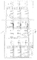
- Fig. 1 is a drinking water system (drinking water installation system) for a multi-storey building 1 with a variety of bathrooms or wet rooms 2.1, 2.2 ... 2.n shown.
- the building 1 may be, for example, a larger residential unit, a hotel, a hospital or a nursing home.
- the drinking water supply system has a transfer point (house connection) 3, via which the drinking water supply system to a drinking water supply network or a Drinking water source is connected.
- the transfer point 3 comprises a water meter, several shut-off valves and a water filter, which is provided with a device for adjusting the water pressure (operating pressure).
- the drinking water line extends to a T-shaped connecting piece, of which a branch to a heating device 4, e.g. a gas-fired boiler with attached hot water storage tank leads to which a several branches comprehensive hot water line 5 and a similarly branched return line (hot water circulation line) 6 is connected.
- a cold water pipe 7 is connected, which is branched into several strand sections.
- the hot water pipe 5, the hot water circulation pipe 6 and the cold water pipe 7 are partially parallel to each other. They form so far parallel floor and riser strands.
- a cold water line 7.1, 7.2 ... 7.n and a hot water line 5.1, 5.2 ... 5.n, respectively are provided with a shut-off valve 8, 9.
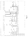
- the cold water pipe 7.1, 7.2 ... 7.n assigned to the respective wet cell 2.1, 2.2... 2.n is in each case designed in the form of a series pipe (cf. Fig. 2 ).
- the respective wet cell 2.1, 2.2 ... 2.n associated hot water line 5.1, 5.2 ... 5.n executed in the form of a series line, ie the extraction points 10.1, 10.2, 10.3 of the respective wet cell 2.1, 2.2 ...
- hot water 5.1 leads first to the fitting connection of a washstand 11, from where he is guided over the fitting connection of a bathtub 12 to the fitting connection of a shower 13.
- This wiring is beneficial for drinking water hygiene, since the shower 13 is usually used more often than the bath 12, and because when showering usually more hot water is consumed than when using the basin mixer 10.1.
- the hot water 5.1 is also the cold water 7.1 of the wet cell 2.1 of the washbasin fitting 10.1 on the bathtub fitting 10.2 led to shower fitting 10.3;
- a toilet 24 is connected or arranged a valve for triggering a toilet flush.
- the valve is provided with an electric lifting unit or designed as an electromagnetically actuated valve.
- the cold water line 7.1 of the wet cell is provided with an electronic control 15 via a sensor (not shown) a drinking water removal from the Cold water line 7.1 recorded.
- the sensor detects a release of a toilet flush as drinking water.
- an integrated in the electronic control 15 time measuring device (not shown) is activated.
- the signal transmission takes place via a signal or control line.
- the electronic control 15 When a predetermined or variably predeterminable time interval is exceeded since the last drinking water removal, the electronic control 15 then controls the valve arranged in the cistern 14 or an actuating device 16, 17 associated with the cistern 14 for triggering a flushing process. Thus, bidirectional communication takes place between the electronic control 15 and the flushing device defined by the cistern 14 or the valve.
- the actuator associated with the cistern 14 is preferably an electrical actuator, e.g. in the form of a push-button 16 and / or an electric lifting unit 18.
- the cistern 14 may also be equipped with a mechanical actuator 17 for triggering a toilet flush.
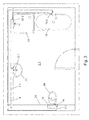
- FIGS. 1 to 3 indicated concealed cistern can eg as in 4 or FIG. 5 be executed.
- the toilet flushing can be triggered via an electric push-button 16.
- a low-voltage lifting unit 18 is arranged, which is connected via a power cable 19 with a 230V transformer 20, which can be accommodated, for example, in the concealed cistern 14 receiving pretext 21.
- the electronic control 15 is arranged in the cistern next to the low-voltage lifting unit 18 and the above-mentioned electronic control 15 in the cistern next to the low-voltage lifting unit 18 and the above-mentioned electronic control 15 is arranged.
- a wireless triggering of the toilet flushing operation by transmitting a radio signal is possible.
- a provided with a low-voltage battery or a corresponding battery radio signal transmitter 22 is used.
- the electronic control 15 is arranged, which is provided with said sensor, the time measuring device and a radio signal receiving unit. The rinsing process can also be triggered via the actuator plate 17 in this embodiment.
- the electronic control 15 has an adjustable timer with which the duration of the activation of the lifting unit 18 or the opening duration of the valve (flushing valve / Spülkastenventils) can be specified.
- the electronic control 15 comprises an input device 23, for example in the form of a remote control for setting a desired rinse water volume, a volumetric flow meter for determining the actual amount of flushing water dispensed during a toilet flushing operation, and a comparator which records the dispensed rinse water actual quantity compared with the desired rinse water volume. Upon reaching or exceeding the desired amount of flushing water through the actual amount of flushing water, the comparator sends a signal to the electronic control 15, whereupon the controller 15 closes the valve or deactivates the actuating device (eg, the lifting unit 18).
- the actuating device eg, the lifting unit 18
- the electronic controller 15 is preferably provided with a data memory and a processor.
- the data memory is used to store time data on drinking water taken as well as drinking water dispensing volume data.
- a statistical function is programmed with which the temporal distribution of drinking water withdrawals from the cold water line 7.1 can be determined or is determined automatically. By means of this integrated statistics function, all important purging parameters of the drinking water supply system are evaluated and, if necessary, the time interval for the automatic triggering of a rinsing process to avoid microbial contamination of the drinking water line is adjusted accordingly.
- the drinking water supply system according to the invention can be advantageously realized in particular in wet rooms or washrooms of hospitals, nursing homes and nursing homes, medical practices, hotels, schools, gymnasiums, barracks and larger dormitories.
- a cistern 14, a urinal flush or a Speller be installed decentralized in the wet room 2.1, 2.2 ... 2.n each hotel room, the respective cistern 14 and the respective urinal flush or Speller with the said electronic control 15, the associated sensor for detecting a drinking water removal and the time measuring device is provided.
- the drinking water supply system according to the invention, a periodic flushing of the cold water line 7.1, 7.2... 7.n is ensured when the hotel room is not occupied. If, however, the wet cell 2.1, 2.2... 2.n of the hotel room is used and drinking water is taken from one of the extraction points 10.1, 10.2, 10.3, then the automatic flushing according to the invention is dispensed with until no too long stagnation time is detected.
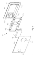
- actuating device 17 comprises a revision opening defining mounting frame 17.1.
- a frame-shaped bracket 17.2 can be used in the mounting frame 17.1 .
- the bracket 17.2 has a plurality of latching elements 17.3, which are associated with recesses 17.4 formed in the mounting frame 17.1, so that the bracket 17.2 can be releasably secured to the mounting frame 17.1.
- the bracket 17.2 carries on its front side an actuating plate 17.5, which is preferably made of glass or plastic and is provided with sensitive key switches 17.6, 17.7 for triggering a full or partial flush.
- the key switches can be glued, for example, on the back of the actuator plate 17.5.
- an electronic control 15 is received, which may be attached to the bracket 17.2 or the actuator plate 17.5.
- the controller 15 of Fig. 6 corresponds to the above with respect to the FIGS. 4 and 5 described controller 15.
- the wet cell 2.1, 2.2 ... 2.n except possibly with the sanitary objects 11, 12, 13 and 24 shown in the embodiment may also be equipped with a urinal.
- the sensor may optionally detect a Urinal Vietnamesevorgang and / or trigger the electronic control 15 Urinal Vietnamesevorgang time and demand controlled to avoid too long water stagnation and thus a critical germ multiplication in the cold water line 7.1, 7.2 ... 7.n.
Landscapes
- Health & Medical Sciences (AREA)
- Life Sciences & Earth Sciences (AREA)
- Engineering & Computer Science (AREA)
- Hydrology & Water Resources (AREA)
- Public Health (AREA)
- Water Supply & Treatment (AREA)
- Sanitary Device For Flush Toilet (AREA)
Priority Applications (1)
| Application Number | Priority Date | Filing Date | Title |
|---|---|---|---|
| PL09170586T PL2166159T3 (pl) | 2008-09-18 | 2009-09-17 | System wodociągowy wody użytkowej do zachowania jakości wody użytkowej oraz sposób sterowania działaniem takiego systemu wodociągowego wody użytkowej |
Applications Claiming Priority (1)
| Application Number | Priority Date | Filing Date | Title |
|---|---|---|---|
| DE102008047938A DE102008047938A1 (de) | 2008-09-18 | 2008-09-18 | Trinkwasserleitungssystem zur Erhaltung der Trinkwassergüte und Verfahren zum Betrieb eines solchen Trinkwasserleitungssystems |
Publications (3)
| Publication Number | Publication Date |
|---|---|
| EP2166159A2 true EP2166159A2 (fr) | 2010-03-24 |
| EP2166159A3 EP2166159A3 (fr) | 2012-12-19 |
| EP2166159B1 EP2166159B1 (fr) | 2015-12-23 |
Family
ID=41402372
Family Applications (1)
| Application Number | Title | Priority Date | Filing Date |
|---|---|---|---|
| EP09170586.3A Active EP2166159B1 (fr) | 2008-09-18 | 2009-09-17 | Réseau de canalisations d'eau potable pour la préservation de la qualité de l'eau potable et procédé d'opération d'un tel réseau |
Country Status (4)
| Country | Link |
|---|---|
| EP (1) | EP2166159B1 (fr) |
| DE (1) | DE102008047938A1 (fr) |
| DK (1) | DK2166159T3 (fr) |
| PL (1) | PL2166159T3 (fr) |
Cited By (7)
| Publication number | Priority date | Publication date | Assignee | Title |
|---|---|---|---|---|
| EP2466019A3 (fr) * | 2010-12-20 | 2014-11-19 | Honeywell Technologies Sarl | Système d'alimentation en eau potable d'un bâtiment, procédé de fonctionnement de celui-ci et dispositif de commande de celui-ci |
| EP3147577A1 (fr) | 2015-09-23 | 2017-03-29 | Stn B.V. | Dispositif et procédé de surveillance d'un écoulement de fluide |
| EP3214230A1 (fr) * | 2016-03-03 | 2017-09-06 | Uponor Innovation AB | Système et procédé de rinçage d'une installation d'eau potable |
| EP3321594A1 (fr) * | 2016-11-11 | 2018-05-16 | Gebr. Kemper GmbH + Co. KG Metallwerke | Système d'eau pourvu d'un chauffe-eau instantané et d'une station de rinçage |
| EP3315673A3 (fr) * | 2016-10-04 | 2018-07-11 | Schell GmbH & Co. KG | Dispositif permettant d'effectuer le rinçage de conduites d'une installation d'eau d'un bâtiment |
| EP3604698A1 (fr) * | 2018-08-01 | 2020-02-05 | ABA Beul GmbH | Procédé et système de rinçage permettant de rincer des réseaux d'alimentation en eau |
| EP3992378A1 (fr) * | 2020-10-29 | 2022-05-04 | Geberit International AG | Chasse d'eau à déclenchement mécanique et électrique |
Families Citing this family (7)
| Publication number | Priority date | Publication date | Assignee | Title |
|---|---|---|---|---|
| DE202011004387U1 (de) * | 2011-03-24 | 2012-06-26 | Viega Gmbh & Co. Kg | Sanitär- oder Heizungsanlage mit mindestens einer elektronisch steuerbaren Armatur |
| DE202012103128U1 (de) * | 2012-08-20 | 2013-11-22 | Hans Sasserath & Co. Kg | Anordnung zur Durchführung einer Hygienespülung in einer Wasserinstallation |
| DE102013015014A1 (de) | 2013-09-07 | 2015-03-12 | Gerd Haberland | Warmwasservorhaltung in Warmwasserversorgungsanlagen nach einer Zähleinrichtung |
| DE202014007233U1 (de) * | 2014-09-04 | 2015-12-09 | Gebr. Kemper Gmbh + Co. Kg Metallwerke | Steuervorrichtung und Trink- und/oder Brauchwassersystem mit einer solchen Steuervorrichtung |
| DE202017100660U1 (de) | 2017-02-08 | 2018-05-11 | Viega Technology Gmbh & Co. Kg | Spülvorrichtung für eine Sanitäreinrichtung sowie Toiletten- oder Urinalspülung |
| DE102018008727A1 (de) | 2018-11-07 | 2020-05-07 | Chemprox Gmbh | Verfahren zur Überwachung eines Zeitintervalls für die Wasserentnahme aus einem Wasserversorgungssystem sowie Überwachungssystem hierzu |
| DE102019105614A1 (de) | 2019-03-06 | 2020-09-10 | Viega Technology Gmbh & Co. Kg | Spülkasten, insbesondere Unterputzspülkasten, für ein WC oder Urinal, sowie Trinkwasserleitungssystem mit einem Spülkasten |
Citations (1)
| Publication number | Priority date | Publication date | Assignee | Title |
|---|---|---|---|---|
| EP1887150A2 (fr) | 2006-04-13 | 2008-02-13 | Gebr. Kemper GmbH + Co. KG Metallwerke | Système d'eau potable et usée tout comme son procédé de fonctionnement |
Family Cites Families (6)
| Publication number | Priority date | Publication date | Assignee | Title |
|---|---|---|---|---|
| DE3916195C2 (de) * | 1989-01-25 | 1998-11-05 | Bernhard Miller | Wasserversorgungsanlage |
| DE8915477U1 (de) | 1989-06-10 | 1990-11-22 | Dürr GmbH, 7000 Stuttgart | Reinstwasserversorgungsvorrichtung |
| DE9302446U1 (de) | 1993-02-19 | 1993-04-01 | Lauer, Günter, 7850 Lörrach | Leitungsnetz, insbesondere Frisch- oder Reinwasser-Rohrleitungsnetz |
| DE19631403C2 (de) | 1996-08-04 | 2002-04-04 | Otto Kamp | Warmwasserversorgungsanlage |
| EP1820910A3 (fr) | 2006-02-20 | 2014-11-05 | Hendricus Markman | Nettoyage des conduites d'eau |
| DE202007010982U1 (de) * | 2007-08-07 | 2007-11-08 | Orth, Detlef, Prof., Dr. Ing. | Rohrsystem zur Verteilung von Trinkwasser in Gebäuden |
-
2008
- 2008-09-18 DE DE102008047938A patent/DE102008047938A1/de not_active Withdrawn
-
2009
- 2009-09-17 PL PL09170586T patent/PL2166159T3/pl unknown
- 2009-09-17 DK DK09170586.3T patent/DK2166159T3/en active
- 2009-09-17 EP EP09170586.3A patent/EP2166159B1/fr active Active
Patent Citations (1)
| Publication number | Priority date | Publication date | Assignee | Title |
|---|---|---|---|---|
| EP1887150A2 (fr) | 2006-04-13 | 2008-02-13 | Gebr. Kemper GmbH + Co. KG Metallwerke | Système d'eau potable et usée tout comme son procédé de fonctionnement |
Cited By (12)
| Publication number | Priority date | Publication date | Assignee | Title |
|---|---|---|---|---|
| EP2466019A3 (fr) * | 2010-12-20 | 2014-11-19 | Honeywell Technologies Sarl | Système d'alimentation en eau potable d'un bâtiment, procédé de fonctionnement de celui-ci et dispositif de commande de celui-ci |
| EP3147577A1 (fr) | 2015-09-23 | 2017-03-29 | Stn B.V. | Dispositif et procédé de surveillance d'un écoulement de fluide |
| EP3214230A1 (fr) * | 2016-03-03 | 2017-09-06 | Uponor Innovation AB | Système et procédé de rinçage d'une installation d'eau potable |
| EP3214230B1 (fr) | 2016-03-03 | 2020-04-29 | Uponor Innovation AB | Système et procédé de rinçage d'une installation d'eau potable |
| US10934690B2 (en) | 2016-03-03 | 2021-03-02 | Uponor Innovation Ab | System and method for flushing a drinking water installation |
| EP3315673A3 (fr) * | 2016-10-04 | 2018-07-11 | Schell GmbH & Co. KG | Dispositif permettant d'effectuer le rinçage de conduites d'une installation d'eau d'un bâtiment |
| EP3321594A1 (fr) * | 2016-11-11 | 2018-05-16 | Gebr. Kemper GmbH + Co. KG Metallwerke | Système d'eau pourvu d'un chauffe-eau instantané et d'une station de rinçage |
| US10890338B2 (en) | 2016-11-11 | 2021-01-12 | Gebr. Kemper Gmbh + Co. Kg Metallwerke | Water system with a continuous flow heater and a flushing station |
| EP3604698A1 (fr) * | 2018-08-01 | 2020-02-05 | ABA Beul GmbH | Procédé et système de rinçage permettant de rincer des réseaux d'alimentation en eau |
| DE102018118651A1 (de) * | 2018-08-01 | 2020-02-06 | Aba Beul Gmbh | Verfahren und Spülsystem zum Spülen von Wasserleitungsnetzen |
| DE102018118651A8 (de) * | 2018-08-01 | 2020-04-09 | Aba Beul Gmbh | Verfahren und Spülsystem zum Spülen von Wasserleitungsnetzen |
| EP3992378A1 (fr) * | 2020-10-29 | 2022-05-04 | Geberit International AG | Chasse d'eau à déclenchement mécanique et électrique |
Also Published As
| Publication number | Publication date |
|---|---|
| DE102008047938A1 (de) | 2010-04-01 |
| EP2166159B1 (fr) | 2015-12-23 |
| PL2166159T3 (pl) | 2016-06-30 |
| DK2166159T3 (en) | 2016-03-21 |
| EP2166159A3 (fr) | 2012-12-19 |
Similar Documents
| Publication | Publication Date | Title |
|---|---|---|
| EP2166159B1 (fr) | Réseau de canalisations d'eau potable pour la préservation de la qualité de l'eau potable et procédé d'opération d'un tel réseau | |
| EP2264251B1 (fr) | Système d'eau potable et usée tout comme son procédé de fonctionnement | |
| DE68904480T2 (de) | System und verfahren zum kontrollieren von trinkwasser. | |
| EP2500475B1 (fr) | Procédé et dispositif pur un rinçage automatique des tuyeaux | |
| AT514160B1 (de) | Sanitärarmatur | |
| EP2247798B1 (fr) | Dispositif d'exploitation d'eaux industrielles | |
| DE202008002822U1 (de) | Trink- und Brauchwasserversorgungseinrichtung eines Gebäudes und Steuervorrichtung für eine solche | |
| EP3705635B1 (fr) | Réservoir de chasse d'eau, en particulier réservoir de chasse d'eau encastré, pour des toilettes ou un urinoir, ainsi que système de conduite d'eau potable doté d'un réservoir de chasse d'eau | |
| DE102018009511A1 (de) | Spülvorrichtung, System und Verfahren zur Durchführung von Hygienespülungen | |
| WO2016026709A1 (fr) | Dispositif de chasse d'eau | |
| DE202012102881U1 (de) | Hygienespülvorrichtung | |
| EP4089240A2 (fr) | Module de chasse d'eau de toilettes et toilettes | |
| DE10025348A1 (de) | Kombinierte Toilette | |
| EP1457608B1 (fr) | Arrangement de douche | |
| EP3832038B1 (fr) | Système d'alimentation en eau d'un objet sanitaire doté d'un tel dispositif | |
| DE202017007225U1 (de) | Hygienestation | |
| DE102012004719A1 (de) | Verfahren zum Reinigen einer häuslichen Wasserleitung und/oder zur Aufrechterhaltung der Wasserqualität | |
| EP3561186B1 (fr) | Robinetterie à eau permettant d'effectuer un rinçage hygiénique | |
| AT514158B1 (de) | Sanitärarmatur mit Fernauslösung | |
| DE202017007227U1 (de) | Hygienestation | |
| DE102018208662A1 (de) | Vorrichtung zur Bereitstellung von Warmwasser und Verfahren zum Betrieb einer derartigen Vorrichtung | |
| AT514159B1 (de) | Sanitärarmatur mit Wärmemengenzähler | |
| DE202016000480U1 (de) | Vorrichtung zum Spülen von Flüssigkeitsleitungen, insbesondere Trink- und/oder Brauchwasserleitungen in Gebäuden | |
| DE202017007226U1 (de) | Hygienestation | |
| DE102022131432A1 (de) | Vorrichtung und system sowie verwendung und verfahren zur verringerung oder vermeidung einer legionellenbelastung in trinkwasserinstallationen |
Legal Events
| Date | Code | Title | Description |
|---|---|---|---|
| PUAI | Public reference made under article 153(3) epc to a published international application that has entered the european phase |
Free format text: ORIGINAL CODE: 0009012 |
|
| AK | Designated contracting states |
Kind code of ref document: A2 Designated state(s): AT BE BG CH CY CZ DE DK EE ES FI FR GB GR HR HU IE IS IT LI LT LU LV MC MK MT NL NO PL PT RO SE SI SK SM TR |
|
| AX | Request for extension of the european patent |
Extension state: AL BA RS |
|
| PUAL | Search report despatched |
Free format text: ORIGINAL CODE: 0009013 |
|
| AK | Designated contracting states |
Kind code of ref document: A3 Designated state(s): AT BE BG CH CY CZ DE DK EE ES FI FR GB GR HR HU IE IS IT LI LT LU LV MC MK MT NL NO PL PT RO SE SI SK SM TR |
|
| AX | Request for extension of the european patent |
Extension state: AL BA RS |
|
| RIC1 | Information provided on ipc code assigned before grant |
Ipc: E03B 7/04 20060101AFI20121115BHEP |
|
| 17P | Request for examination filed |
Effective date: 20130214 |
|
| 17Q | First examination report despatched |
Effective date: 20130326 |
|
| GRAP | Despatch of communication of intention to grant a patent |
Free format text: ORIGINAL CODE: EPIDOSNIGR1 |
|
| INTG | Intention to grant announced |
Effective date: 20150625 |
|
| GRAS | Grant fee paid |
Free format text: ORIGINAL CODE: EPIDOSNIGR3 |
|
| GRAA | (expected) grant |
Free format text: ORIGINAL CODE: 0009210 |
|
| RAP1 | Party data changed (applicant data changed or rights of an application transferred) |
Owner name: VIEGA GMBH & CO. KG |
|
| AK | Designated contracting states |
Kind code of ref document: B1 Designated state(s): AT BE BG CH CY CZ DE DK EE ES FI FR GB GR HR HU IE IS IT LI LT LU LV MC MK MT NL NO PL PT RO SE SI SK SM TR |
|
| REG | Reference to a national code |
Ref country code: GB Ref legal event code: FG4D Free format text: NOT ENGLISH |
|
| REG | Reference to a national code |
Ref country code: CH Ref legal event code: EP |
|
| REG | Reference to a national code |
Ref country code: IE Ref legal event code: FG4D Free format text: LANGUAGE OF EP DOCUMENT: GERMAN |
|
| REG | Reference to a national code |
Ref country code: AT Ref legal event code: REF Ref document number: 766630 Country of ref document: AT Kind code of ref document: T Effective date: 20160115 |
|
| REG | Reference to a national code |
Ref country code: DE Ref legal event code: R096 Ref document number: 502009011945 Country of ref document: DE |
|
| REG | Reference to a national code |
Ref country code: CH Ref legal event code: NV Representative=s name: SCHMAUDER AND PARTNER AG PATENT- UND MARKENANW, CH |
|
| REG | Reference to a national code |
Ref country code: DK Ref legal event code: T3 Effective date: 20160315 |
|
| REG | Reference to a national code |
Ref country code: NL Ref legal event code: FP |
|
| REG | Reference to a national code |
Ref country code: LT Ref legal event code: MG4D |
|
| PG25 | Lapsed in a contracting state [announced via postgrant information from national office to epo] |
Ref country code: HR Free format text: LAPSE BECAUSE OF FAILURE TO SUBMIT A TRANSLATION OF THE DESCRIPTION OR TO PAY THE FEE WITHIN THE PRESCRIBED TIME-LIMIT Effective date: 20151223 Ref country code: LT Free format text: LAPSE BECAUSE OF FAILURE TO SUBMIT A TRANSLATION OF THE DESCRIPTION OR TO PAY THE FEE WITHIN THE PRESCRIBED TIME-LIMIT Effective date: 20151223 Ref country code: NO Free format text: LAPSE BECAUSE OF FAILURE TO SUBMIT A TRANSLATION OF THE DESCRIPTION OR TO PAY THE FEE WITHIN THE PRESCRIBED TIME-LIMIT Effective date: 20160323 |
|
| PG25 | Lapsed in a contracting state [announced via postgrant information from national office to epo] |
Ref country code: FI Free format text: LAPSE BECAUSE OF FAILURE TO SUBMIT A TRANSLATION OF THE DESCRIPTION OR TO PAY THE FEE WITHIN THE PRESCRIBED TIME-LIMIT Effective date: 20151223 Ref country code: SE Free format text: LAPSE BECAUSE OF FAILURE TO SUBMIT A TRANSLATION OF THE DESCRIPTION OR TO PAY THE FEE WITHIN THE PRESCRIBED TIME-LIMIT Effective date: 20151223 Ref country code: GR Free format text: LAPSE BECAUSE OF FAILURE TO SUBMIT A TRANSLATION OF THE DESCRIPTION OR TO PAY THE FEE WITHIN THE PRESCRIBED TIME-LIMIT Effective date: 20160324 Ref country code: LV Free format text: LAPSE BECAUSE OF FAILURE TO SUBMIT A TRANSLATION OF THE DESCRIPTION OR TO PAY THE FEE WITHIN THE PRESCRIBED TIME-LIMIT Effective date: 20151223 |
|
| PG25 | Lapsed in a contracting state [announced via postgrant information from national office to epo] |
Ref country code: ES Free format text: LAPSE BECAUSE OF FAILURE TO SUBMIT A TRANSLATION OF THE DESCRIPTION OR TO PAY THE FEE WITHIN THE PRESCRIBED TIME-LIMIT Effective date: 20151223 |
|
| PG25 | Lapsed in a contracting state [announced via postgrant information from national office to epo] |
Ref country code: PT Free format text: LAPSE BECAUSE OF FAILURE TO SUBMIT A TRANSLATION OF THE DESCRIPTION OR TO PAY THE FEE WITHIN THE PRESCRIBED TIME-LIMIT Effective date: 20160426 Ref country code: EE Free format text: LAPSE BECAUSE OF FAILURE TO SUBMIT A TRANSLATION OF THE DESCRIPTION OR TO PAY THE FEE WITHIN THE PRESCRIBED TIME-LIMIT Effective date: 20151223 Ref country code: SK Free format text: LAPSE BECAUSE OF FAILURE TO SUBMIT A TRANSLATION OF THE DESCRIPTION OR TO PAY THE FEE WITHIN THE PRESCRIBED TIME-LIMIT Effective date: 20151223 Ref country code: RO Free format text: LAPSE BECAUSE OF FAILURE TO SUBMIT A TRANSLATION OF THE DESCRIPTION OR TO PAY THE FEE WITHIN THE PRESCRIBED TIME-LIMIT Effective date: 20151223 Ref country code: SM Free format text: LAPSE BECAUSE OF FAILURE TO SUBMIT A TRANSLATION OF THE DESCRIPTION OR TO PAY THE FEE WITHIN THE PRESCRIBED TIME-LIMIT Effective date: 20151223 Ref country code: IS Free format text: LAPSE BECAUSE OF FAILURE TO SUBMIT A TRANSLATION OF THE DESCRIPTION OR TO PAY THE FEE WITHIN THE PRESCRIBED TIME-LIMIT Effective date: 20160423 |
|
| REG | Reference to a national code |
Ref country code: DE Ref legal event code: R026 Ref document number: 502009011945 Country of ref document: DE |
|
| PLBI | Opposition filed |
Free format text: ORIGINAL CODE: 0009260 |
|
| 26 | Opposition filed |
Opponent name: SCHELL GMBH & CO. KG Effective date: 20160919 |
|
| PLAX | Notice of opposition and request to file observation + time limit sent |
Free format text: ORIGINAL CODE: EPIDOSNOBS2 |
|
| PG25 | Lapsed in a contracting state [announced via postgrant information from national office to epo] |
Ref country code: SI Free format text: LAPSE BECAUSE OF FAILURE TO SUBMIT A TRANSLATION OF THE DESCRIPTION OR TO PAY THE FEE WITHIN THE PRESCRIBED TIME-LIMIT Effective date: 20151223 |
|
| PLBB | Reply of patent proprietor to notice(s) of opposition received |
Free format text: ORIGINAL CODE: EPIDOSNOBS3 |
|
| RAP2 | Party data changed (patent owner data changed or rights of a patent transferred) |
Owner name: VIEGA TECHNOLOGY GMBH & CO. KG |
|
| REG | Reference to a national code |
Ref country code: CH Ref legal event code: PUE Owner name: VIEGA TECHNOLOGY GMBH AND CO. KG, DE Free format text: FORMER OWNER: VIEGA GMBH AND CO. KG, DE |
|
| PG25 | Lapsed in a contracting state [announced via postgrant information from national office to epo] |
Ref country code: MC Free format text: LAPSE BECAUSE OF FAILURE TO SUBMIT A TRANSLATION OF THE DESCRIPTION OR TO PAY THE FEE WITHIN THE PRESCRIBED TIME-LIMIT Effective date: 20151223 |
|
| REG | Reference to a national code |
Ref country code: DE Ref legal event code: R082 Ref document number: 502009011945 Country of ref document: DE Representative=s name: COHAUSZ & FLORACK PATENT- UND RECHTSANWAELTE P, DE Ref country code: DE Ref legal event code: R081 Ref document number: 502009011945 Country of ref document: DE Owner name: VIEGA TECHNOLOGY GMBH & CO. KG, DE Free format text: FORMER OWNER: VIEGA GMBH & CO. KG, 57439 ATTENDORN, DE |
|
| GBPC | Gb: european patent ceased through non-payment of renewal fee |
Effective date: 20160917 |
|
| REG | Reference to a national code |
Ref country code: AT Ref legal event code: PC Ref document number: 766630 Country of ref document: AT Kind code of ref document: T Owner name: VIEGA TECHNOLOGY GMBH & CO. KG, DE Effective date: 20170512 |
|
| REG | Reference to a national code |
Ref country code: IE Ref legal event code: MM4A |
|
| REG | Reference to a national code |
Ref country code: FR Ref legal event code: ST Effective date: 20170531 |
|
| REG | Reference to a national code |
Ref country code: NL Ref legal event code: PD Owner name: VIEGA TECHNOLOGY GMBH & CO. KG; DE Free format text: DETAILS ASSIGNMENT: CHANGE OF OWNER(S), ASSIGNMENT; FORMER OWNER NAME: VIEGA GMBH & CO. KG Effective date: 20170412 |
|
| PG25 | Lapsed in a contracting state [announced via postgrant information from national office to epo] |
Ref country code: GB Free format text: LAPSE BECAUSE OF NON-PAYMENT OF DUE FEES Effective date: 20160917 Ref country code: FR Free format text: LAPSE BECAUSE OF NON-PAYMENT OF DUE FEES Effective date: 20160930 Ref country code: IE Free format text: LAPSE BECAUSE OF NON-PAYMENT OF DUE FEES Effective date: 20160917 |
|
| PG25 | Lapsed in a contracting state [announced via postgrant information from national office to epo] |
Ref country code: LU Free format text: LAPSE BECAUSE OF NON-PAYMENT OF DUE FEES Effective date: 20160917 |
|
| PLAB | Opposition data, opponent's data or that of the opponent's representative modified |
Free format text: ORIGINAL CODE: 0009299OPPO |
|
| REG | Reference to a national code |
Ref country code: DE Ref legal event code: R100 Ref document number: 502009011945 Country of ref document: DE |
|
| PLCK | Communication despatched that opposition was rejected |
Free format text: ORIGINAL CODE: EPIDOSNREJ1 |
|
| R26 | Opposition filed (corrected) |
Opponent name: SCHELL GMBH & CO. KG Effective date: 20160919 |
|
| PG25 | Lapsed in a contracting state [announced via postgrant information from national office to epo] |
Ref country code: CY Free format text: LAPSE BECAUSE OF FAILURE TO SUBMIT A TRANSLATION OF THE DESCRIPTION OR TO PAY THE FEE WITHIN THE PRESCRIBED TIME-LIMIT Effective date: 20151223 Ref country code: HU Free format text: LAPSE BECAUSE OF FAILURE TO SUBMIT A TRANSLATION OF THE DESCRIPTION OR TO PAY THE FEE WITHIN THE PRESCRIBED TIME-LIMIT; INVALID AB INITIO Effective date: 20090917 |
|
| PG25 | Lapsed in a contracting state [announced via postgrant information from national office to epo] |
Ref country code: TR Free format text: LAPSE BECAUSE OF FAILURE TO SUBMIT A TRANSLATION OF THE DESCRIPTION OR TO PAY THE FEE WITHIN THE PRESCRIBED TIME-LIMIT Effective date: 20151223 Ref country code: MT Free format text: LAPSE BECAUSE OF FAILURE TO SUBMIT A TRANSLATION OF THE DESCRIPTION OR TO PAY THE FEE WITHIN THE PRESCRIBED TIME-LIMIT Effective date: 20151223 Ref country code: MK Free format text: LAPSE BECAUSE OF FAILURE TO SUBMIT A TRANSLATION OF THE DESCRIPTION OR TO PAY THE FEE WITHIN THE PRESCRIBED TIME-LIMIT Effective date: 20151223 |
|
| PG25 | Lapsed in a contracting state [announced via postgrant information from national office to epo] |
Ref country code: BG Free format text: LAPSE BECAUSE OF FAILURE TO SUBMIT A TRANSLATION OF THE DESCRIPTION OR TO PAY THE FEE WITHIN THE PRESCRIBED TIME-LIMIT Effective date: 20151223 |
|
| PLBN | Opposition rejected |
Free format text: ORIGINAL CODE: 0009273 |
|
| STAA | Information on the status of an ep patent application or granted ep patent |
Free format text: STATUS: OPPOSITION REJECTED |
|
| 27O | Opposition rejected |
Effective date: 20180328 |
|
| REG | Reference to a national code |
Ref country code: BE Ref legal event code: PD Owner name: VIEGA TECHNOLOGY GMBH & CO. KG; DE Free format text: DETAILS ASSIGNMENT: CHANGE OF OWNER(S), AFFECTATION / CESSION; FORMER OWNER NAME: VIEGA GMBH & CO. KG Effective date: 20170223 |
|
| PGFP | Annual fee paid to national office [announced via postgrant information from national office to epo] |
Ref country code: CZ Payment date: 20210810 Year of fee payment: 13 |
|
| PGFP | Annual fee paid to national office [announced via postgrant information from national office to epo] |
Ref country code: PL Payment date: 20210913 Year of fee payment: 13 |
|
| PG25 | Lapsed in a contracting state [announced via postgrant information from national office to epo] |
Ref country code: CZ Free format text: LAPSE BECAUSE OF NON-PAYMENT OF DUE FEES Effective date: 20220917 |
|
| P01 | Opt-out of the competence of the unified patent court (upc) registered |
Effective date: 20230517 |
|
| PG25 | Lapsed in a contracting state [announced via postgrant information from national office to epo] |
Ref country code: PL Free format text: LAPSE BECAUSE OF NON-PAYMENT OF DUE FEES Effective date: 20220917 |
|
| REG | Reference to a national code |
Ref country code: CH Ref legal event code: U11 Free format text: ST27 STATUS EVENT CODE: U-0-0-U10-U11 (AS PROVIDED BY THE NATIONAL OFFICE) Effective date: 20251001 |
|
| PGFP | Annual fee paid to national office [announced via postgrant information from national office to epo] |
Ref country code: DK Payment date: 20250926 Year of fee payment: 17 Ref country code: DE Payment date: 20250922 Year of fee payment: 17 |
|
| PGFP | Annual fee paid to national office [announced via postgrant information from national office to epo] |
Ref country code: IT Payment date: 20250923 Year of fee payment: 17 Ref country code: NL Payment date: 20250922 Year of fee payment: 17 |
|
| PGFP | Annual fee paid to national office [announced via postgrant information from national office to epo] |
Ref country code: BE Payment date: 20250922 Year of fee payment: 17 |
|
| PGFP | Annual fee paid to national office [announced via postgrant information from national office to epo] |
Ref country code: AT Payment date: 20250524 Year of fee payment: 17 |
|
| PGFP | Annual fee paid to national office [announced via postgrant information from national office to epo] |
Ref country code: CH Payment date: 20251001 Year of fee payment: 17 |