EP2167191B1 - Apparatus for underwater muscle stimulation - Google Patents
Apparatus for underwater muscle stimulation Download PDFInfo
- Publication number
- EP2167191B1 EP2167191B1 EP08766999A EP08766999A EP2167191B1 EP 2167191 B1 EP2167191 B1 EP 2167191B1 EP 08766999 A EP08766999 A EP 08766999A EP 08766999 A EP08766999 A EP 08766999A EP 2167191 B1 EP2167191 B1 EP 2167191B1
- Authority
- EP
- European Patent Office
- Prior art keywords
- inductors
- magnetic
- stimulation
- processing unit
- inductor
- Prior art date
- Legal status (The legal status is an assumption and is not a legal conclusion. Google has not performed a legal analysis and makes no representation as to the accuracy of the status listed.)
- Active
Links
- 230000000638 stimulation Effects 0.000 title claims abstract description 40
- 210000003205 muscle Anatomy 0.000 title claims abstract description 14
- XLYOFNOQVPJJNP-UHFFFAOYSA-N water Substances O XLYOFNOQVPJJNP-UHFFFAOYSA-N 0.000 claims abstract description 13
- 239000003990 capacitor Substances 0.000 claims description 23
- 238000010304 firing Methods 0.000 claims description 17
- 230000004118 muscle contraction Effects 0.000 claims description 7
- 230000006698 induction Effects 0.000 claims description 4
- 210000005036 nerve Anatomy 0.000 abstract 1
- 238000004891 communication Methods 0.000 description 13
- 230000002232 neuromuscular Effects 0.000 description 7
- 210000001519 tissue Anatomy 0.000 description 7
- 230000003387 muscular Effects 0.000 description 5
- 238000000034 method Methods 0.000 description 3
- 230000004907 flux Effects 0.000 description 2
- 238000004519 manufacturing process Methods 0.000 description 2
- 241001481828 Glyptocephalus cynoglossus Species 0.000 description 1
- 206010052428 Wound Diseases 0.000 description 1
- 208000027418 Wounds and injury Diseases 0.000 description 1
- 230000008602 contraction Effects 0.000 description 1
- ZZUFCTLCJUWOSV-UHFFFAOYSA-N furosemide Chemical compound C1=C(Cl)C(S(=O)(=O)N)=CC(C(O)=O)=C1NCC1=CC=CO1 ZZUFCTLCJUWOSV-UHFFFAOYSA-N 0.000 description 1
- 230000035876 healing Effects 0.000 description 1
- 230000001939 inductive effect Effects 0.000 description 1
- 230000001537 neural effect Effects 0.000 description 1
- 238000003825 pressing Methods 0.000 description 1
- 238000002560 therapeutic procedure Methods 0.000 description 1
- 238000002604 ultrasonography Methods 0.000 description 1
Images



Classifications
-
- A—HUMAN NECESSITIES
- A61—MEDICAL OR VETERINARY SCIENCE; HYGIENE
- A61N—ELECTROTHERAPY; MAGNETOTHERAPY; RADIATION THERAPY; ULTRASOUND THERAPY
- A61N2/00—Magnetotherapy
- A61N2/02—Magnetotherapy using magnetic fields produced by coils, including single turn loops or electromagnets
Definitions
- Invention is related to the field of magnetic stimulation of neuromuscular tissue in underwater conditions.
- Prior art includes a wide variety of solutions for electric and magnetic stimulation of neuromuscular tissue. Since underwater stimulation of muscles has been described little so far, and since electric stimulation would not be convenient for usage in underwater conditions, this invention uses magnetic field for stimulation of muscles located under the water surface, as also taught by WO 99/25256 .
- the invention as defined in claim 1 is designed to generate the contraction of muscles submerged under the surface of water.
- the invention comprises water vessel (bathtub, shower booth or similar) (8) equipped with at least one magnetic inductor (10) that is connected to magnetic stimulation unit (7).
- This unit is used to provide sufficiently large current pulse in a short time through the inductor (10) circuit in order to create high intensity magnetic field capable to produce muscular contraction.
- Water vessel (8) can be equipped with one or more position sensors (11) used to detect the presence of muscles in the vicinity of inductors and to allow the processing unit (1) to activate stimulation if the user's body is in proper position, or to stop it otherwise.
- the whole system is controlled by the processing unit (1) which can also be connected with memory (2), external memory reader/writer (6) used for different types of flash memory cards (SD, MMC), communication system (5) used for connection with other devices, and with user interface comprising keyboard (3) and display (4). All systems connected with the processing unit are explained in further text.
- Magnetic stimulation unit (7) generates current pulse of sufficiently high intensity and sufficiently short rise time in order to produce fast magnetic flux change within the user's neuronal and muscular tissue.
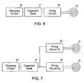
- Fig. 6 Basic elements of magnetic stimulation unit are shown on Fig. 6 .
- the invention uses the principle of capacitor bank (17) charging over the charging circuit (16) which allows capacitors to be charged to different voltage levels. When voltage level on capacitors achieves defined voltage, charging is stopped. Processing unit is then allowed to send signal to the firing circuit (18) of the magnetic stimulation unit (7, Fig. 1 ), which discharges the capacitors over the inductor (10) generating the high intensity current pulse through the inductor. High intensity current pulse generates high intensity magnetic field that is capable to stimulate muscle contraction.
- this invention deals with different ways of connection between inductors and magnetic stimulation units. Basically it recognizes two different types of magnetic stimulation units.
- First type of magnetic stimulation unit ( Fig. 6 ) contains one firing circuit (18) used to discharge capacitors (17) through the inductor (10). In this type of magnetic stimulation unit one capacitor bank is discharged over only one inductor.
- Second type of magnetic stimulation unit ( Fig. 7 ) contains two or more firing circuits (18, 22) used to discharge one capacitor bank (17) through two or more inductors (10, 15) while each inductor corresponds to one firing circuit.
- the number and type of magnetic stimulation units, as well as the number of inductors in the water vessel (bathtub, shower booth or similar) could vary depending on the bathtub model. Two described types of magnetic stimulation units differ with regard to production cost and number of magnetic pulses they are capable to generate in a single inductor. Both types of magnetic field units ( Fig. 6, Fig. 7 ) contain one capacitor bank (17) which is charged over the charging circuit (16). Having in mind that capacitor charging is time consuming process, the first type of the magnetic stimulation unit ( Fig. 6 ) spends time necessary for capacitor charging for the purposes of one inductor only, while the other type of magnetic stimulation unit ( Fig. 7 ) spends the same amount of time for the purposes of two different inductors (10, 15).
- second type of magnetic stimulation unit equipped with more than one firing circuit ( Fig. 7 ), is capable to generate the same number of charging cycles per unit time as the magnetic stimulation unit with one firing circuit ( Fig. 6 ), but in the latter case, the same number of charging cycles is used for magnetic pulses on two inductors (10, 15, Fig. 7 ).
- magnetic stimulation unit with more than one firing circuit and only one capacitor bank has lower production cost since several inductors use the same capacitor bank and one charging circuit. Because of this, the apparatus presented here can be equipped with one or more inductors and can combine different types of magnetic stimulation units to which inductors are connected.
- Fig. 8 shows the processing unit (1) connected to one magnetic stimulation unit with two firing circuits (18, 22) which, through inductors (10, 15) fire the charge from one capacitor bank (17).
- processing unit is connected with two additional magnetic stimulation units each with one firing circuit (25, 29) over which the charge from capacitor banks (24, 28) is fired through inductors (26, 30). These two capacitor banks are charged over separate charging circuits (23, 27).
- Inductors (10, 15, Fig. 4 ) for neuromuscular stimulation are well explained in prior art. Several different types of inductors are described and common usage includes circular and butterfly shaped inductors. Inductors usually use large diameter wire with small number of wounds and are characterized by low level of electrical resistance.
- Water vessel (8, Fig. 4 ) is usually used in the form of bathtub or shower booth. Bathtub can be additionally equipped with hydro and air massage systems. Vessel should be designed ergonomically in such way that muscular trigger points of the user ideally fit the position of inductors.
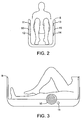
- Fig. 3 shows bathtub equipped with magnetic inductor (10) the position of which fits the trigger point of one of the user's muscles. This location allows inductor to generate magnetic field at position at which it is possible to produce muscular contraction with lowest possible intensity of the magnetic field.
- Position sensors or switches (11, 12, 13, 14, Fig. 4 ) are placed in the vicinity of magnetic inductors in order to detect the presence of user's body. Information about the presence of the user's body is sent to the processing unit. In case the apparatus is activated, processing unit checks the status of position sensors or switches, and in case sensors detect that user's body is in proper position, processing unit initiates magnetic field stimulation. Series of magnetic pulses produce contraction of muscles located close to the inductors.
- Prior art includes large number of position sensors that use ultrasound, light, laser, capacitive, inductive or other methods to detect position of the user's body.
- Body pressure over the switch would either open or close the switch circuit and send signal to the processing unit.
- One of the embodiments of the switch circuit is presented on Fig. 5 ., where the switch (11) is directly connected to the processing unit. Switch is also connected to the ground potential presenting the logical 0 and, over the pull up resistor (20), to the voltage (+5V) representing the logical 1. In this case, switch pressed by the user's body sends logical 0, while absence of user's body sends logical 1 to the processing unit.
- User interface system comprises the keyboard (3, Fig. 1 ) and display (4).
- Keyboard and display (usually LCD) are connected directly to the processing unit.
- processing unit checks the state of the keyboard and determines which of the buttons is pressed. In case that button is pressed, the software of the processing unit decides about procedures that should be activated.
- LCD is also connected to the processing unit directly and is updated in certain time intervals.
- Communication system (5) with other devices or systems is internally supported by the processing unit.
- the communication with other devices could be accomplished over the USB, Ethernet, CAN, RS232, RS485, SPI or other types of communication.
- the communication system allows the connection of the presented apparatus to other devices such as PC, Bathtub controller, mobile phone, audio devices and similar.
- USB communication can be accomplished by direct connection of the processing unit (1) with the USB port.
- SPI communication is accomplished in very short distances by direct connection of the processing unit (1) with processing units of other devices.
- RS232, RS485, CAN and Ethernet communication require driver integrated circuits witch are, on one side, directly connected to the processing unit (1), while on the other side driver circuits are connected to the corresponding connector.
- communication system (5) supports wireless connection that is accomplished with any RF integrated circuit connected directly to the processing unit (1) on one side, and to antenna on the other side.
- One of the RF solutions includes usage of Bluetooth integrated circuit which allows radio communication on short distances.
- processing unit can also be connected to any of the available infrared communication circuits.
- Apparatus for underwater muscle stimulation is designed to stimulate neuromuscular tissue and produce muscle contraction using the high intensity magnetic pulse fired in the proximity of the user's muscular trigger point. This pulse is generated within the magnetic stimulation unit ( Fig. 6 ) which, using the firing circuit (18), instantly fires the charge from the capacitor bank (16) through the inductor (10). Powerful current pulse through the inductor wires produces magnetic pulse of high induction which is capable to depolarize neuromuscular cells in the proximity of the inductor.
- the apparatus allows the user to define treatment parameters using the external memory reader/writer (6, Fig. 1 ) by putting either CD, DVD, or any type of flash memory cards (SD, MMC).
- Position sensors/switches (11, 12, 13, 14, Fig. 4 ) recognize the presence of muscles and activate series of pulses according to the chosen therapy parameters only through inductors close to which user's muscles are detected.
Landscapes
- Health & Medical Sciences (AREA)
- Animal Behavior & Ethology (AREA)
- Biomedical Technology (AREA)
- Nuclear Medicine, Radiotherapy & Molecular Imaging (AREA)
- Radiology & Medical Imaging (AREA)
- Life Sciences & Earth Sciences (AREA)
- Engineering & Computer Science (AREA)
- General Health & Medical Sciences (AREA)
- Public Health (AREA)
- Veterinary Medicine (AREA)
- Magnetic Treatment Devices (AREA)
- Electrotherapy Devices (AREA)
- Finger-Pressure Massage (AREA)
Applications Claiming Priority (2)
| Application Number | Priority Date | Filing Date | Title |
|---|---|---|---|
| RSP-2007/0289A RS51004B (sr) | 2007-07-03 | 2007-07-03 | Uređaj za podvodnu mišićnu stimulaciju |
| PCT/RS2008/000015 WO2009005385A2 (en) | 2007-07-03 | 2008-05-30 | Apparatus for underwater muscle stimulation |
Publications (2)
| Publication Number | Publication Date |
|---|---|
| EP2167191A2 EP2167191A2 (en) | 2010-03-31 |
| EP2167191B1 true EP2167191B1 (en) | 2010-12-01 |
Family
ID=40084147
Family Applications (1)
| Application Number | Title | Priority Date | Filing Date |
|---|---|---|---|
| EP08766999A Active EP2167191B1 (en) | 2007-07-03 | 2008-05-30 | Apparatus for underwater muscle stimulation |
Country Status (5)
| Country | Link |
|---|---|
| EP (1) | EP2167191B1 (sr) |
| AT (1) | ATE489992T1 (sr) |
| DE (1) | DE602008003817D1 (sr) |
| RS (1) | RS51004B (sr) |
| WO (1) | WO2009005385A2 (sr) |
Cited By (1)
| Publication number | Priority date | Publication date | Assignee | Title |
|---|---|---|---|---|
| WO2014075183A1 (en) * | 2012-11-13 | 2014-05-22 | Talebinejad Mehran | Circuit and method for use in transcranial magnetic stimulation |
Family Cites Families (7)
| Publication number | Priority date | Publication date | Assignee | Title |
|---|---|---|---|---|
| US5047005A (en) * | 1987-01-28 | 1991-09-10 | Cadwell Industries, Inc. | Method and apparatus for magnetically stimulating neurons |
| WO1996011723A1 (en) * | 1994-10-17 | 1996-04-25 | Australasian Medical Technology Limited | Devices and methods for implementation of pulsed electromagnetic field therapy |
| IL114162A (en) * | 1995-06-15 | 1999-03-12 | Ostrow Alvin Stewart | Submersive therapy apparatus |
| IT240996Y1 (it) * | 1996-11-07 | 2001-04-20 | Kalor Thermotechnik G M B H | Vasca da bagno ad azione magnetoterapica |
| DE19824504C2 (de) * | 1998-06-02 | 2001-08-16 | Albrecht Struppler | Vorrichtung zur Stimulation eines Körperteils |
| AU4616699A (en) * | 1999-07-01 | 2001-01-22 | Alberto Luis Campos Suner | Hydromagnetotherapy system |
| DE10242542A1 (de) * | 2002-09-13 | 2004-04-01 | Forschungszentrum Karlsruhe Gmbh | Positioniersystem für die navigierte transkranielle Magnetstimulation |
-
2007
- 2007-07-03 RS RSP-2007/0289A patent/RS51004B/sr unknown
-
2008
- 2008-05-30 EP EP08766999A patent/EP2167191B1/en active Active
- 2008-05-30 AT AT08766999T patent/ATE489992T1/de not_active IP Right Cessation
- 2008-05-30 DE DE602008003817T patent/DE602008003817D1/de active Active
- 2008-05-30 WO PCT/RS2008/000015 patent/WO2009005385A2/en not_active Ceased
Cited By (2)
| Publication number | Priority date | Publication date | Assignee | Title |
|---|---|---|---|---|
| WO2014075183A1 (en) * | 2012-11-13 | 2014-05-22 | Talebinejad Mehran | Circuit and method for use in transcranial magnetic stimulation |
| US9504846B2 (en) | 2012-11-13 | 2016-11-29 | Mehran TALEBINEJAD | Circuit and method for use in transcranial magnetic stimulation |
Also Published As
| Publication number | Publication date |
|---|---|
| WO2009005385A2 (en) | 2009-01-08 |
| EP2167191A2 (en) | 2010-03-31 |
| DE602008003817D1 (de) | 2011-01-13 |
| WO2009005385A3 (en) | 2009-03-05 |
| ATE489992T1 (de) | 2010-12-15 |
| RS20070289A (sr) | 2009-05-06 |
| RS51004B (sr) | 2010-10-31 |
Similar Documents
| Publication | Publication Date | Title |
|---|---|---|
| US10413735B2 (en) | Systems and methods for transcutaneous control of implantable pulse generators for neuromodulation | |
| US20170209693A1 (en) | Transcutaneous electrical nerve stimulation (tens) apparatus | |
| CN106345057B (zh) | 一种电针刺激智能塑身内衣系统 | |
| CN105536142B (zh) | 一种智能电针仪 | |
| JP2006043467A (ja) | 埋込み可能な医療装置 | |
| IL183500A0 (en) | Method and apparatus for waking a person | |
| CN109731221A (zh) | 一种多功能神经肌肉电刺激装置 | |
| CN103212157A (zh) | 双极性通用神经电刺激仪 | |
| EP2167191A2 (en) | Apparatus for underwater muscle stimulation | |
| CN205108742U (zh) | 神经肌肉电刺激治疗仪 | |
| RU90991U1 (ru) | УСТРОЙСТВО ЭЛЕКТРОМАГНИТНОЙ БЕСКОНТАКТНОЙ ТЕРАПИИ, ВСТРОЕННОЕ В МОБИЛЬНЫЙ ТЕЛЕФОН, ИЛИ КПК, ИЛИ КОММУНИКАТОР, ИЛИ i-PHONE | |
| EP3492138A1 (en) | Electrical stimulator apparatus with contactless feedback from a user | |
| KR101302074B1 (ko) | 휴대 단말기용 전자침 | |
| CN112704628B (zh) | 手指按摩设备的控制方法、相关装置及计算机存储介质 | |
| CN108744274B (zh) | 一种磁感应控制的体内植入医疗装置控制系统 | |
| CN213049011U (zh) | 一种电疗分指板 | |
| CN202605281U (zh) | 一种脚底穴位调理装置 | |
| CN102631748A (zh) | 移动终端及电疗方法 | |
| CN111491227B (zh) | 耳机控制方法、装置、电子设备和存储介质 | |
| CN104056356A (zh) | 一种音频电疗仪 | |
| EP0620025A1 (en) | Microprocessor-based nerve and muscle stimulator for localized application | |
| CN202554749U (zh) | 具有电疗功能的移动终端 | |
| WO2019055943A1 (en) | PROCESSING DEVICE COMPRISING A WIRELESS INTERFACE AND A USER APPLICATION | |
| CN115212457A (zh) | 基于医疗设备的控制方法、刺激器、电子设备和存储介质 | |
| CN215426952U (zh) | 一种电刺激输出装置及电刺激治疗系统 |
Legal Events
| Date | Code | Title | Description |
|---|---|---|---|
| PUAI | Public reference made under article 153(3) epc to a published international application that has entered the european phase |
Free format text: ORIGINAL CODE: 0009012 |
|
| 17P | Request for examination filed |
Effective date: 20091228 |
|
| AK | Designated contracting states |
Kind code of ref document: A2 Designated state(s): AT BE BG CH CY CZ DE DK EE ES FI FR GB GR HR HU IE IS IT LI LT LU LV MC MT NL NO PL PT RO SE SI SK TR |
|
| AX | Request for extension of the european patent |
Extension state: AL BA MK RS |
|
| RAP1 | Party data changed (applicant data changed or rights of an application transferred) |
Owner name: KOLPA, D.D. METLIKA |
|
| RIN1 | Information on inventor provided before grant (corrected) |
Inventor name: RANDJELOVIC, VLADIMIR |
|
| GRAP | Despatch of communication of intention to grant a patent |
Free format text: ORIGINAL CODE: EPIDOSNIGR1 |
|
| RAX | Requested extension states of the european patent have changed |
Extension state: BA Payment date: 20091228 Extension state: RS Payment date: 20091228 |
|
| GRAS | Grant fee paid |
Free format text: ORIGINAL CODE: EPIDOSNIGR3 |
|
| GRAA | (expected) grant |
Free format text: ORIGINAL CODE: 0009210 |
|
| AK | Designated contracting states |
Kind code of ref document: B1 Designated state(s): AT BE BG CH CY CZ DE DK EE ES FI FR GB GR HR HU IE IS IT LI LT LU LV MC MT NL NO PL PT RO SE SI SK TR |
|
| AX | Request for extension of the european patent |
Extension state: BA RS |
|
| REG | Reference to a national code |
Ref country code: GB Ref legal event code: FG4D |
|
| REG | Reference to a national code |
Ref country code: CH Ref legal event code: EP |
|
| REG | Reference to a national code |
Ref country code: IE Ref legal event code: FG4D |
|
| REF | Corresponds to: |
Ref document number: 602008003817 Country of ref document: DE Date of ref document: 20110113 Kind code of ref document: P |
|
| REG | Reference to a national code |
Ref country code: NL Ref legal event code: VDEP Effective date: 20101201 |
|
| PG25 | Lapsed in a contracting state [announced via postgrant information from national office to epo] |
Ref country code: LT Free format text: LAPSE BECAUSE OF FAILURE TO SUBMIT A TRANSLATION OF THE DESCRIPTION OR TO PAY THE FEE WITHIN THE PRESCRIBED TIME-LIMIT Effective date: 20101201 Ref country code: NO Free format text: LAPSE BECAUSE OF FAILURE TO SUBMIT A TRANSLATION OF THE DESCRIPTION OR TO PAY THE FEE WITHIN THE PRESCRIBED TIME-LIMIT Effective date: 20110301 |
|
| LTIE | Lt: invalidation of european patent or patent extension |
Effective date: 20101201 |
|
| PG25 | Lapsed in a contracting state [announced via postgrant information from national office to epo] |
Ref country code: AT Free format text: LAPSE BECAUSE OF FAILURE TO SUBMIT A TRANSLATION OF THE DESCRIPTION OR TO PAY THE FEE WITHIN THE PRESCRIBED TIME-LIMIT Effective date: 20101201 Ref country code: SI Free format text: LAPSE BECAUSE OF FAILURE TO SUBMIT A TRANSLATION OF THE DESCRIPTION OR TO PAY THE FEE WITHIN THE PRESCRIBED TIME-LIMIT Effective date: 20101201 Ref country code: SE Free format text: LAPSE BECAUSE OF FAILURE TO SUBMIT A TRANSLATION OF THE DESCRIPTION OR TO PAY THE FEE WITHIN THE PRESCRIBED TIME-LIMIT Effective date: 20101201 Ref country code: HR Free format text: LAPSE BECAUSE OF FAILURE TO SUBMIT A TRANSLATION OF THE DESCRIPTION OR TO PAY THE FEE WITHIN THE PRESCRIBED TIME-LIMIT Effective date: 20101201 Ref country code: BG Free format text: LAPSE BECAUSE OF FAILURE TO SUBMIT A TRANSLATION OF THE DESCRIPTION OR TO PAY THE FEE WITHIN THE PRESCRIBED TIME-LIMIT Effective date: 20110301 Ref country code: FI Free format text: LAPSE BECAUSE OF FAILURE TO SUBMIT A TRANSLATION OF THE DESCRIPTION OR TO PAY THE FEE WITHIN THE PRESCRIBED TIME-LIMIT Effective date: 20101201 Ref country code: LV Free format text: LAPSE BECAUSE OF FAILURE TO SUBMIT A TRANSLATION OF THE DESCRIPTION OR TO PAY THE FEE WITHIN THE PRESCRIBED TIME-LIMIT Effective date: 20101201 Ref country code: CY Free format text: LAPSE BECAUSE OF FAILURE TO SUBMIT A TRANSLATION OF THE DESCRIPTION OR TO PAY THE FEE WITHIN THE PRESCRIBED TIME-LIMIT Effective date: 20101201 Ref country code: NL Free format text: LAPSE BECAUSE OF FAILURE TO SUBMIT A TRANSLATION OF THE DESCRIPTION OR TO PAY THE FEE WITHIN THE PRESCRIBED TIME-LIMIT Effective date: 20101201 |
|
| PG25 | Lapsed in a contracting state [announced via postgrant information from national office to epo] |
Ref country code: GR Free format text: LAPSE BECAUSE OF FAILURE TO SUBMIT A TRANSLATION OF THE DESCRIPTION OR TO PAY THE FEE WITHIN THE PRESCRIBED TIME-LIMIT Effective date: 20110302 |
|
| PG25 | Lapsed in a contracting state [announced via postgrant information from national office to epo] |
Ref country code: ES Free format text: LAPSE BECAUSE OF FAILURE TO SUBMIT A TRANSLATION OF THE DESCRIPTION OR TO PAY THE FEE WITHIN THE PRESCRIBED TIME-LIMIT Effective date: 20110312 Ref country code: BE Free format text: LAPSE BECAUSE OF FAILURE TO SUBMIT A TRANSLATION OF THE DESCRIPTION OR TO PAY THE FEE WITHIN THE PRESCRIBED TIME-LIMIT Effective date: 20101201 Ref country code: EE Free format text: LAPSE BECAUSE OF FAILURE TO SUBMIT A TRANSLATION OF THE DESCRIPTION OR TO PAY THE FEE WITHIN THE PRESCRIBED TIME-LIMIT Effective date: 20101201 Ref country code: CZ Free format text: LAPSE BECAUSE OF FAILURE TO SUBMIT A TRANSLATION OF THE DESCRIPTION OR TO PAY THE FEE WITHIN THE PRESCRIBED TIME-LIMIT Effective date: 20101201 Ref country code: PT Free format text: LAPSE BECAUSE OF FAILURE TO SUBMIT A TRANSLATION OF THE DESCRIPTION OR TO PAY THE FEE WITHIN THE PRESCRIBED TIME-LIMIT Effective date: 20110401 Ref country code: IS Free format text: LAPSE BECAUSE OF FAILURE TO SUBMIT A TRANSLATION OF THE DESCRIPTION OR TO PAY THE FEE WITHIN THE PRESCRIBED TIME-LIMIT Effective date: 20110401 |
|
| PG25 | Lapsed in a contracting state [announced via postgrant information from national office to epo] |
Ref country code: SK Free format text: LAPSE BECAUSE OF FAILURE TO SUBMIT A TRANSLATION OF THE DESCRIPTION OR TO PAY THE FEE WITHIN THE PRESCRIBED TIME-LIMIT Effective date: 20101201 Ref country code: RO Free format text: LAPSE BECAUSE OF FAILURE TO SUBMIT A TRANSLATION OF THE DESCRIPTION OR TO PAY THE FEE WITHIN THE PRESCRIBED TIME-LIMIT Effective date: 20101201 Ref country code: PL Free format text: LAPSE BECAUSE OF FAILURE TO SUBMIT A TRANSLATION OF THE DESCRIPTION OR TO PAY THE FEE WITHIN THE PRESCRIBED TIME-LIMIT Effective date: 20101201 |
|
| PLBE | No opposition filed within time limit |
Free format text: ORIGINAL CODE: 0009261 |
|
| STAA | Information on the status of an ep patent application or granted ep patent |
Free format text: STATUS: NO OPPOSITION FILED WITHIN TIME LIMIT |
|
| PG25 | Lapsed in a contracting state [announced via postgrant information from national office to epo] |
Ref country code: DK Free format text: LAPSE BECAUSE OF FAILURE TO SUBMIT A TRANSLATION OF THE DESCRIPTION OR TO PAY THE FEE WITHIN THE PRESCRIBED TIME-LIMIT Effective date: 20101201 |
|
| 26N | No opposition filed |
Effective date: 20110902 |
|
| REG | Reference to a national code |
Ref country code: DE Ref legal event code: R097 Ref document number: 602008003817 Country of ref document: DE Effective date: 20110902 |
|
| PG25 | Lapsed in a contracting state [announced via postgrant information from national office to epo] |
Ref country code: MT Free format text: LAPSE BECAUSE OF FAILURE TO SUBMIT A TRANSLATION OF THE DESCRIPTION OR TO PAY THE FEE WITHIN THE PRESCRIBED TIME-LIMIT Effective date: 20101201 Ref country code: IT Free format text: LAPSE BECAUSE OF FAILURE TO SUBMIT A TRANSLATION OF THE DESCRIPTION OR TO PAY THE FEE WITHIN THE PRESCRIBED TIME-LIMIT Effective date: 20101201 Ref country code: MC Free format text: LAPSE BECAUSE OF NON-PAYMENT OF DUE FEES Effective date: 20110531 |
|
| REG | Reference to a national code |
Ref country code: FR Ref legal event code: ST Effective date: 20120131 |
|
| REG | Reference to a national code |
Ref country code: IE Ref legal event code: MM4A |
|
| REG | Reference to a national code |
Ref country code: DE Ref legal event code: R119 Ref document number: 602008003817 Country of ref document: DE Effective date: 20111201 |
|
| PG25 | Lapsed in a contracting state [announced via postgrant information from national office to epo] |
Ref country code: IE Free format text: LAPSE BECAUSE OF NON-PAYMENT OF DUE FEES Effective date: 20110530 Ref country code: FR Free format text: LAPSE BECAUSE OF NON-PAYMENT OF DUE FEES Effective date: 20110531 |
|
| REG | Reference to a national code |
Ref country code: CH Ref legal event code: PL |
|
| GBPC | Gb: european patent ceased through non-payment of renewal fee |
Effective date: 20120530 |
|
| PG25 | Lapsed in a contracting state [announced via postgrant information from national office to epo] |
Ref country code: CH Free format text: LAPSE BECAUSE OF NON-PAYMENT OF DUE FEES Effective date: 20120531 Ref country code: LI Free format text: LAPSE BECAUSE OF NON-PAYMENT OF DUE FEES Effective date: 20120531 |
|
| PG25 | Lapsed in a contracting state [announced via postgrant information from national office to epo] |
Ref country code: GB Free format text: LAPSE BECAUSE OF NON-PAYMENT OF DUE FEES Effective date: 20120530 |
|
| PG25 | Lapsed in a contracting state [announced via postgrant information from national office to epo] |
Ref country code: LU Free format text: LAPSE BECAUSE OF NON-PAYMENT OF DUE FEES Effective date: 20110530 |
|
| PG25 | Lapsed in a contracting state [announced via postgrant information from national office to epo] |
Ref country code: DE Free format text: LAPSE BECAUSE OF NON-PAYMENT OF DUE FEES Effective date: 20111201 |
|
| PG25 | Lapsed in a contracting state [announced via postgrant information from national office to epo] |
Ref country code: TR Free format text: LAPSE BECAUSE OF FAILURE TO SUBMIT A TRANSLATION OF THE DESCRIPTION OR TO PAY THE FEE WITHIN THE PRESCRIBED TIME-LIMIT Effective date: 20101201 |
|
| PG25 | Lapsed in a contracting state [announced via postgrant information from national office to epo] |
Ref country code: HU Free format text: LAPSE BECAUSE OF FAILURE TO SUBMIT A TRANSLATION OF THE DESCRIPTION OR TO PAY THE FEE WITHIN THE PRESCRIBED TIME-LIMIT Effective date: 20101201 |