EP2167255B1 - Verfahren und werkzeug zum aufweiten eines rohrendes - Google Patents
Verfahren und werkzeug zum aufweiten eines rohrendes Download PDFInfo
- Publication number
- EP2167255B1 EP2167255B1 EP08761637.1A EP08761637A EP2167255B1 EP 2167255 B1 EP2167255 B1 EP 2167255B1 EP 08761637 A EP08761637 A EP 08761637A EP 2167255 B1 EP2167255 B1 EP 2167255B1
- Authority
- EP
- European Patent Office
- Prior art keywords
- piston
- cone
- jaws
- tool
- pipe end
- Prior art date
- Legal status (The legal status is an assumption and is not a legal conclusion. Google has not performed a legal analysis and makes no representation as to the accuracy of the status listed.)
- Active
Links
Images


Classifications
-
- B—PERFORMING OPERATIONS; TRANSPORTING
- B21—MECHANICAL METAL-WORKING WITHOUT ESSENTIALLY REMOVING MATERIAL; PUNCHING METAL
- B21D—WORKING OR PROCESSING OF SHEET METAL OR METAL TUBES, RODS OR PROFILES WITHOUT ESSENTIALLY REMOVING MATERIAL; PUNCHING METAL
- B21D41/00—Application of procedures in order to alter the diameter of tube ends
- B21D41/02—Enlarging
- B21D41/026—Enlarging by means of mandrels
-
- B—PERFORMING OPERATIONS; TRANSPORTING
- B29—WORKING OF PLASTICS; WORKING OF SUBSTANCES IN A PLASTIC STATE IN GENERAL
- B29C—SHAPING OR JOINING OF PLASTICS; SHAPING OF MATERIAL IN A PLASTIC STATE, NOT OTHERWISE PROVIDED FOR; AFTER-TREATMENT OF THE SHAPED PRODUCTS, e.g. REPAIRING
- B29C57/00—Shaping of tube ends, e.g. flanging, belling or closing; Apparatus therefor, e.g. collapsible mandrels
- B29C57/02—Belling or enlarging, e.g. combined with forming a groove
- B29C57/04—Belling or enlarging, e.g. combined with forming a groove using mechanical means
- B29C57/045—Belling or enlarging, e.g. combined with forming a groove using mechanical means rotating
Definitions
- the invention relates to a method for expanding a pipe end with the aid of an expander tool, the expander tool comprising a plurality of jaws that are radially movable in relation to a center axis between a retracted and an outer expanded position, wherein said jaws have outer jaw surfaces which are intended for engagement with the inner surface of the pipe end and which lie adjacent to one another in the retracted position of the jaws and have an at least generally circular arcuate shape in cross-section, and a piston or cone with a tapered end for moving the jaws between said positions, whereby the piston is moved in a reciprocating manner in the axial direction for expanding the pipe end gradually in stages.
- the invention relates to a tool for expanding a pipe end, the tool comprising a plurality of jaws which are radially movable in relation to a center axis between a retracted position and an outer expanding position and which, when retracted, are intended to be inserted into the pipe end, wherein the movable jaws have outer jaw surfaces which are intended for engagement with the inner surface of the pipe end and which lie adjacent to one another in the retracted position of the jaws and have an at least generally circular arcuate cross section, a piston with a tapered end for moving the jaws between said positions, and means moving the piston in a reciprocating manner in the axial direction for expanding the pipe end gradually in stages.
- a clamping sleeve made of a resilient material, for instance metal or plastic, which may be the same plastic material as the material from which the pipe is made, is expanded and shrunk over the pipe end in order to further enhance the holding and the sealing pressure in the pipe connecting region.
- the clamping sleeve can be expanded at the same time as the pipe end is expanded, with the clamping sleeve in position around said pipe end.
- EP 0417674 discloses an expander tool for expanding a pipe end.
- the expander tool includes a number of jaws, which can be moved radially in relation to a center axis between a retracted position, in which the jaws lie close together, and an outer, pipe expanding position.
- the jaws have outer jaw surfaces, which are delimited by mutually opposing jaw edges and are intended for engagement with the inner surface of the pipe end and which are at least essentially circularly arcuate in shape when seen in cross-section.
- the opposing edges of the outer jaw surfaces tend to produce on the inner surface of the pipe end continuous grooves or score lines, which extend in the direction of the longitudinal axis of the pipe.
- EP 0682758 discloses a corresponding expander tool also comprising recesses on the outer surface of the jaws. These recesses cause promontories on the inner surface of the pipe by causing interruptions in the score lines that are liable to be formed by the jaw edges on the inner surface of the pipe end during the final stage of the pipe end expansion process. However, the result is that the inner surface of the pipe end is not even, whereby the pipe connection is not always tight enough.
- the method is repeated until the pipe end has been expanded to the extent desired, for instance until the outer jaw surfaces have been inserted at full length into the pipe end and brought to an expanded state, whereupon the jaws are withdrawn from said pipe end after having been returned to the retracted state or position.
- using the tool requires carefulness and quite high skills in order to ensure that the connection is tight enough.
- EP 1118401 discloses an expander tool in which the jaws are mounted in a bushing.
- the jaws are brought to an expanded state by a tapered piston.
- the bushing and thereby the jaws are axially movable.
- the expanded state of the jaws is larger.
- the axial displacement of the jaws allows widening of the pipe end in stages.
- the structure of the expander tool is rather complicated and it is quite difficult to manufacture the tool and use the tool to achieve a tight enough connection.
- DE 199 24 695 discloses an expander tool for hollow bodies such as plastic pipes.
- the object of the invention is to provide a new method and tool for expanding pipe ends.
- the method of the invention is characterized in that the axial reciprocating movement of the piston is guided to rotate the jaws to a certain extent in the circumferential direction after each expansion stage.
- the tool of the invention is characterized by means for guiding the axial reciprocating movement of the piston to rotate the jaws to a certain extent in the circumferential direction after each expansion stage.
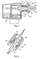
- Figure 1 is a schematic cross-sectional side view of an expander tool
- Figure 3 is a similar view as in Figure 2 , but without a piston
- Figures 4a - 4g are schematic views illustrating the function of a rotating system
- Figure 5 is a schematic cross-sectional side view of a part of a second expander tool
- Figure 6 is a schematic cross-sectional side view of a part of a third expander tool
- Figure 9 is a schematic view of a rotation bushing shown in Figure 6 .
- Figure 10 is a schematic cross-sectional side view of a part of a fourth expander tool
- Figure 11 is a schematic view of an auxiliary piston shown in Figure 10 .
- Figure 13 is a schematic cross-sectional side view along line A - A of Figure 12 .
- the sleeve 12 is provided with fingers 15, which rotate the jaws 10 when the sleeve 12 is rotating.
- the rear ends of the jaws 10 are provided with cuts, into which the fingers 15 are attached.
- the number of fingers 15 may be such that each jaw 10 is provided with its own finger 15. However, if the sleeve 12 is only rotating when the jaws 10 are substantially in the retracted position, a smaller number of fingers 15, such as two or even one, may be enough.
- Figure 5 shows an embodiment, in which an auxiliary twister 17 is attached with threads to the end of a housing 5 of a conventional expander tool, which originally does not have a mechanism for rotating the jaws 10.
- the auxiliary twister 17 comprises a stationary housing 18.
- An expander tool corresponding to the expander tool 6 shown in Figure 1 is attached to the end of the housing 18. For the sake of clarity, however, the expander tool is not shown in Figure 5 .
- the amount of rotation and thus the distance between the straight parts 16b of the groove 13 may be selected as needed.
- the rotation is larger than the distance between the edges of the jaws 10 when the jaws are in their expanded position.
- the angle of rotation may vary, for example, between 20° and 50°.
- the cover 7 and the jaws 10 are arranged such that they do not rotate with respect to each other.
- the rotating sleeve 12 is arranged to rotate the cover 7, which then rotates the jaws 10.
- the expansion in stages is implemented by forming the outer jaw surfaces such that they enlarge from their insertion ends to the rear ends.
- the expansion in stages can also be implemented with jaws whose radial distance does not increase but, for example, the tapered end of the piston is pushed deeper and deeper inside the jaws in successive expansion stages.
- the structure described in EP 1 118401 could be used.
- the jaws are rotated after each expansion a certain amount in the circumferential direction by guiding the reciprocating motion of the piston to rotate the jaws a certain amount in the circumferential direction.
Landscapes
- Engineering & Computer Science (AREA)
- Mechanical Engineering (AREA)
- Hand Tools For Fitting Together And Separating, Or Other Hand Tools (AREA)
- Turning (AREA)
- Shaping Of Tube Ends By Bending Or Straightening (AREA)
- Earth Drilling (AREA)
Claims (16)
- Ein Verfahren zum Aufweiten eines Rohrendes mithilfe eines Aufweitungswerkzeugs (1), das Aufweitungswerkzeug (1) aufweisend
eine Vielzahl von Klauen (10), die radial beweglich sind in Bezug auf eine Zentrumsachse zwischen einer zurückgezogenen und einer äußeren geweiteten Position, wobei die Klauen (10) äußere Klauenoberflächen aufweisen, die vorgesehen sind für ein Eingreifen mit der inneren Oberfläche des Rohrendes und die in der zurückgezogene Position der Klauen (10) angrenzend zueinander liegen und im Querschnitt eine zumindest im Allegemeinen kreisbogenförmige Form haben, und
einen Kolben (2) oder Konus mit eine zulaufenden Ende zum Bewegen der Klauen (10) zwischen den genannten Positionen;
wobei der Kolben (2) oder Konus zum graduellen stufenweisen Aufweiten des Rohrendes in der axialen Richtung hin- und her bewegt wird, und
die axiale Hin- und Herbewegung des Kolbens (2) oder Konus gelenkt wird, die Klauen (10) nach jeder Aufweitungsstufe zu einem gewissen Grad in der Umfangsrichtung zu drehen. - Ein Verfahren gemäß Anspruch 1, wobei
das Werkzeug (1) eine Hülse (12) um den Kolben (2) oder um den Konus aufweist, wobei die Hülse (12) und der Kolben (2) oder Konus einander zugewandte Oberflächen haben und mit Gräben (13) und Stiften (14) ausgestattet sind,
wobei die axiale Bewegung des Kolbens (2) oder Konus durch die Gräben (13) und Stifte (14) in eine Drehung in die Umfangsrichtung umgesetzt wird. - Ein Verfahren gemäß Anspruch 2,
wobei die Gräben (13) im Kolben (2) oder Konus angeordnet sind und der Stift (14) den Gräben (13) im Kolben (2) oder Konus zur Schaffung der Rotation folgt, um die Klauen (10) zu drehen. - Ein Verfahren gemäß Anspruch 2 oder 3,
wobei der Boden des Grabens (13) niedrige Stellen und hohe Stellen aufweist und der Stift (14) dem Boden des Grabens (13) folgt. - Ein Verfähren gemäß Anspruch 2,
wobei die axiale Belegung des Kolbens (2) oder Konus die Hülse (12) dreht. - Ein Verfahren gemäß Anspruch 1,
wobei das Werkzeug (1) aufweist
eine Buchse (20) um den Kolben (2) oder Konus, wobei die Buchse (20) eine schräge Rührung (21) aufweist, und der Kolben (2) oder Konus mit einem Führungsstift (23) ausgestattet ist, und
ein Kupplungslager (24), wobei das Kupplungslager (24) der Buchse (20) erlaubt, sich in eine Wichtung zu drehen und ein Drehen der Buchse (20) in eine andere Richtung verhindert. - Ein Verfahren gemäß einem der Ansprüche 1, 2, 3, 4 oder 6,
wobei der Kolben (2) oder Konus in einer Weise drehbar ist, dass der rotierend Kolben (2) oder Konus die Klauen dreht. - Ein Werkzeug zum Aufweiten eines Rohrendes, das Werkzeug (1) aufweisend
eine Vielzahl von Klauen (10), die radial beweglich sind in Bezug auf eine Zentrumsachse zwischen einer zurückgezogenen Position und einer äußeren geweiteten Position und die, wenn zurückgezogen, vorgesehen sind, in ein Rohrende eingebracht zu werden, wobei die beweglichen Klauen (10) äußere Klauenoberflächen aufweisen, die für ein Eingreifen mit der inneren Oberfläche des Rohrendes vorgesehen sind und die in der zurückgezogenen Position der Klauen (10) angrenzend zueinander liegen und einen zumindest im Allgemeinen kreisbogenformigen Querschnitt haben,
einen Kolben (2) oder Konus mit einem zulaufenden Ende, um die Klauen zwischen den genannten Positionen zu bewegen,
Mittel, die den Kolben (2) oder Konus in axialer Richtung zum graduellen stufenweisen Aufweiten des Rohrendes hin- und her bewegen; und
Mittel zum Führen der axialen Hin-und Herbewegung des Kolbens (2) oder Konus, um die Klauen (10) in gewissem Masse nach jeder Aufweitungsstufe in der Umfangsrichtung zu drehen. - Ein Werkzeug gemäß Anspruch 8,
wobei das Werkzeug (1) mit einer Hülse (12) um den Kolben (2) oder Konus ausgestattet ist, wobei die Hülse (12) und der Kolben (2) oder Konus mit einander gewandten Oberflächen ausgestattet sind sowie mit Gräben (13) und Stiften (14) für das Ausführen eines gewissen Maßes an Rotation in der Umfangsrichtung ausgestattet sind. - Ein Werkzeug gemäß Anspruch 9,
wobei die Gräben (13) schräge Wände zum Führen der Stifte (14) aufweisen. - Ein Werkzeug gemäß einem der Ansprüche 8 bis 10,
wobei der Kolben (2) order Konus mit Gräben (13) ausgestattet ist und das Werkzeug einen Stift (14) aufweist, der den Gräben (13) folgt, um die rehung der Klauen zu bewirken. - Ein Werkzeug gemäß Anspruch 11,
wobei der Boden des Grabens (13) mit hohen Stellen und tiefen Stellen ausgestattet ist und der Stift (14) angeordnet ist, dem Boden des Grabens (13) zu folgen. - Ein Werkzeug gemäß Anspruch 8,
wobei das Werkzeug (1) mit einer Buchse (20) um den Kolben (2) oder Konus ausgestattet ist, wobei die Buchse (20) mit einer schrägen Führung (21) ausgestattet ist und der Kolben (2) oder Konus mit einem Führungsstift (23) und einem Kupplungslager (24) ausgestattet ist, das der Buchse (20) erlaubt, sich in eine Richtung zu drehen und ein Drehen der Buchse (20) in eine andere Richtung verhindert. - Ein Werkzeug gemäß einem der Ansprüche 8 bis 13,
wobei dem Kolben (2) oder Konus ermöglicht wird, sich um ein bestimmtes Maß in der Umfangsrichtung zu drehen. - Ein Werkzeug gemäß einem der Ansprüche 8 bis 14,
wobei die Mittel zum Ausbilden einer bestimmten Drehbewegung in der Umfangsrichtung innerhalb des Gehäuses (5) des Aufweitungswerkzeugs positioniert sind. - Ein Werkzeug gemäß eine der Ansprüche 8 bis 14,
wobei die Mittel zum Ausbilden der Drehbewegung in der Umfangsrichtung in einem Teil zwischen dem Gehäuse (5) des Werkzeugs (1) und einem Expanderkopf (6) positioniert sind.
Priority Applications (1)
| Application Number | Priority Date | Filing Date | Title |
|---|---|---|---|
| PL08761637.1T PL2167255T5 (pl) | 2007-06-25 | 2008-04-30 | Sposób i narzędzie do rozszerzania końca rury |
Applications Claiming Priority (2)
| Application Number | Priority Date | Filing Date | Title |
|---|---|---|---|
| US94597207P | 2007-06-25 | 2007-06-25 | |
| PCT/FI2008/050241 WO2009000966A1 (en) | 2007-06-25 | 2008-04-30 | Method and tool for expanding a pipe end |
Publications (4)
| Publication Number | Publication Date |
|---|---|
| EP2167255A1 EP2167255A1 (de) | 2010-03-31 |
| EP2167255A4 EP2167255A4 (de) | 2010-09-22 |
| EP2167255B1 true EP2167255B1 (de) | 2013-07-03 |
| EP2167255B2 EP2167255B2 (de) | 2023-08-30 |
Family
ID=40185225
Family Applications (1)
| Application Number | Title | Priority Date | Filing Date |
|---|---|---|---|
| EP08761637.1A Active EP2167255B2 (de) | 2007-06-25 | 2008-04-30 | Verfahren und werkzeug zum aufweiten eines rohrendes |
Country Status (8)
| Country | Link |
|---|---|
| US (1) | US8562331B2 (de) |
| EP (1) | EP2167255B2 (de) |
| CA (1) | CA2690964C (de) |
| ES (1) | ES2433372T5 (de) |
| FI (1) | FI2167255T4 (de) |
| PL (1) | PL2167255T5 (de) |
| PT (1) | PT2167255E (de) |
| WO (1) | WO2009000966A1 (de) |
Cited By (1)
| Publication number | Priority date | Publication date | Assignee | Title |
|---|---|---|---|---|
| IT201800002291A1 (it) * | 2018-02-01 | 2019-08-01 | Matteo Boin | Procedimento per la lavorazione di tubi saldati |
Families Citing this family (38)
| Publication number | Priority date | Publication date | Assignee | Title |
|---|---|---|---|---|
| FR2910828B1 (fr) | 2006-12-28 | 2009-03-06 | Virax Soc Par Actions Simplifi | Dispositif d'outil a expansion pour pince sur machine a realiser des emboitures aux extremites de tuyaux en matiere plastique ou composite |
| FI2167255T4 (fi) | 2007-06-25 | 2023-12-04 | Uponor Innovation Ab | Menetelmä ja työkalu putkenpään laajentamiseen |
| EP2374554B1 (de) | 2010-04-06 | 2017-09-06 | Milwaukee Electric Tool Corporation | PEX-Erweiterungswerkzeug |
| ES2531272T3 (es) | 2010-08-16 | 2015-03-12 | Uponor Innovation Ab | Herramienta y método para expandir un extremo de una tubería |
| ES2637143T3 (es) * | 2011-02-28 | 2017-10-11 | Rothenberger Ag | Dispositivo y procedimiento para abocardar el extremo de un tubo de material sintético |
| DE202011050988U1 (de) * | 2011-08-15 | 2012-11-23 | Rehau Ag + Co. | Vorrichtung zum Aufweiten hohler Werkstücke, insbesondere der Enden von Kunststoffrohren und Metall-Kunststoff-Verbundrohren, sowie dessen Verwendung |
| BR122020016830B1 (pt) * | 2012-02-14 | 2021-01-26 | Diversitech Corporation | dispositivo com expansor de tubo hidráulico |
| DE102012109255A1 (de) * | 2012-09-28 | 2014-04-03 | Gustav Klauke Gmbh | Handarbeitsgerät, Hand-Aufweitgerät, hydraulische Kolben-/Zylinderanordnung und Verfahren zum Betreiben eines Handarbeitsgerätes |
| DE102013107294A1 (de) * | 2013-07-10 | 2015-01-15 | Gustav Klauke Gmbh | Handarbeitsgerät und Hand-Aufweitgerät |
| ITRA20130026A1 (it) * | 2013-12-04 | 2014-03-05 | Ipm Srl | Sistema di formatura per deformazione plastica a caldo dei bicchieri dei tubi in materia plastica con doppia flangia di rincalco a movimenti indipendenti |
| US9914260B2 (en) | 2014-06-20 | 2018-03-13 | Milwaukee Electric Tool Corporation | PEX expanding tool |
| CN104482335A (zh) * | 2014-12-30 | 2015-04-01 | 建新赵氏集团有限公司 | 一种橡胶接头扩口装置 |
| US9862137B2 (en) * | 2015-04-20 | 2018-01-09 | Milwaukee Electric Tool Corporation | PEX expanding tool |
| WO2016201196A1 (en) * | 2015-06-10 | 2016-12-15 | Milwaukee Electric Tool Corporation | Pex expanding tool |
| CN107921697B (zh) * | 2015-06-10 | 2020-10-23 | 米沃奇电动工具公司 | Pex扩张工具 |
| US9975289B2 (en) * | 2016-07-27 | 2018-05-22 | Black & Decker Inc. | PEX expanding tool |
| US11543065B2 (en) | 2016-09-02 | 2023-01-03 | Zurn Industries, Llc | Extruded cold-expansion compression collar |
| US11541581B2 (en) | 2016-09-02 | 2023-01-03 | Zurn Industries, Llc | Injection molded cold-expansion compression collar |
| CA2977581A1 (en) | 2016-09-02 | 2018-03-02 | Zurn Industries, Llc | Injection molded cold-expansion compression collar |
| US11054076B2 (en) | 2016-11-04 | 2021-07-06 | Zurn Industries, Llc | Reinforcing ring with sleeve |
| CN106475480A (zh) * | 2016-12-16 | 2017-03-08 | 东台市远洋不锈钢制造有限公司 | 一种管件扩口整圆机 |
| KR102610635B1 (ko) | 2017-01-05 | 2023-12-08 | 라이프 테크놀로지스 코포레이션 | 튜브 피팅에 튜브를 결합하기 위한 압축 칼라 및 사용 방법 |
| US11415257B2 (en) | 2017-12-22 | 2022-08-16 | S & B Technical Products, Inc. | Apparatus and method for joining molecularly oriented pipe |
| CN108971935A (zh) * | 2018-02-28 | 2018-12-11 | 中信戴卡股份有限公司 | 一种用于将金属管与板材胀接固定的装置 |
| US11633775B2 (en) | 2019-02-20 | 2023-04-25 | Milwaukee Electric Tool Corporation | PEX expansion tool |
| US11596999B2 (en) * | 2019-02-20 | 2023-03-07 | Milwaukee Electric Tool Corporation | PEX expansion tool |
| CN109954800A (zh) * | 2019-03-22 | 2019-07-02 | 佛山市天箭机械设备有限公司 | 一种可快速换模的打凸点装置 |
| CN110154369A (zh) * | 2019-05-24 | 2019-08-23 | 日丰科技有限公司 | 一种扩口钳 |
| US11110646B2 (en) * | 2019-07-23 | 2021-09-07 | Brochman Innovations, Llc | PEX tubing expander head |
| CN214726466U (zh) | 2020-11-27 | 2021-11-16 | 米沃奇电动工具公司 | 扩展工具 |
| CN114850326B (zh) * | 2021-02-03 | 2025-01-28 | 台州巨力工具股份有限公司 | 一种扩管工具的工作组件及电动液压扩管工具 |
| US11779990B2 (en) * | 2021-04-09 | 2023-10-10 | Milwaukee Electric Tool Corporation | Expansion tool |
| JP7734560B2 (ja) * | 2021-11-05 | 2025-09-05 | 株式会社マキタ | 拡管工具 |
| CN114214694B (zh) * | 2021-12-20 | 2024-02-13 | 永臻科技股份有限公司 | 一种气动扩撑工具 |
| JP7760386B2 (ja) * | 2022-01-18 | 2025-10-27 | 株式会社マキタ | 管拡径工具 |
| JP7707089B2 (ja) * | 2022-01-18 | 2025-07-14 | 株式会社マキタ | 管拡径工具 |
| US20250319647A1 (en) * | 2022-06-30 | 2025-10-16 | Makita Corporation | Tube expansion tool |
| US12558834B2 (en) | 2023-01-12 | 2026-02-24 | Black & Decker Inc. | PEX expander |
Family Cites Families (25)
| Publication number | Priority date | Publication date | Assignee | Title |
|---|---|---|---|---|
| US3657666A (en) | 1970-10-29 | 1972-04-18 | Bell Telephone Labor Inc | Spin-flip light scattering and gunn effect-type oscillations in multivalley semiconductors subject to a magnetic field |
| US3857666A (en) | 1973-04-09 | 1974-12-31 | L Barnett | Apparatus for belling ends of conduit or the like |
| DE2511490A1 (de) | 1975-03-15 | 1976-09-23 | Edwin Rothenberger Schweisstec | Vorrichtung zum aufweiten von rohrleitungsenden |
| DE2552607C2 (de) * | 1975-11-24 | 1985-08-01 | Rothenberger GmbH & Co Werkzeuge-Maschinen KG, 6000 Frankfurt | Handwerkzeug zum Aufweiten von Rohrleitungsenden |
| JPS579541A (en) † | 1980-06-18 | 1982-01-19 | Kawasaki Steel Corp | Pipe expander |
| US4378928A (en) * | 1980-06-23 | 1983-04-05 | Beatrice Foods Company | Molding apparatus |
| DE8534175U1 (de) * | 1985-12-05 | 1986-01-30 | John & Co, 7590 Achern | Dorn zum Aufweiten von Rohren |
| US4735078A (en) * | 1986-07-07 | 1988-04-05 | Emerson Electric Co. | Tube expanding tool |
| CA2024394A1 (en) * | 1989-09-14 | 1991-03-15 | Velte Karl-Heinz | Expansion tool for hollow working parts |
| DE4017404C1 (de) * | 1990-05-30 | 1991-10-31 | Rothenberger Werkzeuge-Maschinen Gmbh, 6000 Frankfurt, De | |
| SE500665C2 (sv) | 1993-02-05 | 1994-08-01 | Wirsbo Bruks Ab | Förfarande för upprättande av en rörförbindning samt för användning vid förfarandet lämpat rörförbindningsstycke |
| US5414610A (en) | 1993-06-21 | 1995-05-09 | Ast Research, Inc. | Universal power converter with single, shared power transformation circuit |
| SE501555C2 (sv) | 1993-10-07 | 1995-03-13 | Wirsbo Bruks Ab | Förfarande för expandering av en rörände samt verktyg för genomförande av förfarandet |
| DE29613985U1 (de) * | 1996-08-13 | 1996-11-14 | Wirsbo Rohrproduktion und Vertriebs-GmbH, 63150 Heusenstamm | Spreizwerkzeug mit Rückholvorrichtung |
| US5836197A (en) * | 1996-12-16 | 1998-11-17 | Mckee Machine Tool Corp. | Integral machine tool assemblies |
| DE19924695C2 (de) | 1999-05-28 | 2001-05-10 | Rothenberger Werkzeuge Ag | Expansionswerkzeug für Hohlkörper und Verfahren zu dessen Herstellung |
| EP1118401B1 (de) | 2000-01-21 | 2004-03-31 | Virax S.A. | Aufweitungsvorrichtung zum Formen von Muffen an Rohrenden |
| FR2828125B1 (fr) * | 2001-08-01 | 2003-11-14 | Virax Sa | Dispositif d'outil a expansion pour pince a emboiture |
| DE102005029681A1 (de) * | 2005-06-23 | 2006-12-28 | Universität Dortmund | Vorrichtung und Verfahren zum Fügen nicht-rotationssymmetrischer Hohlprofile durch Weiten mit Formkörpern |
| US7669328B1 (en) * | 2006-04-21 | 2010-03-02 | Robert Bosch Gmbh | Method of manufacturing a push rod |
| FR2910828B1 (fr) * | 2006-12-28 | 2009-03-06 | Virax Soc Par Actions Simplifi | Dispositif d'outil a expansion pour pince sur machine a realiser des emboitures aux extremites de tuyaux en matiere plastique ou composite |
| FI2167255T4 (fi) | 2007-06-25 | 2023-12-04 | Uponor Innovation Ab | Menetelmä ja työkalu putkenpään laajentamiseen |
| JP5194739B2 (ja) * | 2007-11-21 | 2013-05-08 | パナソニック株式会社 | 円筒体の製造方法 |
| DE202008002266U1 (de) * | 2008-02-18 | 2008-04-30 | Novopress Gmbh Pressen Und Presswerkzeuge & Co. Kommanditgesellschaft | Vorrichtung zum Aufweiten von Rohren |
| DE202008002265U1 (de) * | 2008-02-18 | 2008-04-30 | Novopress Gmbh Pressen Und Presswerkzeuge & Co. Kg | Vorrichtung zum Aufweiten von Rohren |
-
2008
- 2008-04-30 FI FIEP08761637.1T patent/FI2167255T4/fi active
- 2008-04-30 PL PL08761637.1T patent/PL2167255T5/pl unknown
- 2008-04-30 PT PT87616371T patent/PT2167255E/pt unknown
- 2008-04-30 WO PCT/FI2008/050241 patent/WO2009000966A1/en not_active Ceased
- 2008-04-30 US US12/666,456 patent/US8562331B2/en active Active
- 2008-04-30 ES ES08761637T patent/ES2433372T5/es active Active
- 2008-04-30 EP EP08761637.1A patent/EP2167255B2/de active Active
- 2008-04-30 CA CA2690964A patent/CA2690964C/en active Active
Cited By (2)
| Publication number | Priority date | Publication date | Assignee | Title |
|---|---|---|---|---|
| IT201800002291A1 (it) * | 2018-02-01 | 2019-08-01 | Matteo Boin | Procedimento per la lavorazione di tubi saldati |
| EP3520923A1 (de) | 2018-02-01 | 2019-08-07 | Matteo Boin | Verfahren zur bearbeitung von geschweissten rohren |
Also Published As
| Publication number | Publication date |
|---|---|
| CA2690964A1 (en) | 2008-12-31 |
| EP2167255A4 (de) | 2010-09-22 |
| ES2433372T3 (es) | 2013-12-10 |
| US8562331B2 (en) | 2013-10-22 |
| EP2167255A1 (de) | 2010-03-31 |
| FI2167255T4 (fi) | 2023-12-04 |
| CA2690964C (en) | 2016-08-02 |
| EP2167255B2 (de) | 2023-08-30 |
| ES2433372T5 (es) | 2024-04-02 |
| PT2167255E (pt) | 2013-10-09 |
| WO2009000966A1 (en) | 2008-12-31 |
| PL2167255T5 (pl) | 2023-12-27 |
| US20100308503A1 (en) | 2010-12-09 |
| PL2167255T3 (pl) | 2013-12-31 |
Similar Documents
| Publication | Publication Date | Title |
|---|---|---|
| EP2167255B1 (de) | Verfahren und werkzeug zum aufweiten eines rohrendes | |
| US9248617B2 (en) | Tool and method for expanding a pipe end | |
| RU2120343C1 (ru) | Способ расширения конца трубы | |
| JP3325894B2 (ja) | 管連結部の形成方法並びにこの方法の実施に適切に使用される工具及び連結スリーブ | |
| US20250276486A1 (en) | Constant strain pex expansion tool head | |
| US8517715B2 (en) | PEX expanding tool | |
| US8801424B2 (en) | Device for expanding hollow bodies | |
| CN104093544B (zh) | 扩张工具的扩张头、包括扩张头的扩张工具 | |
| EP3698941B1 (de) | Werkzeug zur pex-aufweitung | |
| EP3628907B1 (de) | Kaltdehnendes rohranschlussstück, rohrverbindung, system, ausrüstung und verfahren | |
| CN117000766B (zh) | 一种穿孔机的固定夹具 | |
| PL93449B1 (de) | ||
| JPS6045052B2 (ja) | 拡径受口の成形法 | |
| GB2095597A (en) | Expanding solder rings in pipe fittings | |
| KR100192655B1 (ko) | 조인트 및 이것에 사용되는 파이프 끝단부 반전방법과 그 장치 |
Legal Events
| Date | Code | Title | Description |
|---|---|---|---|
| PUAI | Public reference made under article 153(3) epc to a published international application that has entered the european phase |
Free format text: ORIGINAL CODE: 0009012 |
|
| 17P | Request for examination filed |
Effective date: 20091222 |
|
| AK | Designated contracting states |
Kind code of ref document: A1 Designated state(s): AT BE BG CH CY CZ DE DK EE ES FI FR GB GR HR HU IE IS IT LI LT LU LV MC MT NL NO PL PT RO SE SI SK TR |
|
| AX | Request for extension of the european patent |
Extension state: AL BA MK RS |
|
| RIN1 | Information on inventor provided before grant (corrected) |
Inventor name: SCHRAMM, ERVIN, WILLY Inventor name: GOMEZ, AMALIA, BARRAGAN Inventor name: ADELMAN, DUANE, L. Inventor name: EKLUND, JANNE Inventor name: KNAPP, RANDALL, J. |
|
| A4 | Supplementary search report drawn up and despatched |
Effective date: 20100820 |
|
| RIC1 | Information provided on ipc code assigned before grant |
Ipc: B21D 39/20 20060101ALI20100816BHEP Ipc: B29C 57/00 20060101ALI20100816BHEP Ipc: B21D 41/02 20060101AFI20090119BHEP |
|
| DAX | Request for extension of the european patent (deleted) | ||
| 17Q | First examination report despatched |
Effective date: 20110518 |
|
| RAP1 | Party data changed (applicant data changed or rights of an application transferred) |
Owner name: UPONOR INNOVATION AB |
|
| GRAP | Despatch of communication of intention to grant a patent |
Free format text: ORIGINAL CODE: EPIDOSNIGR1 |
|
| RIC1 | Information provided on ipc code assigned before grant |
Ipc: B29C 57/04 20060101ALI20130117BHEP Ipc: B21D 41/02 20060101AFI20130117BHEP |
|
| GRAS | Grant fee paid |
Free format text: ORIGINAL CODE: EPIDOSNIGR3 |
|
| GRAA | (expected) grant |
Free format text: ORIGINAL CODE: 0009210 |
|
| AK | Designated contracting states |
Kind code of ref document: B1 Designated state(s): AT BE BG CH CY CZ DE DK EE ES FI FR GB GR HR HU IE IS IT LI LT LU LV MC MT NL NO PL PT RO SE SI SK TR |
|
| REG | Reference to a national code |
Ref country code: GB Ref legal event code: FG4D |
|
| REG | Reference to a national code |
Ref country code: CH Ref legal event code: EP Ref country code: AT Ref legal event code: REF Ref document number: 619406 Country of ref document: AT Kind code of ref document: T Effective date: 20130715 |
|
| REG | Reference to a national code |
Ref country code: IE Ref legal event code: FG4D |
|
| REG | Reference to a national code |
Ref country code: DE Ref legal event code: R096 Ref document number: 602008025767 Country of ref document: DE Effective date: 20130829 |
|
| REG | Reference to a national code |
Ref country code: PT Ref legal event code: SC4A Free format text: AVAILABILITY OF NATIONAL TRANSLATION Effective date: 20131002 |
|
| REG | Reference to a national code |
Ref country code: SE Ref legal event code: TRGR |
|
| PG25 | Lapsed in a contracting state [announced via postgrant information from national office to epo] |
Ref country code: SI Free format text: LAPSE BECAUSE OF FAILURE TO SUBMIT A TRANSLATION OF THE DESCRIPTION OR TO PAY THE FEE WITHIN THE PRESCRIBED TIME-LIMIT Effective date: 20130703 |
|
| REG | Reference to a national code |
Ref country code: NL Ref legal event code: T3 |
|
| REG | Reference to a national code |
Ref country code: AT Ref legal event code: MK05 Ref document number: 619406 Country of ref document: AT Kind code of ref document: T Effective date: 20130703 |
|
| REG | Reference to a national code |
Ref country code: NO Ref legal event code: T2 Effective date: 20130703 |
|
| REG | Reference to a national code |
Ref country code: ES Ref legal event code: FG2A Ref document number: 2433372 Country of ref document: ES Kind code of ref document: T3 Effective date: 20131210 |
|
| REG | Reference to a national code |
Ref country code: LT Ref legal event code: MG4D |
|
| REG | Reference to a national code |
Ref country code: PL Ref legal event code: T3 |
|
| PG25 | Lapsed in a contracting state [announced via postgrant information from national office to epo] |
Ref country code: HR Free format text: LAPSE BECAUSE OF FAILURE TO SUBMIT A TRANSLATION OF THE DESCRIPTION OR TO PAY THE FEE WITHIN THE PRESCRIBED TIME-LIMIT Effective date: 20130703 Ref country code: CY Free format text: LAPSE BECAUSE OF FAILURE TO SUBMIT A TRANSLATION OF THE DESCRIPTION OR TO PAY THE FEE WITHIN THE PRESCRIBED TIME-LIMIT Effective date: 20130821 Ref country code: LT Free format text: LAPSE BECAUSE OF FAILURE TO SUBMIT A TRANSLATION OF THE DESCRIPTION OR TO PAY THE FEE WITHIN THE PRESCRIBED TIME-LIMIT Effective date: 20130703 Ref country code: AT Free format text: LAPSE BECAUSE OF FAILURE TO SUBMIT A TRANSLATION OF THE DESCRIPTION OR TO PAY THE FEE WITHIN THE PRESCRIBED TIME-LIMIT Effective date: 20130703 Ref country code: IS Free format text: LAPSE BECAUSE OF FAILURE TO SUBMIT A TRANSLATION OF THE DESCRIPTION OR TO PAY THE FEE WITHIN THE PRESCRIBED TIME-LIMIT Effective date: 20131103 Ref country code: BE Free format text: LAPSE BECAUSE OF FAILURE TO SUBMIT A TRANSLATION OF THE DESCRIPTION OR TO PAY THE FEE WITHIN THE PRESCRIBED TIME-LIMIT Effective date: 20130703 |
|
| PG25 | Lapsed in a contracting state [announced via postgrant information from national office to epo] |
Ref country code: GR Free format text: LAPSE BECAUSE OF FAILURE TO SUBMIT A TRANSLATION OF THE DESCRIPTION OR TO PAY THE FEE WITHIN THE PRESCRIBED TIME-LIMIT Effective date: 20131004 Ref country code: LV Free format text: LAPSE BECAUSE OF FAILURE TO SUBMIT A TRANSLATION OF THE DESCRIPTION OR TO PAY THE FEE WITHIN THE PRESCRIBED TIME-LIMIT Effective date: 20130703 |
|
| PG25 | Lapsed in a contracting state [announced via postgrant information from national office to epo] |
Ref country code: CY Free format text: LAPSE BECAUSE OF FAILURE TO SUBMIT A TRANSLATION OF THE DESCRIPTION OR TO PAY THE FEE WITHIN THE PRESCRIBED TIME-LIMIT Effective date: 20130703 |
|
| PLBI | Opposition filed |
Free format text: ORIGINAL CODE: 0009260 |
|
| PG25 | Lapsed in a contracting state [announced via postgrant information from national office to epo] |
Ref country code: DK Free format text: LAPSE BECAUSE OF FAILURE TO SUBMIT A TRANSLATION OF THE DESCRIPTION OR TO PAY THE FEE WITHIN THE PRESCRIBED TIME-LIMIT Effective date: 20130703 Ref country code: RO Free format text: LAPSE BECAUSE OF FAILURE TO SUBMIT A TRANSLATION OF THE DESCRIPTION OR TO PAY THE FEE WITHIN THE PRESCRIBED TIME-LIMIT Effective date: 20130703 Ref country code: EE Free format text: LAPSE BECAUSE OF FAILURE TO SUBMIT A TRANSLATION OF THE DESCRIPTION OR TO PAY THE FEE WITHIN THE PRESCRIBED TIME-LIMIT Effective date: 20130703 Ref country code: CZ Free format text: LAPSE BECAUSE OF FAILURE TO SUBMIT A TRANSLATION OF THE DESCRIPTION OR TO PAY THE FEE WITHIN THE PRESCRIBED TIME-LIMIT Effective date: 20130703 Ref country code: SK Free format text: LAPSE BECAUSE OF FAILURE TO SUBMIT A TRANSLATION OF THE DESCRIPTION OR TO PAY THE FEE WITHIN THE PRESCRIBED TIME-LIMIT Effective date: 20130703 |
|
| 26 | Opposition filed |
Opponent name: VIRAX, SAS Effective date: 20140331 |
|
| PLAX | Notice of opposition and request to file observation + time limit sent |
Free format text: ORIGINAL CODE: EPIDOSNOBS2 |
|
| REG | Reference to a national code |
Ref country code: DE Ref legal event code: R026 Ref document number: 602008025767 Country of ref document: DE Effective date: 20140331 |
|
| PLBB | Reply of patent proprietor to notice(s) of opposition received |
Free format text: ORIGINAL CODE: EPIDOSNOBS3 |
|
| PG25 | Lapsed in a contracting state [announced via postgrant information from national office to epo] |
Ref country code: LU Free format text: LAPSE BECAUSE OF FAILURE TO SUBMIT A TRANSLATION OF THE DESCRIPTION OR TO PAY THE FEE WITHIN THE PRESCRIBED TIME-LIMIT Effective date: 20140430 Ref country code: MC Free format text: LAPSE BECAUSE OF FAILURE TO SUBMIT A TRANSLATION OF THE DESCRIPTION OR TO PAY THE FEE WITHIN THE PRESCRIBED TIME-LIMIT Effective date: 20130703 |
|
| REG | Reference to a national code |
Ref country code: CH Ref legal event code: PL |
|
| REG | Reference to a national code |
Ref country code: IE Ref legal event code: MM4A |
|
| PG25 | Lapsed in a contracting state [announced via postgrant information from national office to epo] |
Ref country code: LI Free format text: LAPSE BECAUSE OF NON-PAYMENT OF DUE FEES Effective date: 20140430 Ref country code: CH Free format text: LAPSE BECAUSE OF NON-PAYMENT OF DUE FEES Effective date: 20140430 |
|
| PG25 | Lapsed in a contracting state [announced via postgrant information from national office to epo] |
Ref country code: IE Free format text: LAPSE BECAUSE OF NON-PAYMENT OF DUE FEES Effective date: 20140430 |
|
| RDAF | Communication despatched that patent is revoked |
Free format text: ORIGINAL CODE: EPIDOSNREV1 |
|
| APAH | Appeal reference modified |
Free format text: ORIGINAL CODE: EPIDOSCREFNO |
|
| APBM | Appeal reference recorded |
Free format text: ORIGINAL CODE: EPIDOSNREFNO |
|
| APBP | Date of receipt of notice of appeal recorded |
Free format text: ORIGINAL CODE: EPIDOSNNOA2O |
|
| APBQ | Date of receipt of statement of grounds of appeal recorded |
Free format text: ORIGINAL CODE: EPIDOSNNOA3O |
|
| PG25 | Lapsed in a contracting state [announced via postgrant information from national office to epo] |
Ref country code: MT Free format text: LAPSE BECAUSE OF FAILURE TO SUBMIT A TRANSLATION OF THE DESCRIPTION OR TO PAY THE FEE WITHIN THE PRESCRIBED TIME-LIMIT Effective date: 20130703 |
|
| REG | Reference to a national code |
Ref country code: FR Ref legal event code: PLFP Year of fee payment: 9 |
|
| PG25 | Lapsed in a contracting state [announced via postgrant information from national office to epo] |
Ref country code: BG Free format text: LAPSE BECAUSE OF FAILURE TO SUBMIT A TRANSLATION OF THE DESCRIPTION OR TO PAY THE FEE WITHIN THE PRESCRIBED TIME-LIMIT Effective date: 20130703 |
|
| PG25 | Lapsed in a contracting state [announced via postgrant information from national office to epo] |
Ref country code: TR Free format text: LAPSE BECAUSE OF FAILURE TO SUBMIT A TRANSLATION OF THE DESCRIPTION OR TO PAY THE FEE WITHIN THE PRESCRIBED TIME-LIMIT Effective date: 20130703 Ref country code: HU Free format text: LAPSE BECAUSE OF FAILURE TO SUBMIT A TRANSLATION OF THE DESCRIPTION OR TO PAY THE FEE WITHIN THE PRESCRIBED TIME-LIMIT; INVALID AB INITIO Effective date: 20080430 |
|
| REG | Reference to a national code |
Ref country code: FR Ref legal event code: PLFP Year of fee payment: 10 |
|
| REG | Reference to a national code |
Ref country code: FR Ref legal event code: PLFP Year of fee payment: 11 |
|
| APBU | Appeal procedure closed |
Free format text: ORIGINAL CODE: EPIDOSNNOA9O |
|
| TPAC | Observations filed by third parties |
Free format text: ORIGINAL CODE: EPIDOSNTIPA |
|
| APBM | Appeal reference recorded |
Free format text: ORIGINAL CODE: EPIDOSNREFNO |
|
| APBP | Date of receipt of notice of appeal recorded |
Free format text: ORIGINAL CODE: EPIDOSNNOA2O |
|
| APAH | Appeal reference modified |
Free format text: ORIGINAL CODE: EPIDOSCREFNO |
|
| APBQ | Date of receipt of statement of grounds of appeal recorded |
Free format text: ORIGINAL CODE: EPIDOSNNOA3O |
|
| APBU | Appeal procedure closed |
Free format text: ORIGINAL CODE: EPIDOSNNOA9O |
|
| P01 | Opt-out of the competence of the unified patent court (upc) registered |
Effective date: 20230602 |
|
| PUAH | Patent maintained in amended form |
Free format text: ORIGINAL CODE: 0009272 |
|
| STAA | Information on the status of an ep patent application or granted ep patent |
Free format text: STATUS: PATENT MAINTAINED AS AMENDED |
|
| 27A | Patent maintained in amended form |
Effective date: 20230830 |
|
| AK | Designated contracting states |
Kind code of ref document: B2 Designated state(s): AT BE BG CH CY CZ DE DK EE ES FI FR GB GR HR HU IE IS IT LI LT LU LV MC MT NL NO PL PT RO SE SI SK TR |
|
| REG | Reference to a national code |
Ref country code: DE Ref legal event code: R102 Ref document number: 602008025767 Country of ref document: DE |
|
| REG | Reference to a national code |
Ref country code: SE Ref legal event code: RPEO |
|
| REG | Reference to a national code |
Ref country code: NL Ref legal event code: FP |
|
| REG | Reference to a national code |
Ref country code: NO Ref legal event code: T2 Effective date: 20130703 |
|
| REG | Reference to a national code |
Ref country code: ES Ref legal event code: DC2A Ref document number: 2433372 Country of ref document: ES Kind code of ref document: T5 Effective date: 20240402 |
|
| PGFP | Annual fee paid to national office [announced via postgrant information from national office to epo] |
Ref country code: NL Payment date: 20250418 Year of fee payment: 18 |
|
| PGFP | Annual fee paid to national office [announced via postgrant information from national office to epo] |
Ref country code: FI Payment date: 20250424 Year of fee payment: 18 |
|
| PGFP | Annual fee paid to national office [announced via postgrant information from national office to epo] |
Ref country code: DE Payment date: 20250422 Year of fee payment: 18 Ref country code: PL Payment date: 20250418 Year of fee payment: 18 |
|
| PGFP | Annual fee paid to national office [announced via postgrant information from national office to epo] |
Ref country code: GB Payment date: 20250423 Year of fee payment: 18 Ref country code: ES Payment date: 20250529 Year of fee payment: 18 |
|
| PGFP | Annual fee paid to national office [announced via postgrant information from national office to epo] |
Ref country code: NO Payment date: 20250424 Year of fee payment: 18 |
|
| PGFP | Annual fee paid to national office [announced via postgrant information from national office to epo] |
Ref country code: IT Payment date: 20250422 Year of fee payment: 18 |
|
| PGFP | Annual fee paid to national office [announced via postgrant information from national office to epo] |
Ref country code: PT Payment date: 20250417 Year of fee payment: 18 |
|
| PGFP | Annual fee paid to national office [announced via postgrant information from national office to epo] |
Ref country code: FR Payment date: 20250424 Year of fee payment: 18 |
|
| PGFP | Annual fee paid to national office [announced via postgrant information from national office to epo] |
Ref country code: SE Payment date: 20250429 Year of fee payment: 18 |