EP2168462A1 - Ablagekasten, der einen Grundrahmen und mindestens ein Einlageelement umfasst - Google Patents
Ablagekasten, der einen Grundrahmen und mindestens ein Einlageelement umfasst Download PDFInfo
- Publication number
- EP2168462A1 EP2168462A1 EP08017187A EP08017187A EP2168462A1 EP 2168462 A1 EP2168462 A1 EP 2168462A1 EP 08017187 A EP08017187 A EP 08017187A EP 08017187 A EP08017187 A EP 08017187A EP 2168462 A1 EP2168462 A1 EP 2168462A1
- Authority
- EP
- European Patent Office
- Prior art keywords
- tray
- elements
- supporting
- surface defining
- respect
- Prior art date
- Legal status (The legal status is an assumption and is not a legal conclusion. Google has not performed a legal analysis and makes no representation as to the accuracy of the status listed.)
- Withdrawn
Links
- 235000013305 food Nutrition 0.000 claims abstract description 11
- 238000000034 method Methods 0.000 claims description 13
- 238000004140 cleaning Methods 0.000 claims description 6
- 238000009826 distribution Methods 0.000 claims description 3
- 230000010006 flight Effects 0.000 claims description 3
- 239000000463 material Substances 0.000 description 7
- 230000008569 process Effects 0.000 description 6
- 230000008901 benefit Effects 0.000 description 3
- 238000001746 injection moulding Methods 0.000 description 3
- 238000004519 manufacturing process Methods 0.000 description 3
- 239000004033 plastic Substances 0.000 description 3
- 229920003023 plastic Polymers 0.000 description 3
- 239000002699 waste material Substances 0.000 description 3
- 238000003825 pressing Methods 0.000 description 2
- 230000000717 retained effect Effects 0.000 description 2
- 239000013585 weight reducing agent Substances 0.000 description 2
- 235000017166 Bambusa arundinacea Nutrition 0.000 description 1
- 235000017491 Bambusa tulda Nutrition 0.000 description 1
- 241001330002 Bambuseae Species 0.000 description 1
- 235000015334 Phyllostachys viridis Nutrition 0.000 description 1
- 239000011425 bamboo Substances 0.000 description 1
- 238000000748 compression moulding Methods 0.000 description 1
- 238000006073 displacement reaction Methods 0.000 description 1
- 238000004049 embossing Methods 0.000 description 1
- 235000021190 leftovers Nutrition 0.000 description 1
- 239000002184 metal Substances 0.000 description 1
- 238000012986 modification Methods 0.000 description 1
- 230000004048 modification Effects 0.000 description 1
- 238000000465 moulding Methods 0.000 description 1
- 230000009467 reduction Effects 0.000 description 1
- 238000007789 sealing Methods 0.000 description 1
- 238000003856 thermoforming Methods 0.000 description 1
- 239000002023 wood Substances 0.000 description 1
Images


Classifications
-
- A—HUMAN NECESSITIES
- A47—FURNITURE; DOMESTIC ARTICLES OR APPLIANCES; COFFEE MILLS; SPICE MILLS; SUCTION CLEANERS IN GENERAL
- A47G—HOUSEHOLD OR TABLE EQUIPMENT
- A47G23/00—Other table equipment
- A47G23/06—Serving trays
Definitions
- the present invention relates to a tray having a supporting surface for supporting items such as food items and/or drinks.
- a tray is well-known, and is used in a wide variety of applications. In many cases, the applications are related to displacements of food items and/or drinks, such as are taking place in respect of airplane flights, and in restaurants and canteens.
- the tray is formed as a single plate, wherein a shape of the periphery of the plate may be any suitable shape, for example, rectangular, square, oval or round. In most practical cases, the tray has a standing rim along its circumference for preventing items from sliding off the tray. Furthermore, it is possible for the tray to have handles in order to facilitate handling of the tray, but in many cases, the design is simpler than that, with only a circumferential rim portion extending outwardly with respect to a standing circumferential rim portion.
- the trays which are used in this context are made from a plastic material through injection molding or compression molding techniques. Due to this, there is a minimum to the thickness of the trays which is not so much determined by the necessary strength of the trays, but rather by limitations of the molding techniques. In short, these limitations boil down to the fact that the molds which are used need to offer a certain amount of space for the material to flow through in order to prevent the pressures from getting too high.
- This objective is achieved by providing a tray comprising at least two elements which are detachably arranged with respect to each other, wherein at least a substantial portion of the supporting surface of the tray is defined by at least one of the elements, and wherein at least one other of the elements serves to support the at least one surface defining element.
- the tray is composed of at least two elements, wherein at least a substantial portion of the supporting surface of the tray is defined by at least one of the elements.
- the tray comprises no more than one surface defining element and one supporting element. It should be understood that this does not imply that the present invention is limited to such embodiment of the tray. On the contrary, many other types of embodiments are feasible, especially types of embodiments comprising more than one surface defining element.
- the supporting element may be adapted to constitute a basic frame which defines a periphery of the tray, and may have a space for receiving and accommodating the surface defining element which is adapted to be used as an inlay element in that case.
- the surface defining element may be thin and light-weight.
- the surface defining element may be shaped like a flat plate, which is easy to.manufacture by means of injection molding processes or other suitable processes, wherein the thickness of the surface defining element may be considerably less than the thickness of any known tray.
- the supporting element may have weight-reducing features.
- the supporting element may be provided with one or more holes, wherein the holes are positioned at areas where there is no need for direct support of the surface defining element. In such case, when the whole of two elements is compared to a conventional tray, it is clear that weight reduction is actually achieved.
- the extent of hygiene in using the trays may be increased.
- the surface defining element may be removed from the supporting element, it is more appealing to subject it to a thorough cleaning process. There is no need for thorough cleaning of the trays on the spot, as a dirty surface defining element may easily be replaced by a clean one. It is also possible that the surface defining element is used as a disposable, wherein there is hardly a need for a cleaning process. In that case, a dirty surface defining element can simply be thrown away and replaced by a new one.
- the surface defining element may be used as a carrier of advertisements, wherein adapting an advertisement over time simply involves applying a new surface defining element, so that there is no need for replacing the entire tray.
- the advertisement may come in various ways. One feasible example is providing the surface defining element with an inmold label. It is also possible that imprinting or embossing techniques are used.
- a number of supporting elements may be used in combination with a number of surface defining elements which are simply shaped as flat plates on the one hand, or a number of surface defining elements which are having a hole or a recess for receiving and accommodating a bottom of a cup, for example, on the other hand, depending on the requirements regarding the use of the trays in particular situations.
- the size of the tray may be adjustable.
- the supporting element may comprise at least two parts which are movably arranged with respect to each other.
- the supporting element may comprise parts which are slidable or pivotable with respect to each other.
- the size of the surface defining element may also be adjustable on the basis of a layout of the surface defining element with at least two parts which are movable with respect to each other, but it is a preferred option if the supporting element having an adjustable size is combined with surface defining elements having various sizes, wherein it is simply a matter of choosing the appropriate surface defining element.
- a collection of trays having an adjustable size may be provided in the form of a collection of supporting elements and surface defining elements, wherein the supporting elements comprise at least two parts which are movably arranged with respect to each other, and wherein the surface defining elements have various sizes and are more in number, namely as much times the number of supporting elements as there are alternative sizes.
- the detachable connection between the elements of the tray according to the present invention may be realized in any suitable way.
- the elements may be provided with any suitable means in this respect.
- means which are suitable for establishing a detachable snap connection may be provided, but that does not alter the fact that there are many alternatives.
- the elements of the tray according to the present invention may be manufactured from a plastic material. In that case, injection molding techniques and/or thermoforming techniques may be used to manufacture the elements. However, other materials and/or other manufacturing methods may be applicable as well. Examples of other materials are metal or wood. In case the surface defining element is intended to be used as a disposable, practical materials include bamboo, recycled pulp, carton and plastics.
- the surface defining element may have a hole or a recess for receiving and accommodating a bottom of a cup, for example.
- at least one of the surface defining element and the supporting element may be provided with at least one hole or recess for receiving and accommodating an item to be supported by the tray.
- the tray according to the present invention further comprises at least one element which is movably arranged on the surface defining element, and which is movable between a position with respect to the surface defining element for allowing free access to a surface of the element, and a position with respect to the surface defining element for covering at least a portion of the surface of the element.
- the tray may comprise a movably arranged lid for covering at least a portion of the surface of the surface defining element.
- a lid as mentioned may be used for keeping items which are placed on the surface defining element in place, and for protecting items which are placed on the surface defining element from external influences. For example, when the items are food items, the lid may be used to keep the items at a desired temperature.
- the whole of surface defining element and lid may be used as a closeable waste container which may simply be removed from the supporting element and thrown away, which is a very advantageous option in the field of food distribution where empty food packages and leftovers need to be collected for disposal.
- a closeable waste container By providing a closeable waste container, the hygiene of the collecting process is significantly enhanced.
- the tray according to the present invention may have features which are known per se in the field of trays.
- the supporting element may be equipped with handles
- the surface defining element may have anti-slip features
- a surface of the surface defining element which is at least a substantial part of the supporting surface of the tray may have various segments for receiving specific items
- the tray may be designed such as to be stackable, etc.
- the tray according to the present invention is suitable to be applied in any field of professional food distribution.
- a method for handling the trays comprises the following steps: starting from a situation in which the elements are separated from each other, assembling the elements of the tray prior to use by a consumer; collecting the trays and detaching the elements from each other after use by a consumer; and cleaning or disposing of at least one of the elements.
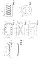
- Figures 1 and 2 show a sectional view of a tray 1 according to the present invention, wherein figure 1 shows the tray 1 in a disassembled state, and wherein figure 2 shows the tray 1 in an assembled state.
- the tray 1 comprises two elements 2, 3.
- One of the elements 2, 3, which will hereinafter be referred to as inlay element 2, is shaped as a flat plate
- another of the elements 2, 3, which will hereinafter be referred to as basic frame 3 is shaped as a shallow cup, wherein its interior space 4 is suitable for receiving and accommodating the inlay element 2.
- Both the inlay element 2 and the basic frame 3 are shown in a normal orientation and mutual position in figures 1 and 2 , i.e. a substantially horizontal orientation, wherein the bottom 5 of the cup shape of the basic frame 3 is at the bottom, and a mutual position in which the inlay element 2 is above the bottom 5 as mentioned.
- a surface 6 of the inlay element 2 which is at the top is intended to be used for supporting items (not shown in figures 1 and 2 ) to be displaced by means of the tray 1 and constitutes thereby a supporting surface 7 of the tray 1.
- indications of orientations and positions will be given with the normal orientation as a basis.
- the basic frame 3 is shaped as a shallow cup, as has already been noted.
- the basic frame 3 comprises a rim 8 which has a standing portion 9.
- This rim portion 9 may serve for preventing items placed on the tray 1 from slipping off.
- the rim 8 has a portion 10 extending outwardly with respect to the standing portion 9. This rim portion 10 is suitable to be taken hold of by a user of the tray 1.
- a tray 1 has at least two elements 2, 3 which are detachably arranged with respect to each other, wherein at least a substantial portion of the supporting surface 7 of the tray 1 is defined by at least one 2 of the elements 2, 3, and wherein at least one other 3 of the elements 2, 3 serves to support the at least one surface defining element 2.
- the assembly of the inlay element 2 and the basic frame 3 as shown in figures 1 and 2 is only one example of the various possibilities existing within the scope of the present invention.
- the basic frame 3 does not necessarily need to be shaped like a shallow cup, but may also be shaped like a flat plate.
- the present invention proposes a detachable connection between the elements 2, 3 of the tray 1.
- Such connection may be realized in any suitable available manner, wherein it is preferred when both the processes of assembling and disassembling the tray 1 may be performed in a simple manner with a minimum of necessary actions.
- the elements 2, 3 may be provided with means for realizing a snap connection when they are placed on top of each other and lightly pressed against each other. It is most advantageous if such means are also adapted to disconnect as soon as a certain minimum force for pulling the elements 2, 3 apart is exerted.
- connection means are designed in such a way that all it takes to assemble the tray 1 is properly positioning the elements 2, 3 with respect to each other and lightly pressing the elements 2, 3 against each other, and that all it takes to disassemble the tray 1 is pulling the elements 2, 3 apart by exerting a force that is low enough to be provided by hand, and by any person.
- the connection means may comprise a kind of guiding rim, wherein the inlay element 2 is connected to the basic frame 3 by sliding the inlay element 2 with respect to the basic frame 3 and letting the guiding rim of the basic frame 3 engage edges of the inlay element 2 in the process.
- Figures 3-8 show various alternative embodiment of the basic frame 3, in order to illustrate a number of further possibilities existing within the scope of the present invention.
- Figure 3 serves to illustrate that the basic frame 3 may have a central hole 11, whereby weight is saved. Furthermore, it is shown that the basic frame 3 may have several items 12 which are arranged near its periphery and around the hole 11, and which are intended to be used for establishing a connection to the inlay element 2. Another possible feature of the basic frame 3 which is shown in figure 3 is a provision of handles 13.
- Figures 4 and 5 serve to illustrate that in case the basic frame 3 has a central hole 11 as shown in figure 3 , the basic frame 3 may also have strips 14 extending in the space of the hole 11. Such strips 14 may be arranged for the purpose of providing the basic frame 3 with the necessary strength, and may play a role in supporting the inlay element 2 in the assembled state of the tray 1.
- the number and positioning of the strips 14 may be chosen freely. It is preferred if the strips 14 are positioned such that they may serve for as a support for fingertips of a person who puts his/her hands around the edge of the basic frame 3, and who may otherwise unintentionally press the inlay element 2 away from the basic frame 3 if the connection between the elements 2, 3 is detachable in that way.
- Figure 6 serves to illustrate that in case the basic frame 3 has weight-reducing features, this does not necessarily need to involve the provision of one or more holes 11.
- at least one area of the basic frame 3, for example, a central area may have a honeycomb structure 15.
- Figure 7 serves to illustrate that the periphery of the basic frame 3 may have any suitable shape.
- the periphery has a rectangular shape.
- This figure 7 illustrates the alternative possibility of a circular shape.
- Figure 8 serves to illustrate that the basic frame 3 may be provided with any suitable pattern of holes 11 and strips 14, which may even be such that the basic frame 3 is also suitable to be used separately as a tray which is adapted to receive smaller trays of a predetermined shape, wherein such smaller trays are intended to be positioned in the holes 11, and may have a more or less conical or stepped shape for allowing the trays to enter the holes 11 on the one hand, but to prevent the trays from completely falling through the holes 11 on the other hand.
- the basic frame 3 may be provided with one or more holes 16 and/or recesses 17 for receiving and accommodating any desired item(s), wherein a circumference of the holes 16 and/or recesses 17 may have any suitable shape.
- Figure 9 shows an example in which the basic frame 3 has three circular holes 16.
- Figures 10 and 11 serve to illustrate how a cup 18 may be positioned inside one of the holes 16.
- the cup 18 has a conical shape, wherein a diameter of the cup 18 at a bottom side of the cup 18 is smaller than a diameter of the hole 16, whereas a diameter of the cup 18 at a top side of the cup 18 is larger than the diameter of the hole 16. Due to this fact, it is possible for the cup 18 to be retained inside the hole 16 in a way as shown in figure 11 .
- Figure 12 shows an embodiment.of the tray 1 in which the basic frame 3 has a circular hole 16 for receiving and accommodating a cup 18 or the like, and an elongate recess 17 for receiving and accommodating cutlery 19 or the like. It is noted once again that numerous possibilities exist within the scope of the present invention as far as the provision of holes 16 and/or recesses 17 for holding items is concerned.
- Figure 13 serves to illustrate another possibility, namely a hole 16 which is open to the periphery of the basic frame 3, which is particularly suitable for receiving an accommodating a wineglass to be inserted from the side due to its specific shape.
- Figure 14 serves to illustrate the fact that it is also possible for the inlay element 2 to have holes 16 and/or recesses 17, and that the circumference of such holes 16 and/or recesses 17 may have any suitable shape.
- the inlay element 2 comprises three holes 16, wherein the circumference of each of the holes 16 has a different shape.
- Figures 15 and 16 illustrate two alternatives of the design of the basic frame 3 to be used in the tray 1 as shown in figure 14 .
- the basic frame 3 may have a rim 8 which is at a higher level than the rest of the basic frame 3 in a normal orientation, so that when items 18 are placed in the holes 16, it is achieved that when the tray 1 having the items 18 is placed on a surface such as a table top, bottoms of the items 18 touch the surface first, after which the tray 1 moves to touch the surface as well, wherein the items 18 are released from the tray 1.
- the basic frame 3 may have a rim 8 which is at a lower level than.the rest of the basic frame 3 in a normal orientation, wherein dimensions may be chosen such that when items 18 are placed in the holes 16, it is achieved that when the tray 1 having the items 18 is placed on a surface such as a table top, the items 18 are not allowed to touch the surface and remain hanging in the tray 1.
- Figures 17 and 18 illustrate an advantageous option existing within the scope of the present invention.
- the inlay element 2 is shaped as a shallow cup, wherein a lid 20 is hingeably arranged on the inlay element 2.
- the lid 20 is movable between an opened position for providing free access to the surface 6 and an interior space 21 of the inlay element 2, and a closed position for sealing this interior space 21.
- a closed container may be obtained, which is removable from the basic frame 3.
- the option of having a space 21 in the tray 1 which is sealable is advantageous in many feasible applications of the tray 1, as is the option of having a removably arranged container.
- the first option may also be realized in an embodiment of the tray 1 in which a lid 20 is arranged on the basic frame 3.
- the lid 20 does not necessarily need to be hingeably arranged on the tray 1.
- a slidable arrangement is also possible. All in all, the lid 20 may come in every suitable size, shape and material, and may be embossed and/or provided with any type of print as desired.
- a number of lids may be provided, which is handy in case it is desired to cover several compartments which may be present in the inlay element 2, one at a time.
- the tray 1 according to the present invention which has at least two elements 2, 3 which are detachably arranged with respect to each other, is suitable to be used in various applications.
- the tray 1 is prepared for use by taking the basic frame 3 and putting the inlay element 2 in place with respect to the basic frame 3, while establishing a temporary connection. After use, the inlay element 2 may be removed, and may be cleaned if so desired, or thrown away. It will be understood that the basic frame 3 may be cleaned at any time as well, but it may be expected that there is not so much need for cleaning in view of the fact that it is the inlay element 2 which is most likely to get dirty under the influence of spilled drinks etc. Furthermore, it is preferred if the basic frame 3 is a durable element, but this is not essential.
- the basic frame 3 may be part of a collection of basic frames 3 and inlay elements 2 for forming trays 1, wherein the inlay elements 2 may be of various types. This fact provides for optimal flexibility in applying the trays 1 for various specific functions. Besides an enhanced flexibility as far as its application is concerned, the tray 1 according to the present invention has many more advantages, including the advantages which have already been mentioned in the foregoing.
- the tray 1 according to the present invention may comprise more than one inlay element 2.
- the inlay elements 2 may have different size, shape, color, etc.
- a lid 20 for covering at least a portion of a supporting surface 7 of a tray 1 is not limited to trays 1 having at least two elements 2, 3 as described here. It is also possible to use a lid 20 in combination with a conventional single-piece tray or any other known type of tray. In that way, a device which is suitable to be used as both a tray and a container may be realized. In this respect, it is also possible to have a plurality of individual lids if so desired.
- the tray 1 which has a supporting surface 7 for supporting items such as food items and/or drinks has been disclosed.
- the tray 1 comprises two elements 2, 3 which are detachably arranged with respect to each other, wherein one 2 of the elements 2, 3 has at least a substantial portion of the supporting surface 7.
- this one 2 of the elements 2, 3 is shaped as a plate, wherein the other 3 of the elements 2, 3 is adapted to support the plate.
- the detachable connection may be a snap connection, such that assembling the tray 1 only requires pressing together the elements 2, 3, and disassembling the tray 1 only requires pulling the elements 2, 3 apart. In such a case, it is very easy for a user to deal with the tray 1.
- the element 2 having at least a substantial portion of the supporting surface 7 is interchangeable, which offers many interesting possibilities.
- both elements 2, 3 of the tray 1 may be light-weight, so that the tray 1 is suitable to be used on air planes, for example.
Landscapes
- Details Of Rigid Or Semi-Rigid Containers (AREA)
Priority Applications (2)
| Application Number | Priority Date | Filing Date | Title |
|---|---|---|---|
| EP08017187A EP2168462A1 (de) | 2008-09-30 | 2008-09-30 | Ablagekasten, der einen Grundrahmen und mindestens ein Einlageelement umfasst |
| PCT/NL2009/000189 WO2010039027A1 (en) | 2008-09-30 | 2009-09-30 | Tray comprising a basic frame and at least one inlay element |
Applications Claiming Priority (1)
| Application Number | Priority Date | Filing Date | Title |
|---|---|---|---|
| EP08017187A EP2168462A1 (de) | 2008-09-30 | 2008-09-30 | Ablagekasten, der einen Grundrahmen und mindestens ein Einlageelement umfasst |
Publications (1)
| Publication Number | Publication Date |
|---|---|
| EP2168462A1 true EP2168462A1 (de) | 2010-03-31 |
Family
ID=40278932
Family Applications (1)
| Application Number | Title | Priority Date | Filing Date |
|---|---|---|---|
| EP08017187A Withdrawn EP2168462A1 (de) | 2008-09-30 | 2008-09-30 | Ablagekasten, der einen Grundrahmen und mindestens ein Einlageelement umfasst |
Country Status (2)
| Country | Link |
|---|---|
| EP (1) | EP2168462A1 (de) |
| WO (1) | WO2010039027A1 (de) |
Cited By (1)
| Publication number | Priority date | Publication date | Assignee | Title |
|---|---|---|---|---|
| CN104825030A (zh) * | 2015-05-25 | 2015-08-12 | 遂宁市长丰机械科技有限公司 | 方便饭盒架 |
Citations (8)
| Publication number | Priority date | Publication date | Assignee | Title |
|---|---|---|---|---|
| US3494502A (en) * | 1968-03-20 | 1970-02-10 | Phillips Petroleum Co | Tray |
| GB1268063A (en) * | 1968-07-29 | 1972-03-22 | Plastics Inc | Disposable trays |
| DE8707605U1 (de) * | 1987-05-27 | 1987-07-16 | Eberlein, Herbert, Dipl.-Ing., 8871 Bubesheim | Stapelbarer Behälter zur Aufnahme einer aus mehreren Speisen bestehenden Mahlzeit |
| DE19702057A1 (de) * | 1997-01-22 | 1998-07-23 | Nicole Sanner | Modulares Geschirrsystem |
| US5950856A (en) * | 1997-04-15 | 1999-09-14 | Cinque; Richard | Plate and cup holder |
| WO2000010436A1 (de) * | 1998-08-19 | 2000-03-02 | Christophe Walch | Serviertablett |
| US20070277711A1 (en) * | 2006-05-30 | 2007-12-06 | Margaret Jean Grant | Impact collapsible non-rigid lap tray with four surrounding high sides |
| WO2008074009A2 (en) * | 2006-12-13 | 2008-06-19 | Meng Koay Lim | Cup holder for a plate |
Family Cites Families (1)
| Publication number | Priority date | Publication date | Assignee | Title |
|---|---|---|---|---|
| US3113710A (en) * | 1961-12-20 | 1963-12-10 | American Can Co | Disposable serving tray |
-
2008
- 2008-09-30 EP EP08017187A patent/EP2168462A1/de not_active Withdrawn
-
2009
- 2009-09-30 WO PCT/NL2009/000189 patent/WO2010039027A1/en not_active Ceased
Patent Citations (8)
| Publication number | Priority date | Publication date | Assignee | Title |
|---|---|---|---|---|
| US3494502A (en) * | 1968-03-20 | 1970-02-10 | Phillips Petroleum Co | Tray |
| GB1268063A (en) * | 1968-07-29 | 1972-03-22 | Plastics Inc | Disposable trays |
| DE8707605U1 (de) * | 1987-05-27 | 1987-07-16 | Eberlein, Herbert, Dipl.-Ing., 8871 Bubesheim | Stapelbarer Behälter zur Aufnahme einer aus mehreren Speisen bestehenden Mahlzeit |
| DE19702057A1 (de) * | 1997-01-22 | 1998-07-23 | Nicole Sanner | Modulares Geschirrsystem |
| US5950856A (en) * | 1997-04-15 | 1999-09-14 | Cinque; Richard | Plate and cup holder |
| WO2000010436A1 (de) * | 1998-08-19 | 2000-03-02 | Christophe Walch | Serviertablett |
| US20070277711A1 (en) * | 2006-05-30 | 2007-12-06 | Margaret Jean Grant | Impact collapsible non-rigid lap tray with four surrounding high sides |
| WO2008074009A2 (en) * | 2006-12-13 | 2008-06-19 | Meng Koay Lim | Cup holder for a plate |
Cited By (1)
| Publication number | Priority date | Publication date | Assignee | Title |
|---|---|---|---|---|
| CN104825030A (zh) * | 2015-05-25 | 2015-08-12 | 遂宁市长丰机械科技有限公司 | 方便饭盒架 |
Also Published As
| Publication number | Publication date |
|---|---|
| WO2010039027A1 (en) | 2010-04-08 |
Similar Documents
| Publication | Publication Date | Title |
|---|---|---|
| CA2713908C (en) | Burger press | |
| USD550077S1 (en) | Game pack | |
| USD644064S1 (en) | Reconfigurable container | |
| USD570650S1 (en) | Wave pattern food container | |
| US4659099A (en) | Food and item tray for a walker and a wheelchair | |
| USD572087S1 (en) | Food storage container | |
| USD637445S1 (en) | Tea kettle | |
| USD541648S1 (en) | Pet food container and lid | |
| USD914518S1 (en) | Plastic food container | |
| US20120205383A1 (en) | Serving tray assembly with disposal opening | |
| USD528412S1 (en) | Container with lid | |
| USD595572S1 (en) | Shallow lid for food container | |
| USD535202S1 (en) | Ergonomic electronic thermometer | |
| USD575023S1 (en) | Cart | |
| USD874945S1 (en) | Plastic food container | |
| EP2590804B1 (de) | Versiegelungsmaschine | |
| WO2010039027A1 (en) | Tray comprising a basic frame and at least one inlay element | |
| US2820423A (en) | Food molding devices | |
| USD513688S1 (en) | Square vacuum container | |
| US20070131697A1 (en) | Plate with utensil pocket | |
| USD586520S1 (en) | Waste container | |
| NL2004805C2 (nl) | Voedselhouder. | |
| WO1995029619A1 (en) | Food delivery container | |
| KR200440381Y1 (ko) | 도마 | |
| JP3190750U (ja) | 積上げ可能式弁当箱 |
Legal Events
| Date | Code | Title | Description |
|---|---|---|---|
| PUAI | Public reference made under article 153(3) epc to a published international application that has entered the european phase |
Free format text: ORIGINAL CODE: 0009012 |
|
| AK | Designated contracting states |
Kind code of ref document: A1 Designated state(s): AT BE BG CH CY CZ DE DK EE ES FI FR GB GR HR HU IE IS IT LI LT LU LV MC MT NL NO PL PT RO SE SI SK TR |
|
| AX | Request for extension of the european patent |
Extension state: AL BA MK RS |
|
| AKY | No designation fees paid | ||
| REG | Reference to a national code |
Ref country code: DE Ref legal event code: 8566 |
|
| STAA | Information on the status of an ep patent application or granted ep patent |
Free format text: STATUS: THE APPLICATION IS DEEMED TO BE WITHDRAWN |
|
| 18D | Application deemed to be withdrawn |
Effective date: 20101001 |